 Products Home / Polarization Optics / Polarizers / Polarizing Beamsplitters / High-Power, Broadband, High Extinction Ratio Polarizing Beamsplitters
High-Power, Broadband, High Extinction Ratio Polarizing Beamsplitters

- High Extinction Ratio Up to 100 000:1
- Broadband Operation with Options from 700 to 1300 nm
- High Damage Threshold
- Alternative to Crystalline-Based Polarizers
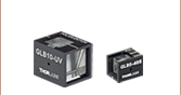
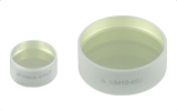
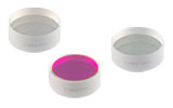
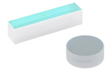
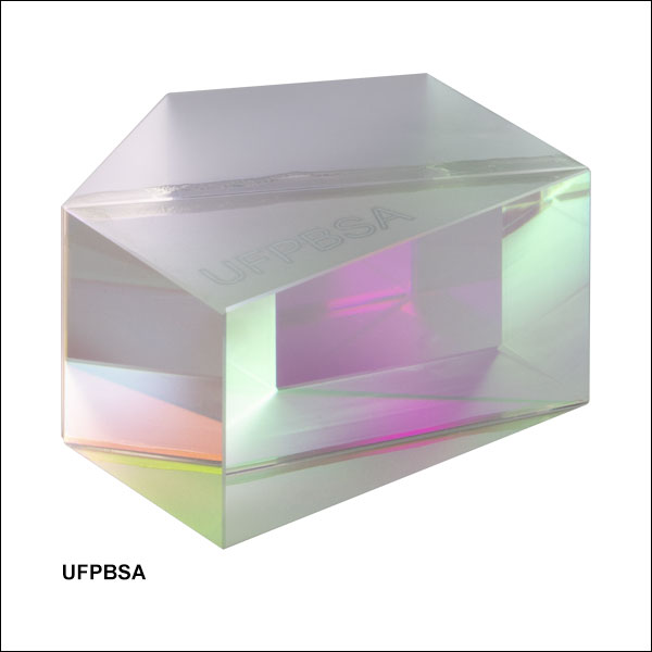
UFPBSA
Low-GDD, High-Power, Broadband
Polarizing Beamsplitter, 700 -1100 nm
Application Idea
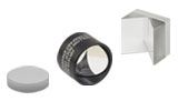
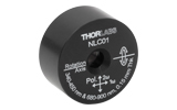
UFPBS103 Hexagonal Beamsplitter Mounted on a KM100PM Platform Mount with a PM3 Clamping Arm
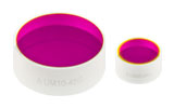
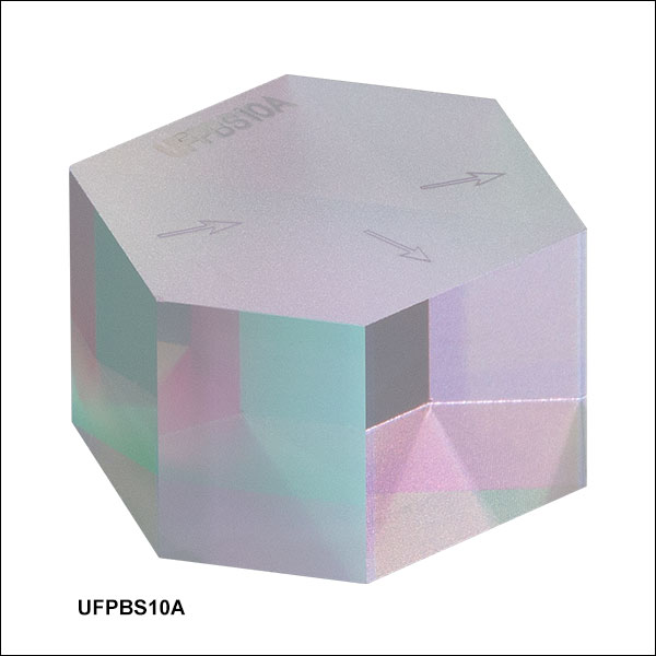
UFPBS10A
High-Power, Broadband
Polarizing Beamsplitter,
780 - 1080 nm
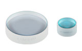
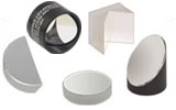
UFPBS053
High-Power, Broadband
Polarizing Beamsplitter,
900 - 1300 nm


Please Wait
| Table 1.1 Key Specifications | |||
|---|---|---|---|
| Item # | UFPBSA | UFPBS10A | UFPBSxx3 |
| Design Wavelength | 700 - 1100 nm | 720 - 1080 nm | 900 - 1300 nm |
| Extinction Ratioa | Tp:Ts > 1000:1 (700 - 1100 nm) Tp:Ts > 5000:1 (750 - 1000 nm) Tp:Ts > 10 000:1 (800 - 900 nm) |
Tp:Ts > 1000:1 (720 - 1080 nm) Tp:Ts > 10 000:1 (730 - 1060 nm) Tp:Ts > 100 000:1 (800 - 900 nm) |
Tp:Ts > 1000:1 (900 - 1300 nm) Tp:Ts > 10 000:1 (900 - 1250 nm) Tp:Ts > 100 000:1 (980 - 1080 nm) |
| Reflected Beam Deviation | 60.0° ± 5 arcmin | 66.3° ± 5 arcmin | 67.5° ± 5 arcmin |
| Group Delay Dispersionb | |GDDp| < 10 fs2 |GDDs| < 25 fs2 |
|GDDp,s| < 40 fs2 | |GDDp,s| < 30 fs2 |

Features
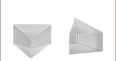
- Pentagonal Design for Unidirectional Operation or Hexagonal Design for Bi-directional Operation
- Broadband Design Wavelength Ranges
- 700 - 1100 nm, 720 - 1080 nm, or 900 - 1300 nm
- High Extinction Ratio
- High Power Handling (See Damage Thresholds Tab)
- Low Group Delay Dispersion
- Epoxy-Free Optical Contact at Beamsplitter Interface Minimizes Absorption and Scattering Losses
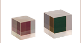
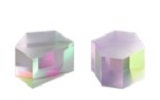
Thorlabs' High-Power Broadband Polarizing Beamsplitters are ideal for both Ti:sapphire and ytterbium (Yb) femtosecond lasers, as well as other broad bandwidth or tunable laser sources. The pentagonal UFPBSA beamsplitter is designed for use over a wavelength range of 700 - 1100 nm, while the hexagonal beamsplitters are designed for use over a wavelength range of 720 - 1080 nm or 900 - 1300 nm. The input/output faces of the beamsplitters are AR-coated, as indicated in Figures 1.2 and 1.3, to minimize reflectance over their respective wavelength ranges. The beamsplitters separate the s- and p-polarization components of the incident laser by reflecting the s-component at the dielectric beamsplitter coating, while allowing the p-component to transmit through.
The UFPBSA pentagonal beamsplitter reflects the s-component at 60.0° while the UFPBS10A and UFPBSxx3 hexagonal beamsplitters reflect the s-component at 66.3° or 67.5°, respectively. The unique geometries have a transmission greater than 98% for the p-component and reflect the s-component with greater than 99.9% (UFPBSA pentagonal beamsplitter), 99% (UFPBS10A hexagonal beamsplitter), or 99.5% (UFPBSxx3 hexagonal beamsplitters) efficiency across their broadband wavelength ranges, yielding an extinction ratio (Tp:Ts) better than 1000:1. The extinction ratios over wavelength bands within the specified total operational ranges can be found in Table 1.1.
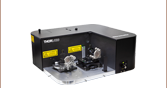
The dielectric beamsplitter coatings are designed to yield low group delay dispersion (GDD). The pentagonal thin-film design has a |GDD| of less than 10 fs2 for the transmitted p-polarization and a |GDD| less than 25 fs2 for the reflected s-polarization, while the hexagonal thin-film designs have a |GDD| less than 40 fs2 (UFPBS10A beamsplitter) or 30 fs2 (UFPBSxx3 beamsplitters) for both the transmitted p-polarization and reflected s-polarization. For details on transmission and GDD, please see the Graphs tab. To characterize the dispersion properties, including the phase, group delay, GDD, third-order dispersion, and fourth-order dispersion, please see our Chromatis™ dispersion measurement system.
The beamsplitter interface uses an epoxy-free, optical contact bond, which minimizes absorption and scattering loss allowing for high damage thresholds (see the Specs tab). Each surface is polished to a high flatness, and this precision polishing of the internal surfaces is what enables them to achieve optical contact. As such, Thorlabs is able to manufacture compact, thermally stable beamsplitters with high transmission and minimal beam displacement.
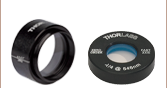
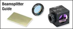
Thorlabs offers a variety of mounting solutions, including both compact platform mounts, as seen in the image on the upper right, and kinematic platform mounts. Please note that, due to the unique geometries of Thorlabs' broadband polarizing beamsplitters, certain compact mounts designed for our beamsplitter cubes will not properly fit these designs. When mounting, care should be taken to keep from applying unnecessary stress on the polarizer, which can reduce the attainable extinction ratio by creating stress-induced birefringence inside the polarizer.
 Click for Details
Figure 1.3 Hexagonal Broadband Polarizing Beamsplitter Diagram
The symmetric hexagonal design allows for use of all 4 entrance/exit ports, like the more common polarizing beamsplitter cubes.
 Click for Details
Figure 1.2 Pentagonal Broadband Polarizing Beamsplitter Diagram
| Specifications | ||||
|---|---|---|---|---|
| Item # | UFBSA | UFPBS10A | UFPBS053 | UFPBS103 |
| Material | Fused Silica | Fused Silica | Fused Silica | |
| Design Wavelength | 700 - 1100 nm | 720 - 1080 nm | 900 - 1300 nm | |
| Extinction Ratioa | Tp:Ts > 1000:1 (700 - 1100 nm) Tp:Ts > 5000:1 (750 - 1000 nm) Tp:Ts > 10 000:1 (800 - 900 nm) |
Tp:Ts > 1000:1 (720 - 1080 nm) Tp:Ts > 10 000:1 (730 - 1060 nm) Tp:Ts > 100 000:1 (800 - 900 nm) |
Tp:Ts > 1000:1 (900 - 1300 nm) Tp:Ts > 10 000:1 (900 - 1250 nm) Tp:Ts > 100 000:1 (980 - 1080 nm) |
|
| Transmission Efficiency | Tp > 98% | Tp > 98% | Tp > 98% | |
| Reflection Efficiency | Rs > 99.9% | Rs > 99% | Rs > 99.5% | |
| Transmitted Beam Deviation | 0° ± 5 arcmin | 0° ± 5 arcmin | 0° ± 5 arcmin | |
| Reflected Beam Deviation | 60° ± 5 arcmin | 66.3° ± 5 arcmin | 67.5° ± 5 arcmin | |
| Group Delay Dispersionb | |GDDp| < 10 fs2 |GDDs| < 25 fs2 |
|GDDp,s| < 40 fs2 | |GDDp,s| < 30 fs2 | |
| Clear Aperture | >80% of 12.7 mm x 12.7 mm | >80% of 10.0 mm x 10.0 mm | >80% of 5.0 mm x 5.0 mm |
>80% of 10.0 mm x 10.0 mm |
| Dimensional Tolerance | ±0.1 mm | ±0.1 mm | ±0.1 mm | |
| AR Coating Reflectance | <0.5% per Surface (700 - 1100 nm) |
<0.5% per Surface (720 - 1080 nm) |
<0.5% per Surface (900 - 1300 nm) | |
| Transmitted Wavefront Errorc | <λ/4 at 633 nm | <λ/4 at 633 nm | <λ/4 at 633 nm | |
| Surface Quality | 20-10 Scratch-Dig | 20-10 Scratch-Dig | 20-10 Scratch-Dig | |
| Damage Threshold | Pulsed: 0.039 J/cm2 (1030 nm, 500 fs,1 kHz, Ø270 µm, 100 000 Pulses); Pulse: 3.2 J/cm2 (1030 nm, 135 ps, 50 kHz, Ø70 µm, 10 000 Pulses); Pulse: 7.4 J/cm2 (1064 nm, 10 ns, 10 Hz, Ø230 µm, 1000 Pulses) |
Pulse: 6.5 J/cm2 (800 nm, 135 ps, 1 kHz, Ø89 µm, 10 000 Pulses) Pulse: 19.0 J/cm2 (1064 nm, 10 ns, 10 Hz, Ø230 µm, 1000 Pulses) |
CW: 200 000 W/cm (51 MW/cm2 ,1070 nm, Ø100 µm); Pulse: 7.8 J/cm2 (1030 nm, 135 ps, 50 kHz, Ø70 µm, 10 000 Pulses) Pulse: 7.4 J/cm2 (1064 nm, 10 ns, 10 Hz, Ø230 µm, 1000 Pulses); |
|
UFPBSA Polarizing Beamsplitter Transmission and Group Delay Dispersion (GDD) Data
Figure 3.1 shows typical transmission for our UFPBSA beamsplitter. Figure 3.2 shows typical measurements for the GDD introduced by the coatings, taken with a Chromatis™ dispersion measurement system.
Click to Enlarge
Click for Raw Data
Figure 3.1 The shaded region represents the design wavelength range over which Tp > 98% and Rs > 99.9%. This transmission data is approximate and not suitable for calculating extinction ratio.
Click to Enlarge
Click for Raw Data
Figure 3.2 This graph represents the GDD introduced by the coatings only, not the bulk material of the beamsplitter, for the reflected s-polarized light and the transmitted p-polarized light. The shaded region represents the design wavelength range. The GDD values fluctuate rapidly outside of the specified wavelength range of 700 - 1100 nm for s-polarized light.
h
UFPBS10A Polarizing Beamsplitter Transmission, Reflectance, Extinction Ratio (ER), and Group Delay Dispersion (GDD) Data
Figure 3.3 shows the net calculated transmission of both s- and p-polarizations through two AR-coated surfaces and the polarizing thin-film coating of the hexagonal beamsplitter. Figure 3.4 shows the reflectance of an AR-coated surface of the beamsplitter.
The extinction ratio (ER), the ratio of transmitted p-polarized light to transmitted s-polarized light (Tp:Ts), of the beamsplitter is shown in Figure 3.5. Figure 3.6 shows the group delay dispersion due to the coating design of the thin-film polarizing interface of the beamsplitter; the GDD contribution from the AR coating is negligible.

Click to Enlarge
Click for Raw Data
Figure 3.3 The shaded region represents the design wavelength range over which Tp > 98% and Rs > 99%. This data is the calculated net transmission through two AR-coated surfaces and the polarizing thin-film coating of the beamsplitter.

Click to Enlarge
Click for Raw Data
Figure 3.4 This graph shows the reflectance of an AR-coated surface of the beamsplitter with the shaded region representing the design wavelength range over which R < 0.5%.
Click to Enlarge
Click for Raw Data
Figure 3.6 This graph represents the GDD introduced by the thin-film polarizing interface only, not the bulk material of the beamsplitter, for the reflected s-polarized light and the transmitted p-polarized light. The shaded region represents the design wavelength range. The GDD values fluctuate rapidly outside of the specified wavelength range of 720 - 1080 nm for s-polarized light.
Click to Enlarge
Click for Raw Data
Figure 3.5 Here the extinction ratio is assessed by two methods: The blue curve (Theoretical ER) is the calculated ratio of the linearly polarized transmission curves Tp and Ts. The black squares are measured data points where the incident beam polarization is prepared with a reference calcite polarizer that has an ER of 106:1.
h
UFPBSxx3 Polarizing Beamsplitter Transmission, Reflectance, Extinction Ratio (ER), and Group Delay Dispersion (GDD) Data
Figure 3.7 shows the net calculated transmission of both s- and p-polarizations through two AR-coated surfaces and the polarizing thin-film coating of the hexagonal beamsplitter. Figure 3.8 shows the reflectance of an AR-coated surface of the beamsplitter.
The extinction ratio (ER), the ratio of transmitted p-polarized light to transmitted s-polarized light (Tp:Ts), of the beamsplitter is shown in Figure 3.9. Figure 3.10 shows the group delay dispersion due to the coating design of the thin-film polarizing interface of the beamsplitter; the GDD contribution from the AR coating is negligible.

Click to Enlarge
Click for Raw Data
Figure 3.7 The shaded region represents the design wavelength range over which Tp > 98% and Rs > 99.5%. This data is the calculated net transmission through two AR-coated surfaces and the polarizing thin-film coating of the beamsplitter.
Click to Enlarge
Click for Raw Data
Figure 3.8 This graph shows the reflectance of an AR-coated surface of the beamsplitter with the shaded region representing the design wavelength range over which R < 0.5%.
Click to Enlarge
Click for Raw Data
Figure 3.10 This graph represents the GDD introduced by the thin-film polarizing interface only, not the bulk material of the beamsplitter, for the reflected s-polarized light and the transmitted p-polarized light. The shaded region represents the design wavelength range. The GDD values fluctuate rapidly outside of the specified wavelength range of 900 - 1300 nm for s-polarized light.

Click to Enlarge
Click for Raw Data
Figure 3.9 Here the extinction ratio is assessed by two methods: The blue curve (Theoretical ER) is the calculated ratio of the linearly polarized transmission curves Tp and Ts. The black squares are measured data points where the incident beam polarization is prepared with a reference calcite polarizer that has an ER of 106:1.
| Table 4.1 Damage Threshold Specifications | |||
|---|---|---|---|
| Item # | Damage Threshold | ||
| UFPBSA | Pulseda | 0.039 J/cm2 (1030 nm, 500 fs, 1 kHz, Ø270 µm, 100 000 Pulses) | |
| Pulsed | 3.2 J/cm2 (1030 nm, 135 ps, 50 kHz, Ø70 µm, 10 000 Pulses) | ||
| Pulsed | 7.4 J/cm2 (1064 nm, 10 ns, 10 Hz, Ø230 µm, 1000 Pulses) | ||
| UFPBS10A | Pulsed | 6.5 J/cm2 (800 nm, 135 ps, 1 kHz, Ø89 µm, 10 000 Pulses) | |
| Pulsed | 19.0 J/cm2 (1064 nm, 10 ns, 10 Hz, Ø230 µm, 1000 Pulses) | ||
| UFPBSxx3 | CWb | 200 000 W/cm, (51 MW/cm2, 1070 nm, Ø100 µm) | |
| Pulsed | 7.8 J/cm2 (1030 nm, 135 ps, 50 kHz, Ø70 µm, 10 000 Pulses) | ||
| Pulsed | 7.4 J/cm2 (1064 nm, 10 ns, 10 Hz, Ø230 µm, 1000 Pulses) | ||
Damage Threshold Data for Thorlabs' High Extinction Ratio, High-Power, Broadband Polarizing Beamsplitters
The specifications in Table 4.1 are measured data for Thorlabs' high-power, high-extinction ratio broadband polarizing beamsplitters. Damage threshold specifications are limited by the beamsplitter coating and are constant for a given coating type, regardless of the size of the optic.
Laser Induced Damage Threshold Tutorial
The following is a general overview of how laser induced damage thresholds are measured and how the values may be utilized in determining the appropriateness of an optic for a given application. When choosing optics, it is important to understand the Laser Induced Damage Threshold (LIDT) of the optics being used. The LIDT for an optic greatly depends on the type of laser you are using. Continuous wave (CW) lasers typically cause damage from thermal effects (absorption either in the coating or in the substrate). Pulsed lasers, on the other hand, often strip electrons from the lattice structure of an optic before causing thermal damage. Note that the guideline presented here assumes room temperature operation and optics in new condition (i.e., within scratch-dig spec, surface free of contamination, etc.). Because dust or other particles on the surface of an optic can cause damage at lower thresholds, we recommend keeping surfaces clean and free of debris. For more information on cleaning optics, please see our Optics Cleaning tutorial.
Testing Method
Thorlabs' LIDT testing is done in compliance with ISO/DIS 11254 and ISO 21254 specifications.
First, a low-power/energy beam is directed to the optic under test. The optic is exposed in 10 locations to this laser beam for 30 seconds (CW) or for a number of pulses (pulse repetition frequency specified). After exposure, the optic is examined by a microscope (~100X magnification) for any visible damage. The number of locations that are damaged at a particular power/energy level is recorded. Next, the power/energy is either increased or decreased and the optic is exposed at 10 new locations. This process is repeated until damage is observed. The damage threshold is then assigned to be the highest power/energy that the optic can withstand without causing damage. A histogram such as that below represents the testing of one BB1-E02 mirror.

The photograph above is a protected aluminum-coated mirror after LIDT testing. In this particular test, it handled 0.43 J/cm2 (1064 nm, 10 ns pulse, 10 Hz, Ø1.000 mm) before damage.

| Example Test Data | |||
|---|---|---|---|
| Fluence | # of Tested Locations | Locations with Damage | Locations Without Damage |
| 1.50 J/cm2 | 10 | 0 | 10 |
| 1.75 J/cm2 | 10 | 0 | 10 |
| 2.00 J/cm2 | 10 | 0 | 10 |
| 2.25 J/cm2 | 10 | 1 | 9 |
| 3.00 J/cm2 | 10 | 1 | 9 |
| 5.00 J/cm2 | 10 | 9 | 1 |
According to the test, the damage threshold of the mirror was 2.00 J/cm2 (532 nm, 10 ns pulse, 10 Hz, Ø0.803 mm). Please keep in mind that these tests are performed on clean optics, as dirt and contamination can significantly lower the damage threshold of a component. While the test results are only representative of one coating run, Thorlabs specifies damage threshold values that account for coating variances.
Continuous Wave and Long-Pulse Lasers
When an optic is damaged by a continuous wave (CW) laser, it is usually due to the melting of the surface as a result of absorbing the laser's energy or damage to the optical coating (antireflection) [1]. Pulsed lasers with pulse lengths longer than 1 µs can be treated as CW lasers for LIDT discussions.
When pulse lengths are between 1 ns and 1 µs, laser-induced damage can occur either because of absorption or a dielectric breakdown (therefore, a user must check both CW and pulsed LIDT). Absorption is either due to an intrinsic property of the optic or due to surface irregularities; thus LIDT values are only valid for optics meeting or exceeding the surface quality specifications given by a manufacturer. While many optics can handle high power CW lasers, cemented (e.g., achromatic doublets) or highly absorptive (e.g., ND filters) optics tend to have lower CW damage thresholds. These lower thresholds are due to absorption or scattering in the cement or metal coating.

LIDT in linear power density vs. pulse length and spot size. For long pulses to CW, linear power density becomes a constant with spot size. This graph was obtained from [1].

Pulsed lasers with high pulse repetition frequencies (PRF) may behave similarly to CW beams. Unfortunately, this is highly dependent on factors such as absorption and thermal diffusivity, so there is no reliable method for determining when a high PRF laser will damage an optic due to thermal effects. For beams with a high PRF both the average and peak powers must be compared to the equivalent CW power. Additionally, for highly transparent materials, there is little to no drop in the LIDT with increasing PRF.
In order to use the specified CW damage threshold of an optic, it is necessary to know the following:
- Wavelength of your laser
- Beam diameter of your beam (1/e2)
- Approximate intensity profile of your beam (e.g., Gaussian)
- Linear power density of your beam (total power divided by 1/e2 beam diameter)
Thorlabs expresses LIDT for CW lasers as a linear power density measured in W/cm. In this regime, the LIDT given as a linear power density can be applied to any beam diameter; one does not need to compute an adjusted LIDT to adjust for changes in spot size, as demonstrated by the graph to the right. Average linear power density can be calculated using the equation below.

The calculation above assumes a uniform beam intensity profile. You must now consider hotspots in the beam or other non-uniform intensity profiles and roughly calculate a maximum power density. For reference, a Gaussian beam typically has a maximum power density that is twice that of the uniform beam (see lower right).
Now compare the maximum power density to that which is specified as the LIDT for the optic. If the optic was tested at a wavelength other than your operating wavelength, the damage threshold must be scaled appropriately. A good rule of thumb is that the damage threshold has a linear relationship with wavelength such that as you move to shorter wavelengths, the damage threshold decreases (i.e., a LIDT of 10 W/cm at 1310 nm scales to 5 W/cm at 655 nm):

While this rule of thumb provides a general trend, it is not a quantitative analysis of LIDT vs wavelength. In CW applications, for instance, damage scales more strongly with absorption in the coating and substrate, which does not necessarily scale well with wavelength. While the above procedure provides a good rule of thumb for LIDT values, please contact Tech Support if your wavelength is different from the specified LIDT wavelength. If your power density is less than the adjusted LIDT of the optic, then the optic should work for your application.
Please note that we have a buffer built in between the specified damage thresholds online and the tests which we have done, which accommodates variation between batches. Upon request, we can provide individual test information and a testing certificate. The damage analysis will be carried out on a similar optic (customer's optic will not be damaged). Testing may result in additional costs or lead times. Contact Tech Support for more information.
Pulsed Lasers
As previously stated, pulsed lasers typically induce a different type of damage to the optic than CW lasers. Pulsed lasers often do not heat the optic enough to damage it; instead, pulsed lasers produce strong electric fields capable of inducing dielectric breakdown in the material. Unfortunately, it can be very difficult to compare the LIDT specification of an optic to your laser. There are multiple regimes in which a pulsed laser can damage an optic and this is based on the laser's pulse length. The highlighted columns in the table below outline the relevant pulse lengths for our specified LIDT values.
Pulses shorter than 10-9 s cannot be compared to our specified LIDT values with much reliability. In this ultra-short-pulse regime various mechanics, such as multiphoton-avalanche ionization, take over as the predominate damage mechanism [2]. In contrast, pulses between 10-7 s and 10-4 s may cause damage to an optic either because of dielectric breakdown or thermal effects. This means that both CW and pulsed damage thresholds must be compared to the laser beam to determine whether the optic is suitable for your application.
| Pulse Duration | t < 10-9 s | 10-9 < t < 10-7 s | 10-7 < t < 10-4 s | t > 10-4 s |
|---|---|---|---|---|
| Damage Mechanism | Avalanche Ionization | Dielectric Breakdown | Dielectric Breakdown or Thermal | Thermal |
| Relevant Damage Specification | No Comparison (See Above) | Pulsed | Pulsed and CW | CW |
When comparing an LIDT specified for a pulsed laser to your laser, it is essential to know the following:

LIDT in energy density vs. pulse length and spot size. For short pulses, energy density becomes a constant with spot size. This graph was obtained from [1].
- Wavelength of your laser
- Energy density of your beam (total energy divided by 1/e2 area)
- Pulse length of your laser
- Pulse repetition frequency (prf) of your laser
- Beam diameter of your laser (1/e2 )
- Approximate intensity profile of your beam (e.g., Gaussian)
The energy density of your beam should be calculated in terms of J/cm2. The graph to the right shows why expressing the LIDT as an energy density provides the best metric for short pulse sources. In this regime, the LIDT given as an energy density can be applied to any beam diameter; one does not need to compute an adjusted LIDT to adjust for changes in spot size. This calculation assumes a uniform beam intensity profile. You must now adjust this energy density to account for hotspots or other nonuniform intensity profiles and roughly calculate a maximum energy density. For reference a Gaussian beam typically has a maximum energy density that is twice that of the 1/e2 beam.
Now compare the maximum energy density to that which is specified as the LIDT for the optic. If the optic was tested at a wavelength other than your operating wavelength, the damage threshold must be scaled appropriately [3]. A good rule of thumb is that the damage threshold has an inverse square root relationship with wavelength such that as you move to shorter wavelengths, the damage threshold decreases (i.e., a LIDT of 1 J/cm2 at 1064 nm scales to 0.7 J/cm2 at 532 nm):

You now have a wavelength-adjusted energy density, which you will use in the following step.
Beam diameter is also important to know when comparing damage thresholds. While the LIDT, when expressed in units of J/cm², scales independently of spot size; large beam sizes are more likely to illuminate a larger number of defects which can lead to greater variances in the LIDT [4]. For data presented here, a <1 mm beam size was used to measure the LIDT. For beams sizes greater than 5 mm, the LIDT (J/cm2) will not scale independently of beam diameter due to the larger size beam exposing more defects.
The pulse length must now be compensated for. The longer the pulse duration, the more energy the optic can handle. For pulse widths between 1 - 100 ns, an approximation is as follows:

Use this formula to calculate the Adjusted LIDT for an optic based on your pulse length. If your maximum energy density is less than this adjusted LIDT maximum energy density, then the optic should be suitable for your application. Keep in mind that this calculation is only used for pulses between 10-9 s and 10-7 s. For pulses between 10-7 s and 10-4 s, the CW LIDT must also be checked before deeming the optic appropriate for your application.
Please note that we have a buffer built in between the specified damage thresholds online and the tests which we have done, which accommodates variation between batches. Upon request, we can provide individual test information and a testing certificate. Contact Tech Support for more information.
[1] R. M. Wood, Optics and Laser Tech. 29, 517 (1998).
[2] Roger M. Wood, Laser-Induced Damage of Optical Materials (Institute of Physics Publishing, Philadelphia, PA, 2003).
[3] C. W. Carr et al., Phys. Rev. Lett. 91, 127402 (2003).
[4] N. Bloembergen, Appl. Opt. 12, 661 (1973).

In order to illustrate the process of determining whether a given laser system will damage an optic, a number of example calculations of laser induced damage threshold are given below. For assistance with performing similar calculations, we provide a spreadsheet calculator that can be downloaded by clicking the LIDT Calculator button. To use the calculator, enter the specified LIDT value of the optic under consideration and the relevant parameters of your laser system in the green boxes. The spreadsheet will then calculate a linear power density for CW and pulsed systems, as well as an energy density value for pulsed systems. These values are used to calculate adjusted, scaled LIDT values for the optics based on accepted scaling laws. This calculator assumes a Gaussian beam profile, so a correction factor must be introduced for other beam shapes (uniform, etc.). The LIDT scaling laws are determined from empirical relationships; their accuracy is not guaranteed. Remember that absorption by optics or coatings can significantly reduce LIDT in some spectral regions. These LIDT values are not valid for ultrashort pulses less than one nanosecond in duration.
Figure 71A A Gaussian beam profile has about twice the maximum intensity of a uniform beam profile.
CW Laser Example
Suppose that a CW laser system at 1319 nm produces a 0.5 W Gaussian beam that has a 1/e2 diameter of 10 mm. A naive calculation of the average linear power density of this beam would yield a value of 0.5 W/cm, given by the total power divided by the beam diameter:
However, the maximum power density of a Gaussian beam is about twice the maximum power density of a uniform beam, as shown in Figure 71A. Therefore, a more accurate determination of the maximum linear power density of the system is 1 W/cm.
An AC127-030-C achromatic doublet lens has a specified CW LIDT of 350 W/cm, as tested at 1550 nm. CW damage threshold values typically scale directly with the wavelength of the laser source, so this yields an adjusted LIDT value:
The adjusted LIDT value of 350 W/cm x (1319 nm / 1550 nm) = 298 W/cm is significantly higher than the calculated maximum linear power density of the laser system, so it would be safe to use this doublet lens for this application.
Pulsed Nanosecond Laser Example: Scaling for Different Pulse Durations
Suppose that a pulsed Nd:YAG laser system is frequency tripled to produce a 10 Hz output, consisting of 2 ns output pulses at 355 nm, each with 1 J of energy, in a Gaussian beam with a 1.9 cm beam diameter (1/e2). The average energy density of each pulse is found by dividing the pulse energy by the beam area:

As described above, the maximum energy density of a Gaussian beam is about twice the average energy density. So, the maximum energy density of this beam is ~0.7 J/cm2.
The energy density of the beam can be compared to the LIDT values of 1 J/cm2 and 3.5 J/cm2 for a BB1-E01 broadband dielectric mirror and an NB1-K08 Nd:YAG laser line mirror, respectively. Both of these LIDT values, while measured at 355 nm, were determined with a 10 ns pulsed laser at 10 Hz. Therefore, an adjustment must be applied for the shorter pulse duration of the system under consideration. As described on the previous tab, LIDT values in the nanosecond pulse regime scale with the square root of the laser pulse duration:
This adjustment factor results in LIDT values of 0.45 J/cm2 for the BB1-E01 broadband mirror and 1.6 J/cm2 for the Nd:YAG laser line mirror, which are to be compared with the 0.7 J/cm2 maximum energy density of the beam. While the broadband mirror would likely be damaged by the laser, the more specialized laser line mirror is appropriate for use with this system.
Pulsed Nanosecond Laser Example: Scaling for Different Wavelengths
Suppose that a pulsed laser system emits 10 ns pulses at 2.5 Hz, each with 100 mJ of energy at 1064 nm in a 16 mm diameter beam (1/e2) that must be attenuated with a neutral density filter. For a Gaussian output, these specifications result in a maximum energy density of 0.1 J/cm2. The damage threshold of an NDUV10A Ø25 mm, OD 1.0, reflective neutral density filter is 0.05 J/cm2 for 10 ns pulses at 355 nm, while the damage threshold of the similar NE10A absorptive filter is 10 J/cm2 for 10 ns pulses at 532 nm. As described on the previous tab, the LIDT value of an optic scales with the square root of the wavelength in the nanosecond pulse regime:
This scaling gives adjusted LIDT values of 0.08 J/cm2 for the reflective filter and 14 J/cm2 for the absorptive filter. In this case, the absorptive filter is the best choice in order to avoid optical damage.
Pulsed Microsecond Laser Example
Consider a laser system that produces 1 µs pulses, each containing 150 µJ of energy at a repetition rate of 50 kHz, resulting in a relatively high duty cycle of 5%. This system falls somewhere between the regimes of CW and pulsed laser induced damage, and could potentially damage an optic by mechanisms associated with either regime. As a result, both CW and pulsed LIDT values must be compared to the properties of the laser system to ensure safe operation.
If this relatively long-pulse laser emits a Gaussian 12.7 mm diameter beam (1/e2) at 980 nm, then the resulting output has a linear power density of 5.9 W/cm and an energy density of 1.2 x 10⁻⁴ J/cm2 per pulse. This can be compared to the LIDT values for a WPQ10E-980 polymer zero-order quarter-wave plate, which are 5 W/cm for CW radiation at 810 nm and 5 J/cm2 for a 10 ns pulse at 810 nm. As before, the CW LIDT of the optic scales linearly with the laser wavelength, resulting in an adjusted CW value of 6 W/cm at 980 nm. On the other hand, the pulsed LIDT scales with the square root of the laser wavelength and the square root of the pulse duration, resulting in an adjusted value of 55 J/cm2 for a 1 µs pulse at 980 nm. The pulsed LIDT of the optic is significantly greater than the energy density of the laser pulse, so individual pulses will not damage the wave plate. However, the large average linear power density of the laser system may cause thermal damage to the optic, much like a high-power CW beam.
Beamsplitter Selection Guide
Thorlabs' portfolio contains many different kinds of beamsplitters, which can split beams by intensity or by polarization. We offer plate and cube beamsplitters, though other form factors exist, including pellicle and birefringent crystal. For an overview of the different types and a comparison of their features and applications, please see our overview. Many of our beamsplitters come in premounted or unmounted variants. In this tab is a complete listing of our beamsplitter offerings. To explore the available types, wavelength ranges, splitting/extinction ratios, transmission, and available sizes for each beamsplitter category, click More [+] in the appropriate row.Plate Beamsplitters
| Non-Polarizing Plate Beamsplitters |
|---|


| Polarizing Plate Beamsplitters |
|---|
Cube Beamsplitters
| Non-Polarizing Cube Beamsplitters |
|---|


| Polarizing Cube and Polyhedron Beamsplitters |
|---|


Pellicle Beamsplitters
| Non-Polarizing Pellicle Beamsplitters |
|---|


Crystal Beamsplitters
| Polarizing Crystal Beamsplitters |
|---|
Other
| Other Beamsplitters |
|---|
Polarizer Selection Guide
Thorlabs offers a diverse range of polarizers, including wire grid, film, calcite, alpha-BBO, rutile, and beamsplitting polarizers. Collectively, our line of wire grid polarizers offers coverage from the visible range to the beginning of the Far-IR range. Our nanoparticle linear film polarizers provide extinction ratios as high as 100 000:1. Alternatively, our other film polarizers offer an affordable solution for polarizing light from the visible to the Near-IR. Next, our beamsplitting polarizers allow for use of the reflected beam, as well as the more completely polarized transmitted beam. Finally, our alpha-BBO (UV), calcite (visible to Near-IR), rutile (Near-IR to Mid-IR), and yttrium orthovanadate (YVO4) (Near-IR to Mid-IR) polarizers each offer an exceptional extinction ratio of 100 000:1 within their respective wavelength ranges.
To explore the available types, wavelength ranges, extinction ratios, transmission, and available sizes for each polarizer category, click More [+] in the appropriate row below.
| Wire Grid Polarizers |
|---|
| Film Polarizers |
|---|


| Beamsplitting Polarizers |
|---|


| alpha-BBO Polarizers |
|---|
| Calcite Polarizers |
|---|
| Quartz Polarizers |
|---|
| Magnesium Fluoride Polarizers |
|---|
| Yttrium Orthovanadate (YVO4) Polarizers |
|---|
| Rutile Polarizers |
|---|
Thorlabs offers a wide selection of optics optimized for use with femtosecond and picosecond laser pulses. Please see below for more information.
| Low-GDD Mirrors | |||||
|---|---|---|---|---|---|
 |
 |
 |
 |
 |
 |
| 355 - 445 nm | 460 - 590 nm | 700 - 930 nm | 970 - 1150 nm | 1400 - 1700 nm | 1760 - 2250 nm |
| Dielectric Mirror | High-Power Mirrors for Picosecond Lasers |
Metallic Mirrors | Low-GDD Pump-Through Mirrors |
||
|---|---|---|---|---|---|
 |
 |
 |
 |
 |
 |
| Dual-Band Dielectric Mirror, 400 nm and 800 nm |
Ytterbium Laser Line Mirrors, 250 nm - 1080 nm |
Ultrafast-Enhanced Silver Mirrors, 750 - 1000 nm |
Protected Silver Mirrors, 450 nm - 20 µm |
Unprotected Gold Mirrors, 800 nm - 20 µm |
Pump-Through Mirrors, 1030 - 1080 nm and 940 - 980 nm |
| Deterministic GDD Beamsplitters |
Low-GDD Harmonic Beamsplitters |
Low-GDD Polarizing Beamsplitters |
β-BBO Crystals | Dispersion-Compensating Optics | |
|---|---|---|---|---|---|
 |
 |
 |
 |
 |
 |
| Beamsplitters & Windows, 600 - 1500 nm or 1000 - 2000 nm |
Harmonic Beamsplitters, 400 nm and 800 nm or 500 nm and 1000 nm |
High-Power, Broadband, High Extinction Ratio Polarizers, 700 - 1300 nm |
β-BBO Crystals for Second Harmonic Generation |
Dispersion-Compensating Mirrors, 650 - 1050 nm |
Dispersion-Compensating Prisms, 700 - 900 nm |
| Posted Comments: | |
Gert-Jan Bakker
(posted 2025-03-07 13:03:30.407) Dear Thorlabs employee,
We would like to combine two broadband ~100 fs sources, 700-1100 nm and 700-1300 nm, using the UFPBSA and/or the UFPBS103 beam splitter. For this, I have the following questions:
First, can the UFPBSA beam splitter also be used to combine two beams (s- and p-pol) into one beam? If yes, will the specs change? If this works, we could introduce 700-1300 nm as p polarized and 700-1100 nm as s-polarized. Some extra losses due to the reflection coatings would not be a big problem.
Second, would it be possible to get the UFPBS103 customized, such that it works on a broader wavelength range (700-1300 nm) or, with dispersion properties optimized for 700-1100 nm, similar to UFPBSA? This could work out as an alternative option to combine beams, in case UFPBSA does not allow to combine beams.
Thank you very much for your response!
With best regards,
Gert-Jan Bakker jpoling
(posted 2025-03-20 01:54:38.0) Thank you for contacting Thorlabs. The UFPBS series of polarizers, including UFPBSA, can be used in a beam combination application. It should be noted that UFPBSA only had 3 input/output faces, therefore beam combination can only happen in one direction. UFPBS103 and UFPBS053, on the other hand, have 4 input/output faces, so they are symmetric and beam combination can be done in either direction. The PER that we specify is for Tp/Ts. Outside of the specified wavelength range, the PER will decrease because the reflective polarizing coating will not do as good of a job reflecting the S-polarized component away. In this use-case, the transmission will be high, but the wings of the spectrum will have less pure of a polarization unless the incident light has high polarization purity. The reflection PER (Rs/Rp) will be somewhat lower (generally 100:1 or better), but can be optimized by fine-tuning AOI. The GDD will be the same as noted in our Graphs tab found at the link below, but with Rs having a more restricted range of operation. Regarding your second question about UFPBS103 customization, requests for customizations can be made by emailing us at techsales@thorlabs.com. I have reached out to you directly to discuss further. https://www.thorlabs.com/newgrouppage9.cfm?objectgroup_id=15281&tabname=Graphs |

 Zoom
Zoom
Click to Enlarge
Figure G1.1 The pentagonal polarizing beamsplitter separates an unpolarized beam incident from the left into the transmitted p-polarization and reflected s-polarization.
- Broadband Design Wavelength Range: 700 - 1100 nm
- Extinction Ratio:
- Tp:Ts > 1000:1 (700 - 1100 nm)
- Tp:Ts > 5000:1 (750 - 1000 nm)
- Tp:Ts > 10 000:1 (800 - 900 nm)
- High Power Handling:
- 0.039 J/cm2 (1030 nm, 500 fs, 1 kHz, Ø270 µm, 100 000 Pulses)
- 3.2 J/cm2 (1030 nm, 135 ps, 50 kHz, Ø70 µm, 10 000 Pulses)
- 7.4 J/cm2 (1064 nm, 10 ns, 10 Hz, Ø230 µm, 1000 Pulses)
- Low Total Coating Group Delay Dispersion:
- |GDDp| < 10 fs2
- |GDDs| < 25 fs2
- Reflected Beam Deviation: 60.0°
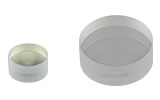
The UFPBSA Low-GDD Broadband Polarizing Beamsplitter provides a reflected beam deviation of 60.0°. The pentagonal shape yields transmitted and reflected beam paths of equal length that are also normal to their respective output faces. Each of the input and output faces of the beamsplitter have a width and height of 12.7 mm, while the long side of the beamsplitter is 22.0 mm. This 22.0 mm is the distance both polarizations travel through the fused silica of the beamsplitter, and this material dispersion will need to be accounted for in ultrafast experiments.

 Zoom
Zoom
Click to Enlarge
Figure G2.1 The hexagonal polarizing beamsplitter separates an unpolarized beam incident from the left into the transmitted p-polarization and reflected s-polarization. The beamsplitter can also be used in the reverse directions.
- Broadband Design Wavelength Range: 720 - 1080 nm
- Extinction Ratio:
- Tp:Ts > 1000:1 (720 - 1080 nm)
- Tp:Ts > 10 000:1 (730 - 1060 nm)
- Tp:Ts > 100 000:1 (800 - 900 nm)
- High Power Handling:
- Pulse: 6.5 J/cm2 (800 nm, 135 ps, 1 kHz, Ø89 µm, 10 000 Pulses)
- Pulse: 19.0 J/cm2 (1064 nm, 10 ns, 10 Hz, Ø230 µm, 1000 Pulses)
- Low Group Delay Dispersion: |GDDp,s| < 40 fs2
- Reflected Beam Deviation: 66.3°
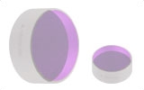
The UFPBS10A High-Power Broadband Polarizing Beamsplitter provides a reflected beam deviation of 66.3°. The hexagonal shape is designed so all four entrance/exit faces are usable, similar to polarizing beamsplitter cubes. This shape also yields transmitted and reflected beam paths of equal length that are normal to their respective output faces. Each of the input and output faces have a height and width of 10.0 mm and the total beam path length for both the s- and p-polarized beams is 15.3 mm.
While the extinction ratio (Tp:Ts) across 720 - 1080 nm is better than 1000:1, particular wavelengths in the center of the band have higher extinction ratios. The extinction ratio graph found on the Graphs tab shows theoretical and measured extinction ratios as a function of wavelength, where Tp:Ts > 100 000:1 is measured from 800 - 900 nm.

 Zoom
Zoom
Click to Enlarge
Figure G3.1 The hexagonal polarizing beamsplitter separates an unpolarized beam incident from the left into the transmitted p-polarization and reflected s-polarization. The beamsplitter can also be used in the reverse directions.
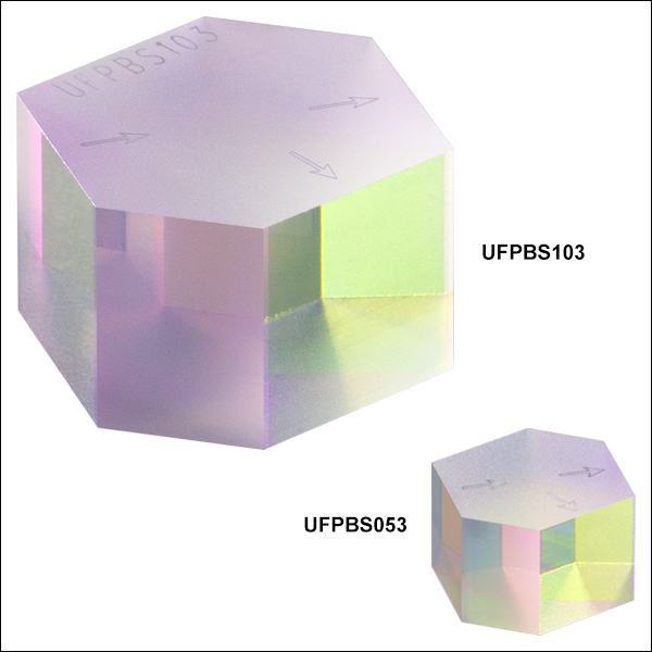
- Broadband Design Wavelength Range: 900 - 1300 nm
- Extinction Ratio:
- Tp:Ts > 1000:1 (900 - 1300 nm)
- Tp:Ts > 10 000:1 (900 - 1250 nm)
- Tp:Ts > 100 000:1 (980 - 1080 nm)
- High Power Handling:
- CW: 200 000 W/cm (51 MW/cm2, 1070 nm, Ø100 µm)
- Pulse: 7.8 J/cm2 (1030 nm, 135 ps, 50 kHz, Ø70 µm, 10 000 Pulses)
- Pulse: 7.4 J/cm2 (1064 nm, 10 ns, 10 Hz, Ø230 µm, 1000 Pulses)
- Low Group Delay Dispersion: |GDDp,s| < 30 fs2
- Reflected Beam Deviation: 67.5°
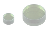
The UFPBS103 and UFPBS053 High-Power Broadband Polarizing Beamsplitter provides a reflected beam deviation of 67.5°. The hexagonal shape is designed so all four entrance/exit faces are usable, similar to polarizing beamsplitter cubes. This shape also yields transmitted and reflected beam paths of equal length that are normal to their respective output faces. Two sizes are available with each of the input and output faces having a height and width of 5.0 mm or 10.0 mm and total beam path length for both the s- and p-polarized beams is 7.5 mm or 15 mm, respectively.
While the extinction ratio (Tp:Ts) across 900 - 1300 nm is better than 1000:1, particular wavelengths in the center of the band have higher extinction ratios. The extinction ratio graph found on the Graphs tab shows theoretical and measured extinction ratios as a function of wavelength, where Tp:Ts > 100 000:1 is measured from 980 - 1080 nm.