 Products Home / Polarization Optics / Polarizers / Film Polarizers / Economy Film Polarizers with Windows
Economy Film Polarizers with Windows

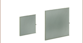
- Polarizing Film Between Two AR-Coated N-BK7 Windows
- Designed for 400 - 700 nm, 600 - 1100 nm, or 1050 - 1700 nm
- Three Sizes: Ø1/2", Ø1", and Ø2"
LPNIRE200-B
(Ø2")
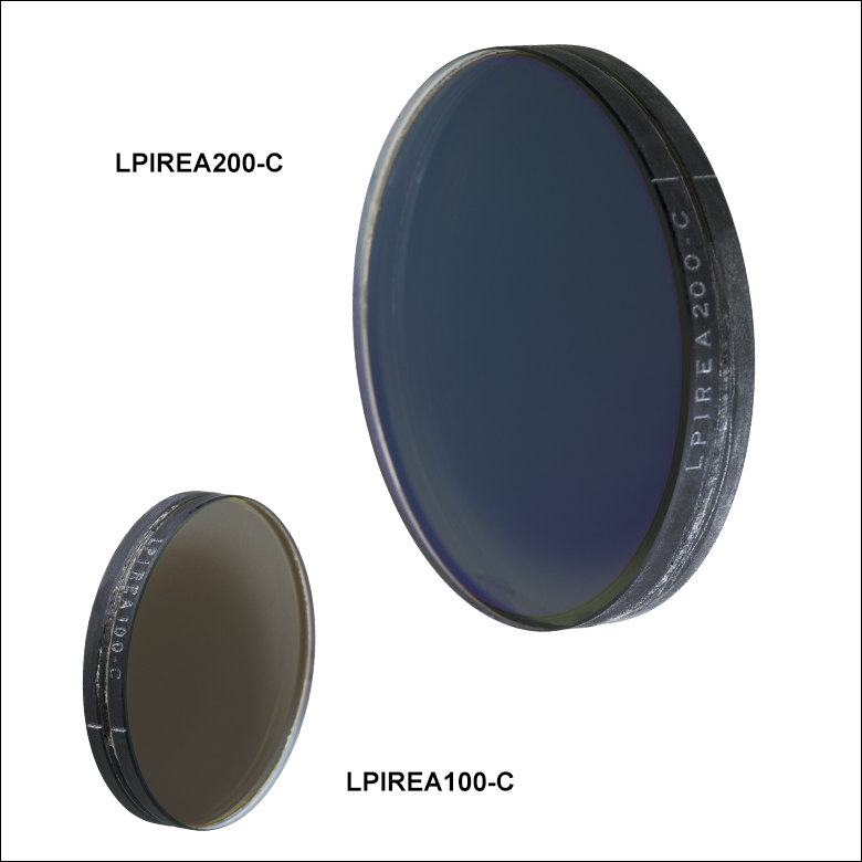
LPIREA100-C
(Ø1")
LPVISE050-A
(Ø1/2")
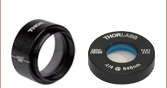
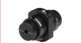
Application Idea
LPVISE050-A Ø1/2" Polarizer
in a PRM05 Optic Mount


Please Wait
| Common Specificationsa | |
|---|---|
| Polarizing Material | Dichroic Film |
| Window Material | N-BK7b |
| Clear Aperture | >90% of Diameter |
| Surface Quality | 60-40 Scratch-Dig |
| Acceptance Angle | ±30° |
| 0 to 40 °C | |
| Beam Deviation | <20 arcmin |
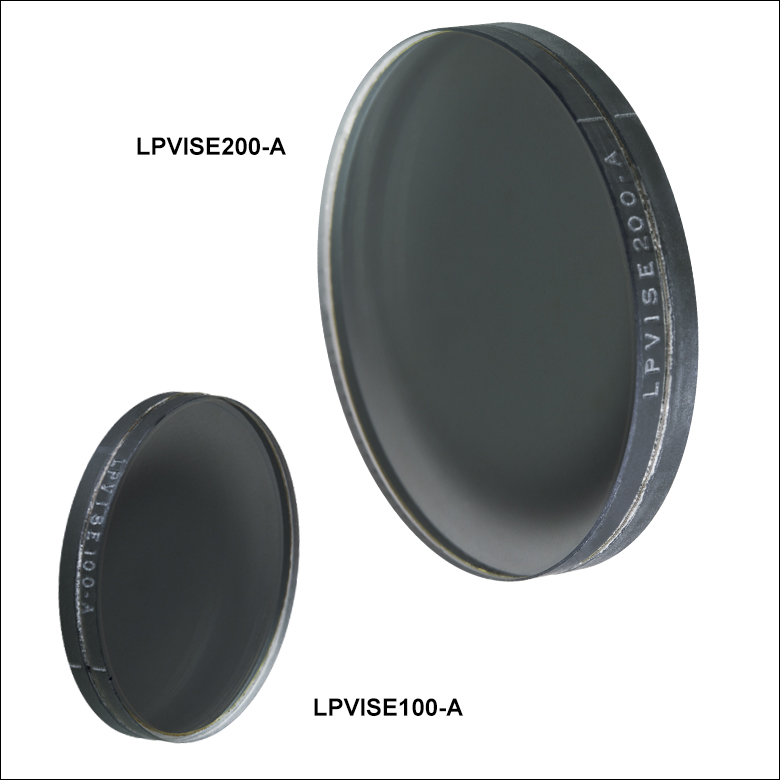
The direction of output polarization is marked on the edge of each polarizer by an engraved line.
Features
- Dichroic Polarizing Film Between Two AR-Coated N-BK7 Windows
- Three Operating Wavelength Ranges Available:
- 400 - 700 nm (-A Designation)
- 600 - 1100 nm (-B Designation)
- 1050 - 1700 nm (-C Designation)
- High Acceptance Angle: ±30°
- Custom Sizes Available; Contact Tech Support for Details
These polarizers have polarization efficiencies in excess of 99% (see the tables below for extinction ratio specifications) and are available in Ø1/2", Ø1", and Ø2" sizes. Featuring a dichroic film sheet, which allows transmission and absorption of polarized light over a specified wavelength range, these polarizers provide high absorption of the rejected polarization, making them ideal for low-power applications. A protective N-BK7 window is epoxied onto each side of the film. In addition, each window has one of three AR coatings deposited on the glass-to-air interface (see the tables below for AR coating specifications). The output polarization direction is marked with a line on the side of each polarizer (see schematic to the right). We also offer 2" x 2" sheets of the dichroic polarizer for 400 - 700 nm without protective windows that are ideal for cutting custom sizes.
These laminated dichroic film polarizers are sensitive to stress when mounting. Overtightening the retaining ring can cause stress-induced birefringence in both the glass and the dichroic film which may reduce the extinction ratio of the optic. To ensure that the polarizer is not loose in the housing, we recommend the use of our Stress-Free Retaining Rings. The use of setscrew-based mounts is not recommended for these polarizers. While the polarizer's surfaces can be cleaned with normal solvents, take care to avoid the polarizer's edge.
| Damage Threshold Specifications | |
|---|---|
| Coating Designation (Item # Suffix) |
Damage Threshold |
| -A | 1 W/cm (532 nm, CW, Ø0.471 mm)a 0.07 J/cm2 (532 nm, 10 Hz, 8 ns, Ø200 µm) |
| -B | 1 W/cm (810 nm, CW, Ø0.004 mm)a 0.15 J/cm2 (810 nm, 10 ns, 10 Hz, Ø0.08 mm) |
| -C | 1 W/cm (1542 nm, CW, Ø0.161 mm)a 0.25 J/cm2 (1540 nm, 10 ns, 10 Hz, Ø242 µm) |
Damage Threshold Data for Thorlabs' Laminated Film Polarizers
The specifications to the right are measured data for Thorlabs' laminated dichroic film polarizers. Damage threshold specifications are constant for all of the polarizers with a given coating designation, regardless of the size of the optic.
Laser Induced Damage Threshold Tutorial
The following is a general overview of how laser induced damage thresholds are measured and how the values may be utilized in determining the appropriateness of an optic for a given application. When choosing optics, it is important to understand the Laser Induced Damage Threshold (LIDT) of the optics being used. The LIDT for an optic greatly depends on the type of laser you are using. Continuous wave (CW) lasers typically cause damage from thermal effects (absorption either in the coating or in the substrate). Pulsed lasers, on the other hand, often strip electrons from the lattice structure of an optic before causing thermal damage. Note that the guideline presented here assumes room temperature operation and optics in new condition (i.e., within scratch-dig spec, surface free of contamination, etc.). Because dust or other particles on the surface of an optic can cause damage at lower thresholds, we recommend keeping surfaces clean and free of debris. For more information on cleaning optics, please see our Optics Cleaning tutorial.
Testing Method
Thorlabs' LIDT testing is done in compliance with ISO/DIS 11254 and ISO 21254 specifications.
First, a low-power/energy beam is directed to the optic under test. The optic is exposed in 10 locations to this laser beam for 30 seconds (CW) or for a number of pulses (pulse repetition frequency specified). After exposure, the optic is examined by a microscope (~100X magnification) for any visible damage. The number of locations that are damaged at a particular power/energy level is recorded. Next, the power/energy is either increased or decreased and the optic is exposed at 10 new locations. This process is repeated until damage is observed. The damage threshold is then assigned to be the highest power/energy that the optic can withstand without causing damage. A histogram such as that below represents the testing of one BB1-E02 mirror.

The photograph above is a protected aluminum-coated mirror after LIDT testing. In this particular test, it handled 0.43 J/cm2 (1064 nm, 10 ns pulse, 10 Hz, Ø1.000 mm) before damage.

| Example Test Data | |||
|---|---|---|---|
| Fluence | # of Tested Locations | Locations with Damage | Locations Without Damage |
| 1.50 J/cm2 | 10 | 0 | 10 |
| 1.75 J/cm2 | 10 | 0 | 10 |
| 2.00 J/cm2 | 10 | 0 | 10 |
| 2.25 J/cm2 | 10 | 1 | 9 |
| 3.00 J/cm2 | 10 | 1 | 9 |
| 5.00 J/cm2 | 10 | 9 | 1 |
According to the test, the damage threshold of the mirror was 2.00 J/cm2 (532 nm, 10 ns pulse, 10 Hz, Ø0.803 mm). Please keep in mind that these tests are performed on clean optics, as dirt and contamination can significantly lower the damage threshold of a component. While the test results are only representative of one coating run, Thorlabs specifies damage threshold values that account for coating variances.
Continuous Wave and Long-Pulse Lasers
When an optic is damaged by a continuous wave (CW) laser, it is usually due to the melting of the surface as a result of absorbing the laser's energy or damage to the optical coating (antireflection) [1]. Pulsed lasers with pulse lengths longer than 1 µs can be treated as CW lasers for LIDT discussions.
When pulse lengths are between 1 ns and 1 µs, laser-induced damage can occur either because of absorption or a dielectric breakdown (therefore, a user must check both CW and pulsed LIDT). Absorption is either due to an intrinsic property of the optic or due to surface irregularities; thus LIDT values are only valid for optics meeting or exceeding the surface quality specifications given by a manufacturer. While many optics can handle high power CW lasers, cemented (e.g., achromatic doublets) or highly absorptive (e.g., ND filters) optics tend to have lower CW damage thresholds. These lower thresholds are due to absorption or scattering in the cement or metal coating.

LIDT in linear power density vs. pulse length and spot size. For long pulses to CW, linear power density becomes a constant with spot size. This graph was obtained from [1].

Pulsed lasers with high pulse repetition frequencies (PRF) may behave similarly to CW beams. Unfortunately, this is highly dependent on factors such as absorption and thermal diffusivity, so there is no reliable method for determining when a high PRF laser will damage an optic due to thermal effects. For beams with a high PRF both the average and peak powers must be compared to the equivalent CW power. Additionally, for highly transparent materials, there is little to no drop in the LIDT with increasing PRF.
In order to use the specified CW damage threshold of an optic, it is necessary to know the following:
- Wavelength of your laser
- Beam diameter of your beam (1/e2)
- Approximate intensity profile of your beam (e.g., Gaussian)
- Linear power density of your beam (total power divided by 1/e2 beam diameter)
Thorlabs expresses LIDT for CW lasers as a linear power density measured in W/cm. In this regime, the LIDT given as a linear power density can be applied to any beam diameter; one does not need to compute an adjusted LIDT to adjust for changes in spot size, as demonstrated by the graph to the right. Average linear power density can be calculated using the equation below.

The calculation above assumes a uniform beam intensity profile. You must now consider hotspots in the beam or other non-uniform intensity profiles and roughly calculate a maximum power density. For reference, a Gaussian beam typically has a maximum power density that is twice that of the uniform beam (see lower right).
Now compare the maximum power density to that which is specified as the LIDT for the optic. If the optic was tested at a wavelength other than your operating wavelength, the damage threshold must be scaled appropriately. A good rule of thumb is that the damage threshold has a linear relationship with wavelength such that as you move to shorter wavelengths, the damage threshold decreases (i.e., a LIDT of 10 W/cm at 1310 nm scales to 5 W/cm at 655 nm):

While this rule of thumb provides a general trend, it is not a quantitative analysis of LIDT vs wavelength. In CW applications, for instance, damage scales more strongly with absorption in the coating and substrate, which does not necessarily scale well with wavelength. While the above procedure provides a good rule of thumb for LIDT values, please contact Tech Support if your wavelength is different from the specified LIDT wavelength. If your power density is less than the adjusted LIDT of the optic, then the optic should work for your application.
Please note that we have a buffer built in between the specified damage thresholds online and the tests which we have done, which accommodates variation between batches. Upon request, we can provide individual test information and a testing certificate. The damage analysis will be carried out on a similar optic (customer's optic will not be damaged). Testing may result in additional costs or lead times. Contact Tech Support for more information.
Pulsed Lasers
As previously stated, pulsed lasers typically induce a different type of damage to the optic than CW lasers. Pulsed lasers often do not heat the optic enough to damage it; instead, pulsed lasers produce strong electric fields capable of inducing dielectric breakdown in the material. Unfortunately, it can be very difficult to compare the LIDT specification of an optic to your laser. There are multiple regimes in which a pulsed laser can damage an optic and this is based on the laser's pulse length. The highlighted columns in the table below outline the relevant pulse lengths for our specified LIDT values.
Pulses shorter than 10-9 s cannot be compared to our specified LIDT values with much reliability. In this ultra-short-pulse regime various mechanics, such as multiphoton-avalanche ionization, take over as the predominate damage mechanism [2]. In contrast, pulses between 10-7 s and 10-4 s may cause damage to an optic either because of dielectric breakdown or thermal effects. This means that both CW and pulsed damage thresholds must be compared to the laser beam to determine whether the optic is suitable for your application.
| Pulse Duration | t < 10-9 s | 10-9 < t < 10-7 s | 10-7 < t < 10-4 s | t > 10-4 s |
|---|---|---|---|---|
| Damage Mechanism | Avalanche Ionization | Dielectric Breakdown | Dielectric Breakdown or Thermal | Thermal |
| Relevant Damage Specification | No Comparison (See Above) | Pulsed | Pulsed and CW | CW |
When comparing an LIDT specified for a pulsed laser to your laser, it is essential to know the following:

LIDT in energy density vs. pulse length and spot size. For short pulses, energy density becomes a constant with spot size. This graph was obtained from [1].
- Wavelength of your laser
- Energy density of your beam (total energy divided by 1/e2 area)
- Pulse length of your laser
- Pulse repetition frequency (prf) of your laser
- Beam diameter of your laser (1/e2 )
- Approximate intensity profile of your beam (e.g., Gaussian)
The energy density of your beam should be calculated in terms of J/cm2. The graph to the right shows why expressing the LIDT as an energy density provides the best metric for short pulse sources. In this regime, the LIDT given as an energy density can be applied to any beam diameter; one does not need to compute an adjusted LIDT to adjust for changes in spot size. This calculation assumes a uniform beam intensity profile. You must now adjust this energy density to account for hotspots or other nonuniform intensity profiles and roughly calculate a maximum energy density. For reference a Gaussian beam typically has a maximum energy density that is twice that of the 1/e2 beam.
Now compare the maximum energy density to that which is specified as the LIDT for the optic. If the optic was tested at a wavelength other than your operating wavelength, the damage threshold must be scaled appropriately [3]. A good rule of thumb is that the damage threshold has an inverse square root relationship with wavelength such that as you move to shorter wavelengths, the damage threshold decreases (i.e., a LIDT of 1 J/cm2 at 1064 nm scales to 0.7 J/cm2 at 532 nm):

You now have a wavelength-adjusted energy density, which you will use in the following step.
Beam diameter is also important to know when comparing damage thresholds. While the LIDT, when expressed in units of J/cm², scales independently of spot size; large beam sizes are more likely to illuminate a larger number of defects which can lead to greater variances in the LIDT [4]. For data presented here, a <1 mm beam size was used to measure the LIDT. For beams sizes greater than 5 mm, the LIDT (J/cm2) will not scale independently of beam diameter due to the larger size beam exposing more defects.
The pulse length must now be compensated for. The longer the pulse duration, the more energy the optic can handle. For pulse widths between 1 - 100 ns, an approximation is as follows:

Use this formula to calculate the Adjusted LIDT for an optic based on your pulse length. If your maximum energy density is less than this adjusted LIDT maximum energy density, then the optic should be suitable for your application. Keep in mind that this calculation is only used for pulses between 10-9 s and 10-7 s. For pulses between 10-7 s and 10-4 s, the CW LIDT must also be checked before deeming the optic appropriate for your application.
Please note that we have a buffer built in between the specified damage thresholds online and the tests which we have done, which accommodates variation between batches. Upon request, we can provide individual test information and a testing certificate. Contact Tech Support for more information.
[1] R. M. Wood, Optics and Laser Tech. 29, 517 (1998).
[2] Roger M. Wood, Laser-Induced Damage of Optical Materials (Institute of Physics Publishing, Philadelphia, PA, 2003).
[3] C. W. Carr et al., Phys. Rev. Lett. 91, 127402 (2003).
[4] N. Bloembergen, Appl. Opt. 12, 661 (1973).

In order to illustrate the process of determining whether a given laser system will damage an optic, a number of example calculations of laser induced damage threshold are given below. For assistance with performing similar calculations, we provide a spreadsheet calculator that can be downloaded by clicking the LIDT Calculator button. To use the calculator, enter the specified LIDT value of the optic under consideration and the relevant parameters of your laser system in the green boxes. The spreadsheet will then calculate a linear power density for CW and pulsed systems, as well as an energy density value for pulsed systems. These values are used to calculate adjusted, scaled LIDT values for the optics based on accepted scaling laws. This calculator assumes a Gaussian beam profile, so a correction factor must be introduced for other beam shapes (uniform, etc.). The LIDT scaling laws are determined from empirical relationships; their accuracy is not guaranteed. Remember that absorption by optics or coatings can significantly reduce LIDT in some spectral regions. These LIDT values are not valid for ultrashort pulses less than one nanosecond in duration.
Figure 71A A Gaussian beam profile has about twice the maximum intensity of a uniform beam profile.
CW Laser Example
Suppose that a CW laser system at 1319 nm produces a 0.5 W Gaussian beam that has a 1/e2 diameter of 10 mm. A naive calculation of the average linear power density of this beam would yield a value of 0.5 W/cm, given by the total power divided by the beam diameter:
However, the maximum power density of a Gaussian beam is about twice the maximum power density of a uniform beam, as shown in Figure 71A. Therefore, a more accurate determination of the maximum linear power density of the system is 1 W/cm.
An AC127-030-C achromatic doublet lens has a specified CW LIDT of 350 W/cm, as tested at 1550 nm. CW damage threshold values typically scale directly with the wavelength of the laser source, so this yields an adjusted LIDT value:
The adjusted LIDT value of 350 W/cm x (1319 nm / 1550 nm) = 298 W/cm is significantly higher than the calculated maximum linear power density of the laser system, so it would be safe to use this doublet lens for this application.
Pulsed Nanosecond Laser Example: Scaling for Different Pulse Durations
Suppose that a pulsed Nd:YAG laser system is frequency tripled to produce a 10 Hz output, consisting of 2 ns output pulses at 355 nm, each with 1 J of energy, in a Gaussian beam with a 1.9 cm beam diameter (1/e2). The average energy density of each pulse is found by dividing the pulse energy by the beam area:

As described above, the maximum energy density of a Gaussian beam is about twice the average energy density. So, the maximum energy density of this beam is ~0.7 J/cm2.
The energy density of the beam can be compared to the LIDT values of 1 J/cm2 and 3.5 J/cm2 for a BB1-E01 broadband dielectric mirror and an NB1-K08 Nd:YAG laser line mirror, respectively. Both of these LIDT values, while measured at 355 nm, were determined with a 10 ns pulsed laser at 10 Hz. Therefore, an adjustment must be applied for the shorter pulse duration of the system under consideration. As described on the previous tab, LIDT values in the nanosecond pulse regime scale with the square root of the laser pulse duration:
This adjustment factor results in LIDT values of 0.45 J/cm2 for the BB1-E01 broadband mirror and 1.6 J/cm2 for the Nd:YAG laser line mirror, which are to be compared with the 0.7 J/cm2 maximum energy density of the beam. While the broadband mirror would likely be damaged by the laser, the more specialized laser line mirror is appropriate for use with this system.
Pulsed Nanosecond Laser Example: Scaling for Different Wavelengths
Suppose that a pulsed laser system emits 10 ns pulses at 2.5 Hz, each with 100 mJ of energy at 1064 nm in a 16 mm diameter beam (1/e2) that must be attenuated with a neutral density filter. For a Gaussian output, these specifications result in a maximum energy density of 0.1 J/cm2. The damage threshold of an NDUV10A Ø25 mm, OD 1.0, reflective neutral density filter is 0.05 J/cm2 for 10 ns pulses at 355 nm, while the damage threshold of the similar NE10A absorptive filter is 10 J/cm2 for 10 ns pulses at 532 nm. As described on the previous tab, the LIDT value of an optic scales with the square root of the wavelength in the nanosecond pulse regime:
This scaling gives adjusted LIDT values of 0.08 J/cm2 for the reflective filter and 14 J/cm2 for the absorptive filter. In this case, the absorptive filter is the best choice in order to avoid optical damage.
Pulsed Microsecond Laser Example
Consider a laser system that produces 1 µs pulses, each containing 150 µJ of energy at a repetition rate of 50 kHz, resulting in a relatively high duty cycle of 5%. This system falls somewhere between the regimes of CW and pulsed laser induced damage, and could potentially damage an optic by mechanisms associated with either regime. As a result, both CW and pulsed LIDT values must be compared to the properties of the laser system to ensure safe operation.
If this relatively long-pulse laser emits a Gaussian 12.7 mm diameter beam (1/e2) at 980 nm, then the resulting output has a linear power density of 5.9 W/cm and an energy density of 1.2 x 10⁻⁴ J/cm2 per pulse. This can be compared to the LIDT values for a WPQ10E-980 polymer zero-order quarter-wave plate, which are 5 W/cm for CW radiation at 810 nm and 5 J/cm2 for a 10 ns pulse at 810 nm. As before, the CW LIDT of the optic scales linearly with the laser wavelength, resulting in an adjusted CW value of 6 W/cm at 980 nm. On the other hand, the pulsed LIDT scales with the square root of the laser wavelength and the square root of the pulse duration, resulting in an adjusted value of 55 J/cm2 for a 1 µs pulse at 980 nm. The pulsed LIDT of the optic is significantly greater than the energy density of the laser pulse, so individual pulses will not damage the wave plate. However, the large average linear power density of the laser system may cause thermal damage to the optic, much like a high-power CW beam.
| Posted Comments: | |
Gwan woo Lee
(posted 2025-02-11 22:04:38.263) I'm using the LPVISE100-A, but I noticed that the transmitted beam shifts or rotates when the linear polarizer is rotated. Do you know the flatness specification of the LPVISE100-A? cdolbashian
(posted 2025-02-20 04:57:15.0) Thank you for contacting Thorlabs. The parallelism of LPVISE100-A is <20 arcmin, which can explain the beam shift and rotation you observed in the transmitted beam. The flatness is not the standard specification, I have contacted you via email to share the typical flatness value. Andrey Kuznetsov
(posted 2024-07-24 22:28:50.067) What is the tolerance spec in degrees of the notch/line that indicates the polarization axis? We have a product where the polarization axis is ~12.5deg offset from the notch. Verified using multiple other polarizers, LCD screens. cdolbashian
(posted 2024-08-01 03:41:02.0) Thank you for contacting Thorlabs. The engraved line position is just an indication for the polarization axis, the expected tolerance is about +/-5°, but it is not the spec we can guarantee. We will contact you directly to follow up. Hoonsup Kim
(posted 2024-03-26 11:52:05.67) Please let me know how to clean LPVISE050-A. Due to a human finger touch, there is some debris on the surface of the product. Lens tissue paper and Alcohol are suitable for cleaning of it? Otherwise, other ways? cdolbashian
(posted 2024-03-29 02:02:25.0) Thank you for contacting Thorlabs. The surface of LPVISE050-A can be cleaned with normal solvents (such as Lens tissue paper and Alcohol), but please take care to avoid the edge. The Cleaning Procedure can be found at the following link: https://www.thorlabs.com/newgrouppage9.cfm?objectgroup_id=9025. Shenlei Zhu
(posted 2020-09-24 17:06:52.067) We have bought two Polarizers of LPVISE100-A, and we test the transmission of them with the P-Polarized light, but we found that the results are deviated from your datasheet, therefore we want to know your specific measurement method, which would be much helpful for us. Thank you~ YLohia
(posted 2020-09-25 09:15:35.0) Thank you for contacting Thorlabs. Please note that the transmission curve on website is typical and there will be deviations from unit to unit. We have reached out to you directly with details about our test setup. Philipp Schlömer
(posted 2020-01-24 04:16:43.793) Would also a size of 0.75'' for the LPVISxxx-A be possible? (Or anything else between 1'' and 0.5'') YLohia
(posted 2020-01-24 09:40:03.0) Thank you for contacting Thorlabs. Custom optics can be requested by emailing techsupport@thorlabs.com. We will reach out to you directly to discuss this quote. user
(posted 2019-05-16 13:26:03.06) I use the LPNIRE100-B polarizer. I would like to know the degree of polarization of the transmitted light, if incident light is totally unpolarized. YLohia
(posted 2019-05-16 03:21:40.0) Hello, the degree of polarization of a truly unpolarized source after traversing through a linear polarizer is comparable to its polarization extinction ratio (PER) spec. Your polarizer is specified for a PER of >1000:1 for the 600-950nm range. Assuming that your light source is within this wavelength range, the power contained in the light along the polarization axis will be at least 1000x that of the power contained in the orthogonal axis after passing through the optic. Thus, your DOP will be at least 1 - (1/PER) = 0.999. User
(posted 2019-02-28 10:49:31.607) I would like to buy a LPNIRE100-B but I've read that "these polarizers are not designed for imaging applications due to internal scatter and relatively larger wavefront distortion". Could you explain a little bit further?
I am planning to put this polarizer on my collimated light source and switch between 2 polarizations.
I am worried about the term "relatively larger". Will it affect a lot the collimation of my beam? llamb
(posted 2019-03-04 10:18:34.0) Thank you for your feedback. These polarizers will introduce internal scattering that will result in reduced clarity for imaging applications. If you are solely sending a collimated beam through this polarizer without any imaging information, image clarity will not be critical and this polarizer will not significantly impact your collimation. I have reached out to you directly to discuss further. clemens_rueck
(posted 2018-12-11 14:10:41.827) we have bought two Polarizing Filter LPNIRE050-B which have a specification of > 30 dB (600 - 950 nm).
Actual measurements showed an extinction ratio of about 18 dB at 633 nm (to ensure that the input signal is well polarized we "crossed" these two filters).
Can you explain this?
Best Regards,
Clemens Rück. llamb
(posted 2018-12-14 09:40:23.0) Hello Clemens, thank you for your feedback. When measuring polarizers' extinction ratios, it is important that your input beam is polarized to a high extinction ratio to begin with. Also, it is helpful to keep your power sensor or detector far apart from the polarizers to avoid scattering effects that raise your minimum power and lower your measured extinction ratio. I have reached out to you by email to troubleshoot further. sdacha
(posted 2018-11-15 21:29:11.47) I purchased two of the LPNIRE100-B polarizers to adjust the power going into my system. My laser is a 1064 nm, 1 ns, 138 uJ and 1 kHz system. I wasn't too worried about the damage, but the wavefront distortion after passing through even one polarizer is pretty high. I would like as low wavefront distortion as possible, even after passing through two polarizers. What models do you guys suggest as alternatives to the LPNIRE100-B? YLohia
(posted 2018-11-26 11:22:00.0) Hello, thank you for contacting Thorlabs. Is there any particular reason that you're not using neutral density filters to reduce the power going into your system? We have many options here (including variable filters): https://www.thorlabs.com/navigation.cfm?guide_ID=2185
That being said, if you still want to stick to two polarizers, we recommend looking into the unmounted LPVIS100 nanoparticle polarizer. This has a transmitted wavefront error spec of < lambda/4 at 633nm, which is better than the < 1.5 lambda that the LPNIRE100-B offers. yannick.folwill
(posted 2018-08-23 11:14:26.69) I am using the LPVISE100-A in a rotation stage but I observe the transmitted beam has a displacement depending on the rotation of the polarizer. the angle of displacement changes when using a different polarizer (also LPVISE100-A). Is this a property of the polarizer or am I just not mounting it flat enough? The displacement angles are about 0.1° and 1° for the two polarizers I tried. llamb
(posted 2018-08-31 09:34:31.0) Thank you for contacting Thorlabs. These economy polarizers may have some small wedge that can be causing beam deviation. Deviation may also be attributed to a non-normal angle of incidence of your beam on the polarizer, or perhaps a wobble of the rotation stage as well. I have reached out to you directly to troubleshoot further. user
(posted 2018-08-02 23:03:48.133) Presentation says that ""dichroic" film is used . I am interested to know what performance is "dichroic"? It seems spectra is flat. YLohia
(posted 2018-08-06 08:39:58.0) For these polarizers, the term "dichroic" refers to the fact that the film absorbs the unwanted polarization states while transmitting the chosen linear state. It does not refer to spectral behavior as the name might imply. w.husson
(posted 2018-03-20 13:57:24.9) Hello,
I saw you give an operating range for the temperature from 0 to 70°C. The polarizer film alone is given from -50°C to 70°C, I think the BK7 is perfectly stable, Why is there a difference? due to AR coating?
I need a -20 to 50°C range.
Best regards,
Wilfrid YLohia
(posted 2018-03-28 08:26:29.0) Hello Wilfrid, thank you for contacting Thorlabs. While some units across the product line are able to withstand the higher temperatures, the safe operating temperature range is 0 to 40 C across all the economy film polarizers. For LPVISE, the upper range (40 C) is an absolute limit due to the bonding of the film to the substrate. The lower range may be somewhat flexible, depending on the performance needed and other conditions, but we cannot guarantee anything. My apologies for any confusion caused by the previous note. We have revised the previous note to make this more clear. chao.he
(posted 2018-03-16 12:35:17.777) I found that the Economy Film Polarizers, (600 - 1100 nm) have different strips on it (or thickness)? it will show on CCD without imaging it, is there any way to deal with it? (400-700nm one works extremely well) llamb
(posted 2018-03-30 01:32:47.0) Hello, thank you for contacting Thorlabs. The -B coated (600 - 1100 nm) economy film polarizers do have a different anti-reflection coating than the -A coated (400 - 700 nm) polarizers, as well as a different polarizing film. The -B coated polarizers also do not completely absorb the rejected polarization, so perhaps you are seeing some of this reflected light. I will reach out to you directly to discuss your application further. panecki
(posted 2017-09-28 12:36:50.043) Why Economy Film Polarizers, (600 - 1100 nm)
have different thickness.? On the extinction figure there is one version only ,
Sincerely Yours
P.Panecki nbayconich
(posted 2017-10-10 08:26:55.0) Thank you for contacting Thorlabs. The film thickness of the 600nm - 1100nm economy film polarizers is the same for each size. The thickness of the substrate material increases with the diameter of the polarizer to prevent chipping or damage. I will reach out to you directly. fenghao_xu
(posted 2017-08-04 17:28:51.103) Hi, I bought one LPNIRE100-B with RSP1/M rotation mount. However I observe the pass beams have displacement around a ~6mm diameter circle at ~50cm behind when rotating the polarizers. How can I fix that problem? tfrisch
(posted 2017-09-05 04:22:39.0) Hello, thank you for contacting Thorlabs. I will reach out to you directly to characterize this displacement. Linear and angular displacements would have different causes. inzenith
(posted 2017-06-21 16:22:56.457) Hello, I bought LPVISE100-A and LPNIRE100-B polarizer. but I observe both refracted and passed beams have displacement around a circle wile rotating the polarizers.how can i solve this problem? tfrisch
(posted 2017-06-27 11:48:58.0) Hello, thank you for contacting Thorlabs. I will reach out to you directly about how this polarizer is mounted. It would also be helpful to know if the size of the dispalced circle is dependent on the distance from the optic to where the circle is observed; that is, does the beam precess in a cone or a cylinder? dr_mohammed_temimi
(posted 2017-06-14 12:44:30.347) please i want to ask you about it
how can ı know the input and output direction of it
please explian that to me
thanks nbayconich
(posted 2017-06-14 05:32:46.0) Thank you for contacting Thorlabs. The orientation of the black etched mark on the side of the polarizer indicates the transmission axis of the polarizer. A Techsupport representative will contact you directly. jeeyeony
(posted 2016-07-12 03:28:33.34) Hello. I am optic engineer of LIGnex1 in Korea
I contact you for temperature range of polarizer(operational & storage)
Expecting a response to this letter! tfrisch
(posted 2016-08-25 08:42:38.49) Hello Jeeyeony, thank you for contacting Thorlabs. The operational and storage temperature is 0°C to 70°C. I have contacted you directly with this information as well. -Tyler at Thorlabs USA
Edit: while some units will have variation in temperature handling, 0°C to 40°C is a more representative storage and operating temperature range for these economy film polarizers. petr.bouchal
(posted 2016-01-19 12:30:04.513) Hello, I appreciate additional information on acceptance angles of your linear polarizers. Are the values of the extinction ratio valid within the whole cone given by acceptance angle?
Thank, you.
Sincerely,
Petr. besembeson
(posted 2016-01-19 01:51:51.0) Response from Bweh at Thorlabs USA: Due to the dependence of the reflectivity and transmission of the AR coating to angle of incidence (<0.5% at 0° AOI), and the dependence of the Fresnel reflections/transmission with angle of incidence, the extinction ratio will not be the same over the acceptance angle. You are correct we will look into providing more information/data regarding this on these pages. IGKIOU
(posted 2014-10-02 16:27:08.47) Hi, are there larger versions of the visible polarizers available? I would be particularly interested in a 3'' round version of LPVISE200-A. Thank you in advance. besembeson
(posted 2014-10-09 12:51:19.0) Response from Bweh at Thorlabs: We can provide this to you as a custom item. I will follow up via email with a quotation. parksj
(posted 2013-11-04 20:35:23.713) Hello
We have purchased the linear polarizers 'LPNIRE100-B' to adjust the output power of Nd-Yag pulsed laser. However, when i placed the polarizer in the beam path of the pulsed laser, the polarizser burned out and colored black.
The used Nd-Yag laser spec is shown below:
pulse duration ~10 nsec
rep. rate: 20 Hz
energy per pulse < 50mJ
output wavelength 1064nm
Would you let me know why it burned and recommend the proper polarizers or components to adjust the output power of the Nd-Yag laser?
Best regards,
Seongjun Park tcohen
(posted 2013-11-14 04:14:33.0) Response from Tim at Thorlabs: When using a polarizer for attenuation with a source of this power it would be better to use a non-absorptive polarizer for the rejection. A calcite based polarizer would be more suited for this application. user
(posted 2013-08-01 18:58:11.387) Hi!
I noticed when using the LPVISE100-A for 785nm that the optical axis (or angles at minimum/maximum transmission) is different dependent on from which side the light enters. Is this as expected? tcohen
(posted 2013-08-05 11:11:00.0) Response from Tim at Thorlabs: This product will not act as a polarizer at 785nm. The LPNIRE100-B would be more suitable (please see the graphs for ER plots). I'd like to discuss your measurement with you but I see you did not leave any contact information. Please contact us at techsupport@thorlabs.com to continue this discussion. christian.b.schmidt
(posted 2013-07-10 07:42:36.723) Do you have any information about the beam displacement? (Polarizer turning from 0-45-90-180 deg?)
And would the polarizer be suitable for 700-900nm for a laser 100fs, total power of ~1W, 76MHz, beam diameter ~3mm? tcohen
(posted 2013-08-05 11:10:00.0) Response from Tim at Thorlabs: This would likely be damaged by your fs laser. A Glan-Taylor/Laser/Thompson would be more suitable. spotnis
(posted 2013-01-24 13:01:12.217) Can I obtain data for transmission and polarization extinction for 780nm? cdaly
(posted 2013-01-29 17:40:00.0) Response from Chris at Thorlabs: Thank you for using our web feedback. The transmission is going to be roughly 90% and the extinction ratio will be less than 10:1. The LPVIS series of polarizers will have much better performance, as these are specified at 780 nm to have an extinction ratio of greater than 100,000:1. sharrell
(posted 2012-01-13 08:10:00.0) Thank you for your feedback. We do not recommend our economy polarizers for high-power applications. Regarding the transmission values, the value indicated on the curve is for a linearly polarized input, while the value on the pdf drawing and specifications is for an unpolarized input, leading to the 50% discrepancy. We will clarify this on our website. francisco1591
(posted 2012-01-03 11:50:59.0) What is the laser power tolerance of the economy linear polarizers??
Why is the avg transmission 38% according to the AUto-CAD drawings and specs, while is about 70% according to the transmission curves |
Polarizer Selection Guide
Thorlabs offers a diverse range of polarizers, including wire grid, film, calcite, alpha-BBO, rutile, and beamsplitting polarizers. Collectively, our line of wire grid polarizers offers coverage from the visible range to the beginning of the Far-IR range. Our nanoparticle linear film polarizers provide extinction ratios as high as 100 000:1. Alternatively, our other film polarizers offer an affordable solution for polarizing light from the visible to the Near-IR. Next, our beamsplitting polarizers allow for use of the reflected beam, as well as the more completely polarized transmitted beam. Finally, our alpha-BBO (UV), calcite (visible to Near-IR), rutile (Near-IR to Mid-IR), and yttrium orthovanadate (YVO4) (Near-IR to Mid-IR) polarizers each offer an exceptional extinction ratio of 100 000:1 within their respective wavelength ranges.
To explore the available types, wavelength ranges, extinction ratios, transmission, and available sizes for each polarizer category, click More [+] in the appropriate row below.
| Wire Grid Polarizers |
|---|
| Film Polarizers |
|---|


| Beamsplitting Polarizers |
|---|


| alpha-BBO Polarizers |
|---|
| Calcite Polarizers |
|---|
| Quartz Polarizers |
|---|
| Magnesium Fluoride Polarizers |
|---|
| Yttrium Orthovanadate (YVO4) Polarizers |
|---|
| Rutile Polarizers |
|---|

 Zoom
Zoom| Item # | |||
|---|---|---|---|
| Operating Wavelength Range |
400 - 700 nm | ||
| AR Coating Range | 350 - 700 nm | ||
| Reflectance over Coating Range (Avg.) |
<0.5% at 0° AOI | ||
| AR Coating Curve |  |
||
| Extinction Ratioa,b | >100:1 (400 - 500 nm) >1000:1 (500 - 700 nm) >5000:1 (530 - 690 nm) |
||
| Size | Ø1/2" | Ø1" | Ø2" |
| Thickness | 2.1 mm | 3.3 mm | 6.5 mm |
| Dimensional Tolerance | ±0.2 mm | ||
| Damage Threshold | 1 W/cm (532 nm, CW, Ø0.471 mm)c 0.07 J/cm2 (532 nm, 10 Hz, 8 ns, Ø200 µm) |
||
| Transmitted Wavefront Distortion | λ at 633 nm | ||
Click to Enlarge
Click Here for Data
The graph above shows the measured transmission of unpolarized light as well as that of polarized light aligned with the polarization axis of the optic. The shaded region represents the specified operating wavelength range of the polarizer.
These dichroic film polarizers, which are optimized for use in the 400 - 700 nm range, have an AR coating for the 350 - 700 nm range deposited on the air-to-glass interface of each window. They offer an average transmission of 38% for unpolarized light over their operating wavelength range. The direction of the output polarization is marked on the edge of each polarizer.

 Zoom
Zoom| Item # | |||
|---|---|---|---|
| Operating Wavelength Range |
600 - 1100 nm | ||
| AR Coating Range | 650 - 1050 nm | ||
| Reflectance over Coating Range (Avg.) |
<0.5% at 0° AOI | ||
| AR Coating Curve | 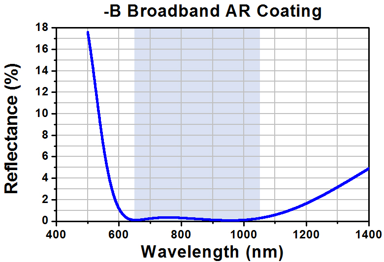 |
||
| Extinction Ratioa,b | >1000:1 (600 - 950 nm) >400:1 (600 - 1100 nm) |
||
| Size | Ø1/2" | Ø1" | Ø2" |
| Thickness | 2.1 mm | 3.3 mm | 6.5 mm |
| Dimensional Tolerance | ±0.2 mm | ||
| Damage Threshold | 1 W/cm (810 nm, CW, Ø0.004 mm)c 0.15 J/cm2 (810 nm, 10 ns, 10 Hz, Ø0.08 mm) |
||
| Transmitted Wavefront Distortion | 1.5λ at 633 nm | ||
Click to Enlarge
Click Here for Data
The graph above shows the measured transmission of unpolarized light as well as that of polarized light aligned with the polarization axis of the optic. The shaded region represents the specified operating wavelength range of the polarizer.
These dichroic film polarizers, which are optimized for use in the 600 - 1100 nm range, have an AR coating for the 650 - 1050 nm range deposited on the air-to-glass interface of each window. They offer an average transmission of 43% for unpolarized light over their operating wavelength range. The NIR polarizers sold here do not completely absorb the rejected polarization. On average, they reflect 25% of the rejected light. The direction of the output polarization is marked on the edge of each polarizer.
Note: these polarizers are not designed for imaging applications due to internal scatter and relatively larger wavefront distortion. For polarizers with minimal scatter, please see our Nanoparticle Linear Film Polarizers.

 Zoom
Zoom| Item # | |||
|---|---|---|---|
| Operating Wavelength Range |
1050 - 1700 nm | ||
| AR Coating Range | 1050 - 1700 nm | ||
| Reflectance over Coating Range (Avg.) |
<0.5% at 0° AOI | ||
| AR Coating Curve | 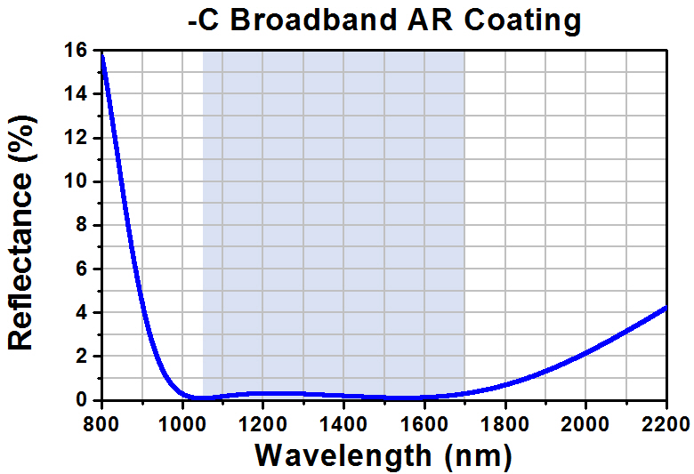 |
||
| Extinction Ratioa,b | >1000:1 (1050 - 1400 nm) >2000:1 (1400 - 1700 nm) |
||
| Size | Ø1/2" | Ø1" | Ø2" |
| Thickness | 2.5 mm | 3.7 mm | 6.9 mm |
| Dimensional Tolerance | ±0.3 mm | ||
| Damage Threshold | 1 W/cm (1542 nm, CW, Ø0.161 mm)c 0.25 J/cm2 (1540 nm, 10 ns, 10 Hz, Ø242 µm) |
||
| Transmitted Wavefront Distortion | λ at 633 nm | ||
Click to Enlarge
Click Here for Data
The graph above shows the measured transmission of unpolarized light as well as that of polarized light aligned with the polarization axis of the optic. The shaded region represents the specified operating wavelength range of the polarizer.
These dichroic film polarizers, which are optimized for use in the 1050 - 1700 nm range, have an AR coating deposited on the air-to-glass interface of each window. They offer an average transmission of 45% for unpolarized light over their operating wavelength range. The direction of the output polarization is marked on the edge of each polarizer.