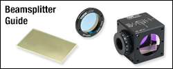
 Products Home / Polarization Optics / Polarizers / Polarizing Beamsplitters / Polarizing Beamsplitting Cubes / Wire Grid Polarizing Beamsplitter Cube
Wire Grid Polarizing Beamsplitter Cube
- Polarize and Split Wavelengths from 400 to 700 nm
- Accepts Broad Angles of Incidence and Uncollimated Light
- High Extinction Ratio: >1 000:1 for Transmitted Beam
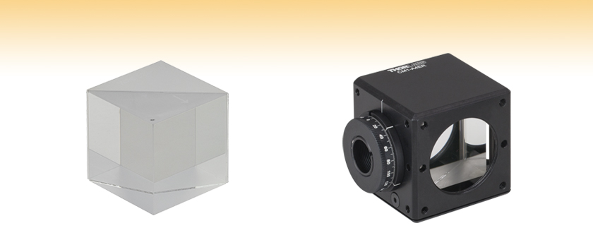
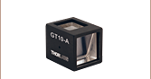
WPBS254-VIS
1" Wire Grid Polarizing
Beamsplitter Cube
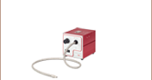
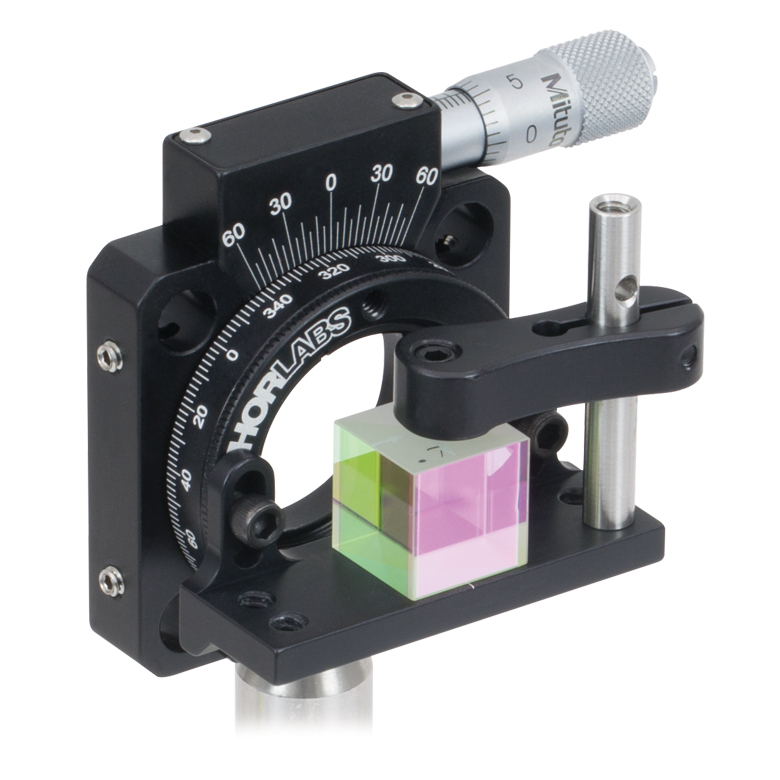
Application Idea
WPBS254-VIS Cube Mounted in a
CM1-A4ER 30 mm Cage Cube


Please Wait
Figure 1.2 Transmission and Reflection of Light Through Wire Grid Polarizing Beamsplitter
Figure 1.1 Wire Grid Beamsplitter Diagram (Not to Scale)
Features
- Transmits P-Polarized Light and Reflects S-Polarized Light
- Unmounted 1" Polarizing Beamsplitter Cube
- Large Field of View
- High Extinction Ratio
- Tp:Ts > 1 000:1 (AOI: 0° - 5°)
- Tp:Ts > 100:1 (AOI: 0° - 25°)
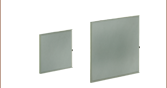
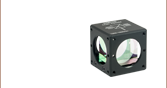
Thorlabs' Wire Grid Polarizing Beamsplitter Cube consists of an array of parallel metallic wires sandwiched between two N-BK7 prisms. Wire grid polarizers transmit radiation with an electric field vector perpendicular to the wire and reflect radiation with the electric field vector parallel to the wire. This cube separates the s- and p-polarized components by reflecting the s-polarized component at the wire grid, while allowing the p-polarized component to pass. Due to surface reflections, the reflected beam contains both polarizations.
This type of beamsplitter cube has a larger Angle of Incidence (AOI) than traditional broadband polarizing beamsplitter cubes. For the highest polarization extinction ratio, use the transmitted beam, which offers an extinction ratio of Tp:Ts > 1 000:1 for an AOI from 0° to 5°. For higher AOI (5° to 25°), this cube can maintain an extinction ratio of Tp:Ts > 100:1.
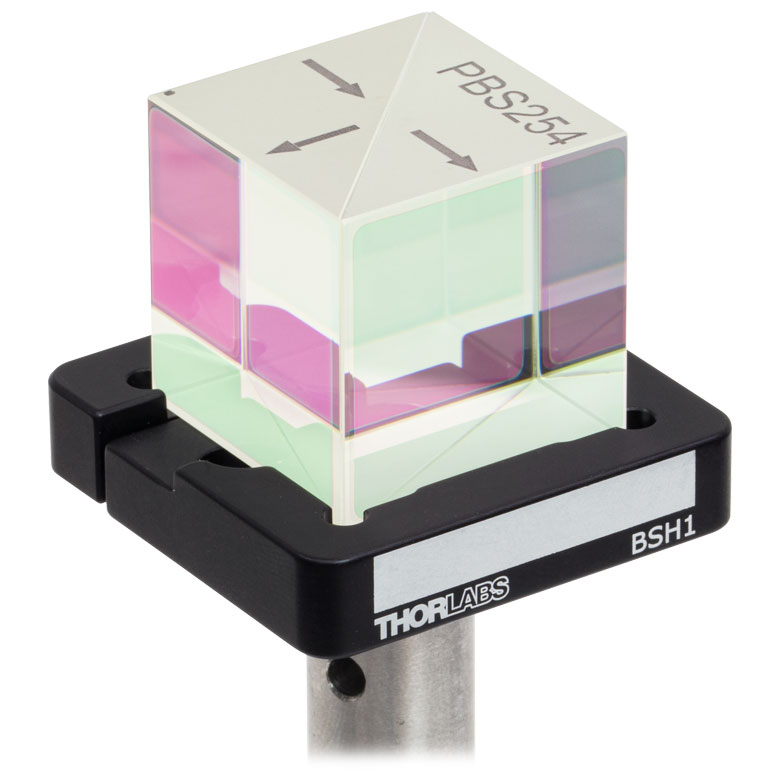
The wire grid is sandwiched between the hypotenuses of the two prisms that make up the cube. Then, optical cement is used to bind the two prism halves together (refer to Figure 1.1). The engraved dot on the top of the cube indicates the prism with the wire grid polarizer. Light can be input into any of the polished faces to separate the s- and p-polarizations. One possible orientation is engraved on the top of the cube. Please refer to the BS Cube Mounting tab for information on mounting options and compatibility.
This beamsplitter cube is AR coated for 400 - 700 nm (Ravg < 0.5% @ 0° AOI). Custom beamsplitter cubes can be ordered by contacting Tech Support. For high power applications, we also offer high-power polarizing beamsplitting cubes that have damage thresholds greater than 10 J/cm2. Mounted wire grid beamsplitting cubes are available. We also offer polarizing beamsplitter cubes at laser line wavelengths, which have a high extinction ratio of >3 000:1 (Tp:Ts).
| Item # | WPBS254-VIS |
|---|---|
| Design Wavelength | 400 - 700 nm |
| AR Coating | Ravg < 0.5% @ 0° AOI for 400 - 700 nm |
| Material | N-BK7 |
| Extinction Ratioa | Tp:Ts > 1 000:1 @ 0° - 5° AOI Tp:Ts > 100:1 @ 0° - 25° AOI |
| Transmission | Tp > 75% (Avg.) @ 0° AOI for 400 - 700 nm |
| Reflectance | Rs > 70% @ 0° - 25° AOI for 400 - 700 nm |
| Transmitted Beam Deviation | <5 arcmin |
| Reflected Beam Deviation | 90° ± 5 arcmin |
| Clear Apertureb | >22.9 mm x 22.9 mm |
| Transmitted Wavefront Error | <λ/4 @ 633 nm |
| Surface Quality | 40-20 Scratch-Dig (Four Side Faces) 80-50 Scratch-Dig (Hypotenuse) |
| Dimensions (L = W = H) | 1" (25.4 mm) |
| Dimensional Tolerance | +0.00 mm / -0.25 mm |
Click to Enlarge
Click for Raw Data
This graph shows the measured extinction ratio (ER) for transmitted light for light incident upon one of the entrance faces. The extinction ratio (also known as contrast) is the ratio of the maximum transmission of a sufficiently linearly polarized signal when the polarizer’s axis is aligned with the signal to the minimum transmission when the polarizer is rotated by 90°. The plotted data is given for AOIs of 0° and ±25°.
Click to Enlarge
Click for Raw Data
This graph shows the measured transmission through the wire grid polarizing cube for p-polarized light for light incident upon one of the entrance faces. The plotted data is given for AOIs of 0° and ±25°.
Click to Enlarge
Click for Raw Data
This graph shows the measured transmission through the wire grid polarizing cube for s-polarized light for light incident upon one of the entrance faces. The plotted data is given for AOIs of 0° and ±25°.
Click to Enlarge
Click for Raw Data
This graph shows the measured reflectance from the wire grid polarizing cube for p-polarized light for light incident upon one of the entrance faces. The plotted data is given for AOIs of 0° and ±25°.
Click to Enlarge
Click for Raw Data
This graph shows the measured reflectance from the wire grid polarizing cube for s-polarized light for light incident upon one of the entrance faces. The plotted data is given for AOIs of 0° and ±25°.
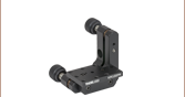
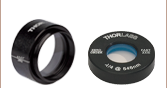
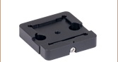
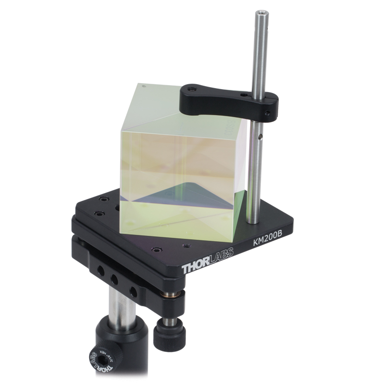
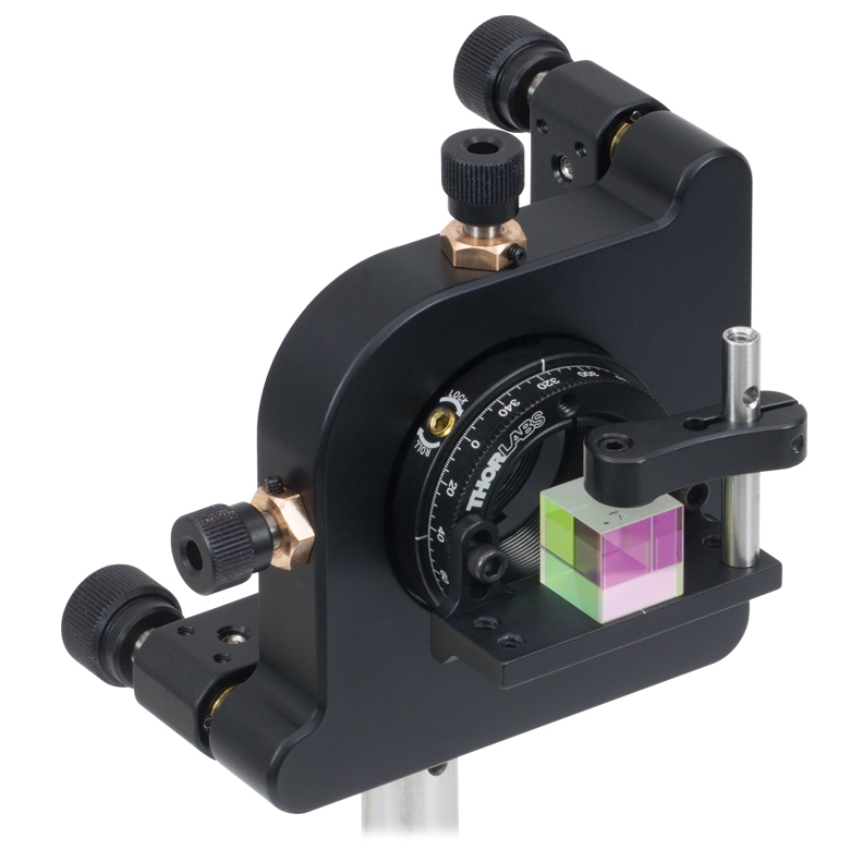
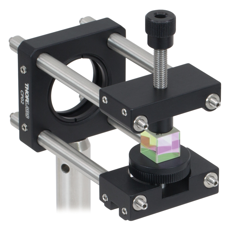
Thorlabs offers a variety of mounting solutions for our beamsplitter cubes. The mounts listed here allow our cubes to be post-mounted or integrated into our 16 mm or 30 mm cage systems. Post-mountable solutions are compatible with our Ø1/2" Posts as well as Ø1" Posts with 8-32 (M4) taps.
| Post-Mountable Mounts for Beamsplitter Cubes | ||||||||
|---|---|---|---|---|---|---|---|---|
| Click Photo to Enlarge (Cubes Not Included) |
 |
 |
 |
 |
 |
 |
 |
 |
| Item # | PCM(/M) | BSH10(/M) BSH05(/M) BSH20(/M) BSH1(/M) BSH2(/M) |
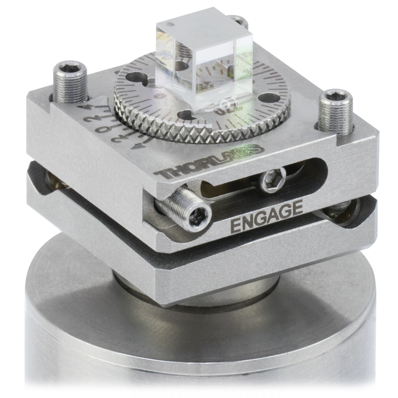
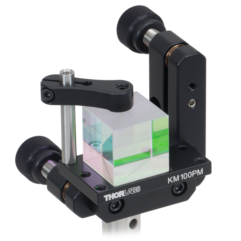
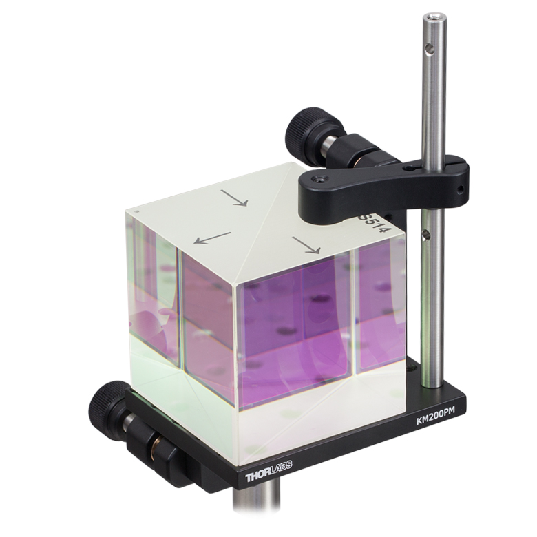
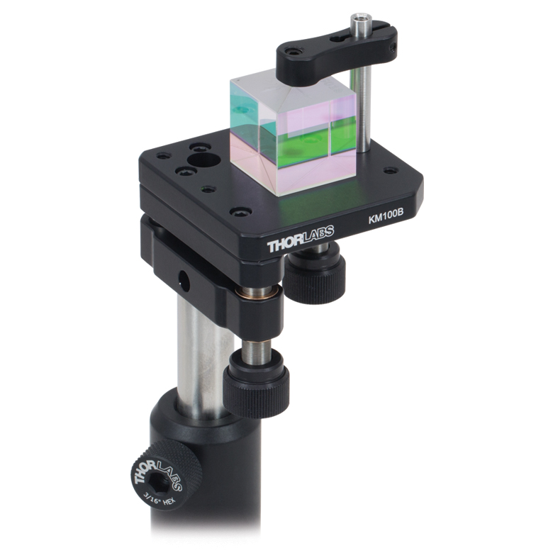
FBTB(/M) | KM100PM(/M) | KM200PM(/M) | KM100B(/M) | KM200B(/M) | K6XS |
| Required Accessories | Base: PCMP(/M) | - | - | Clamp: PM3(/M) or PM4(/M) |
Clamp: PM3(/M) or PM4(/M) |
Clamp: PM3(/M) or PM4(/M) |
Clamp: PM3(/M) or PM4(/M) |
Adapter: K6A1(/M) |
| Mounting Options | Ø1/2" Posts | Ø1/2" Postsa,b | Ø1/2" Posts | Ø1/2" Posts | Ø1/2" Posts | Ø1/2" Posts | Ø1/2" Posts | Ø1/2" Posts |
| Features | Compact | Compact | Glue-In Mount with Precision Tip, Tilt, and Rotation | Tip and Rotation | Tip and Rotation | Kinematic Mount | Kinematic Mount | 6-Axis Mount |
| Compatible Beamsplitter Cube Size(s) |
Up to 20 mm | 10 mm, 1/2", 20 mm, 1", 2" |
5 mm | Up to 20 mmc Up to 1" d |
Up to 20 mmc Up to 1" d Up to 2" e |
Up to 20 mmc Up to 1" d |
Up to 20 mmc Up to 1" d Up to 2" e |
5 mm 10 mm 1/2" |
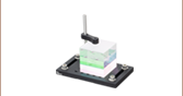
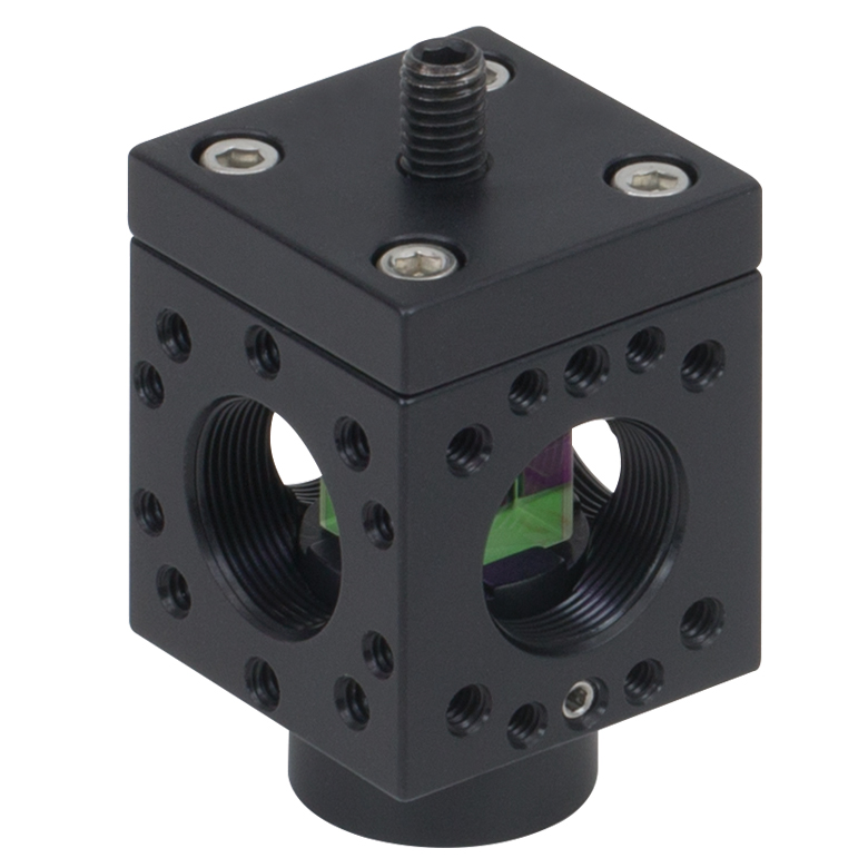
| Cage System Mounts for Beamsplitter Cubes | |||||||||
|---|---|---|---|---|---|---|---|---|---|
| Click Photo to Enlarge (Cubes Not Included) |
 |
 |
 |
 |
 |
 |
 |
 |
 |
| Item # | Cage Cube: SC6W |
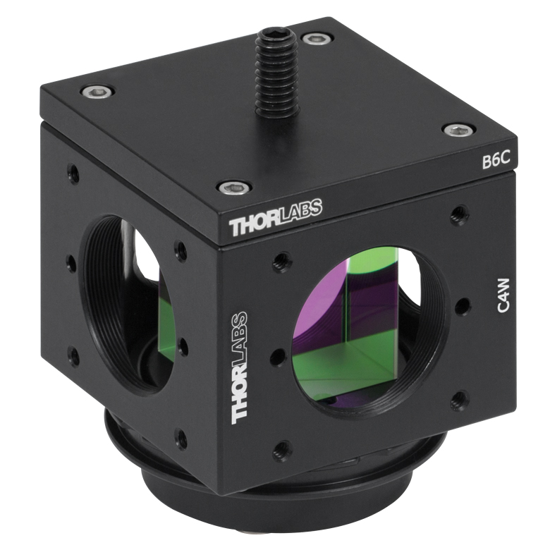
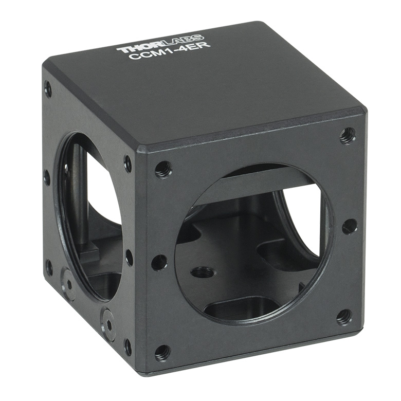
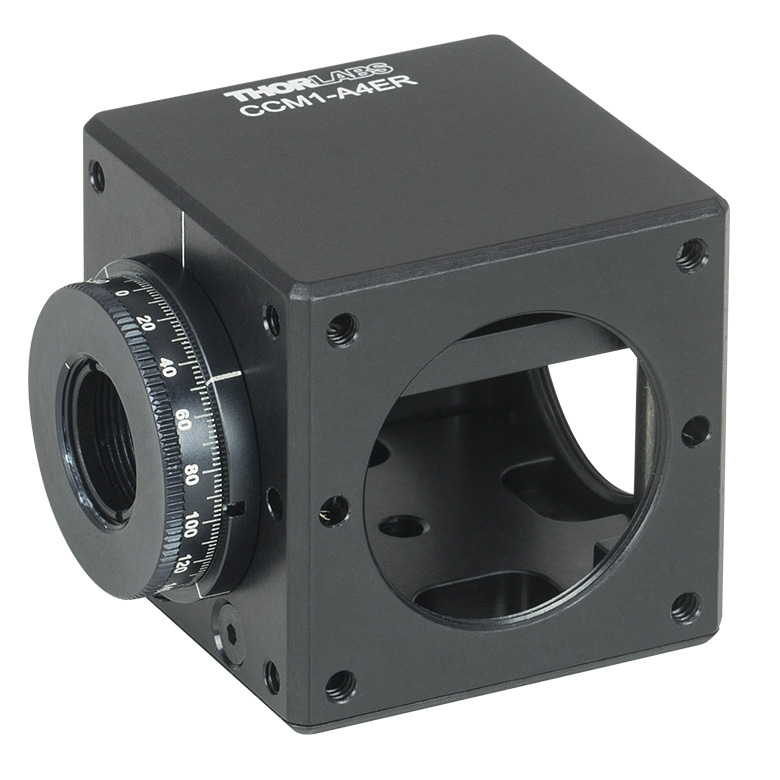
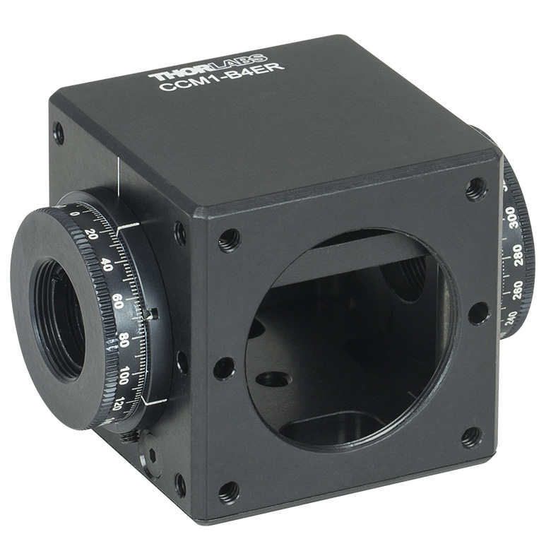
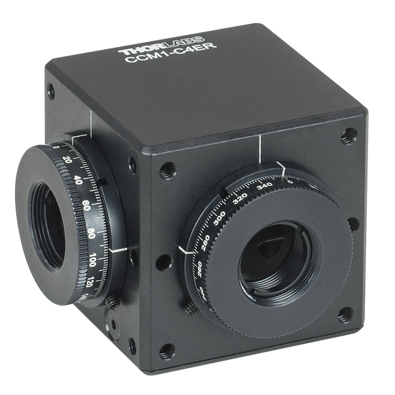
ARV1 | CRM1(/M) or CRM1P(/M) | Cage Cube: C4W or C6W a | CCM1-4ER(/M) | CCM1-A4ER(/M) | CCM1-B4ER(/M) | CCM1-C4ER(/M) | |
| Required Accessories | Clamp: SB6C, Platform: SPM2 |
- | Adapter: K6A1(/M) |
Clamp: B6C, Platform: B3C(/M) or B4C(/M) |
Clamp: B6C, Platform: B3CR(/M) or B4CRP(/M) |
- | - | - | - |
| Mounting Options |
16 mm Cage Systems | 30 mm Cage Systems | 30 mm Cage Systems or Ø1/2" Posts | 30 mm Cage Systems | 30 mm Cage Systems or Ø1/2" Posts | ||||
| Features | Compact | Compact | Rotation Mount | Fixed or Kinematic Platforms | Rotation Platforms | - | One Rotation Mount | Two Rotation Mounts @ 180° | Two Rotation Mounts @ 90° |
| Compatible Beamsplitter Cube Size(s) |
10 mm | 5 mm 10 mm |
5 mm 10 mm 1/2" |
1/2" 20 mm 1" |
5 mm (with BS5CAM Adapter) 10 mm (with BS10CAM Adapter) 1/2" (with BS127CAM Adapter) 20 mm (with BS20CAM Adapter) 1" (Directly Compatible) |
||||
| Posted Comments: | |
Marieke Ordway
(posted 2024-09-16 16:51:12.107) Hello,
Do you have performance data below 400 nm?
Thank you blarowe
(posted 2024-10-07 09:25:38.0) Thank you for reaching out to us. Unfortunately, we don't currently have this data available. I have reached out to you directly to discuss your application and possible alternatives. Additional data and specifications can be requested by reaching out to us at techsupport@thorlabs.com khaled.sarayeddine
(posted 2017-09-26 08:36:23.62) Hi,
Could you please let me know what is the Reflected wavefront aberration for the Wire grid PBS reference: WPBS254-VIS.
YOu only discolse the transmitted wavefront aberration, but not the reflection one.
I would like to check if I can use the polarizer to reflect an image with 60lp/mm!
Regards nbayconich
(posted 2019-01-02 04:18:24.0) Thank you for contacting Thorlabs. The Reflected wavefront error will be typically higher than the transmitted wavefront error for these beamsplitters. I will reach out to you directly about your application. user
(posted 2014-10-16 10:39:55.653) "For high power applications, we also offer high power polarizing beamsplitting cubes. " What power do you define HIGH POWER? myanakas
(posted 2014-10-20 11:22:53.0) Response from Mike at Thorlabs: Thank you for your feedback. Our high-power polarizing beamsplitters, which can be found here http://www.thorlabs.com/newgrouppage9.cfm?objectgroup_id=6055&tabname=Damage Thresholds, have damage thresholds greater than 10 J/cm^2. For more information on the damage thresholds for our high-power polarizing beamsplitters, please click the link above. |
Polarizer Selection Guide
Thorlabs offers a diverse range of polarizers, including wire grid, film, calcite, alpha-BBO, rutile, and beamsplitting polarizers. Collectively, our line of wire grid polarizers offers coverage from the visible range to the beginning of the Far-IR range. Our nanoparticle linear film polarizers provide extinction ratios as high as 100 000:1. Alternatively, our other film polarizers offer an affordable solution for polarizing light from the visible to the Near-IR. Next, our beamsplitting polarizers allow for use of the reflected beam, as well as the more completely polarized transmitted beam. Finally, our alpha-BBO (UV), calcite (visible to Near-IR), rutile (Near-IR to Mid-IR), and yttrium orthovanadate (YVO4) (Near-IR to Mid-IR) polarizers each offer an exceptional extinction ratio of 100 000:1 within their respective wavelength ranges.
To explore the available types, wavelength ranges, extinction ratios, transmission, and available sizes for each polarizer category, click More [+] in the appropriate row below.
| Wire Grid Polarizers |
|---|
| Film Polarizers |
|---|


| Beamsplitting Polarizers |
|---|


| alpha-BBO Polarizers |
|---|
| Calcite Polarizers |
|---|
| Quartz Polarizers |
|---|
| Magnesium Fluoride Polarizers |
|---|
| Yttrium Orthovanadate (YVO4) Polarizers |
|---|
| Rutile Polarizers |
|---|
Beamsplitter Selection Guide
Thorlabs' portfolio contains many different kinds of beamsplitters, which can split beams by intensity or by polarization. We offer plate and cube beamsplitters, though other form factors exist, including pellicle and birefringent crystal. For an overview of the different types and a comparison of their features and applications, please see our overview. Many of our beamsplitters come in premounted or unmounted variants. In this tab is a complete listing of our beamsplitter offerings. To explore the available types, wavelength ranges, splitting/extinction ratios, transmission, and available sizes for each beamsplitter category, click More [+] in the appropriate row.Plate Beamsplitters
| Non-Polarizing Plate Beamsplitters |
|---|


| Polarizing Plate Beamsplitters |
|---|
Cube Beamsplitters
| Non-Polarizing Cube Beamsplitters |
|---|


| Polarizing Cube and Polyhedron Beamsplitters |
|---|


Pellicle Beamsplitters
| Non-Polarizing Pellicle Beamsplitters |
|---|


Crystal Beamsplitters
| Polarizing Crystal Beamsplitters |
|---|
Other
| Other Beamsplitters |
|---|