 Products Home / Optical Elements / Optical Beamsplitters / Beamsplitter Cubes / Non-Polarizing Beamsplitter Cubes / Non-Polarizing Cube Beamsplitters (700 - 1100 nm)
Non-Polarizing Cube Beamsplitters (700 - 1100 nm)
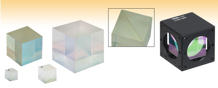
- Beamsplitter Coating for 700 - 1100 nm
- 10:90, 30:70, 50:50, 70:30, or 90:10 (R:T) Split Ratio
- AR Coating on Both Input and Output Faces
BS008
5 mm
BS005
1/2"
BS020
1"
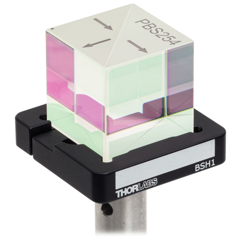
Engravings Mark the Directions
of Light Propagation
BS032
2"
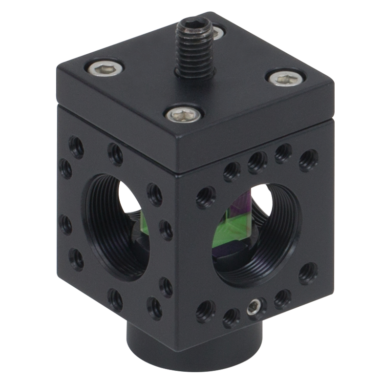
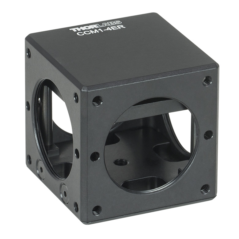
1" Beamsplitter Cube Shown in CCM1-4ER Prism Cage Cube


Please Wait
| General Specifications | ||
|---|---|---|
| Wavelength Range | 700 - 1100 nm | |
| AR Coating (All Four Surfaces, Click for Plot) |
Ravg < 0.5% at 0° AOI from 700 - 1100 nm |
|
| Substrate Material | N-BK7a | |
| Dimensional Tolerance | +0.0 / -0.2 mm | |
| Reflected Beam Deviation | 90° ± 5 arcmin | |
| Surface Quality | 40-20 Scratch-Dig | |
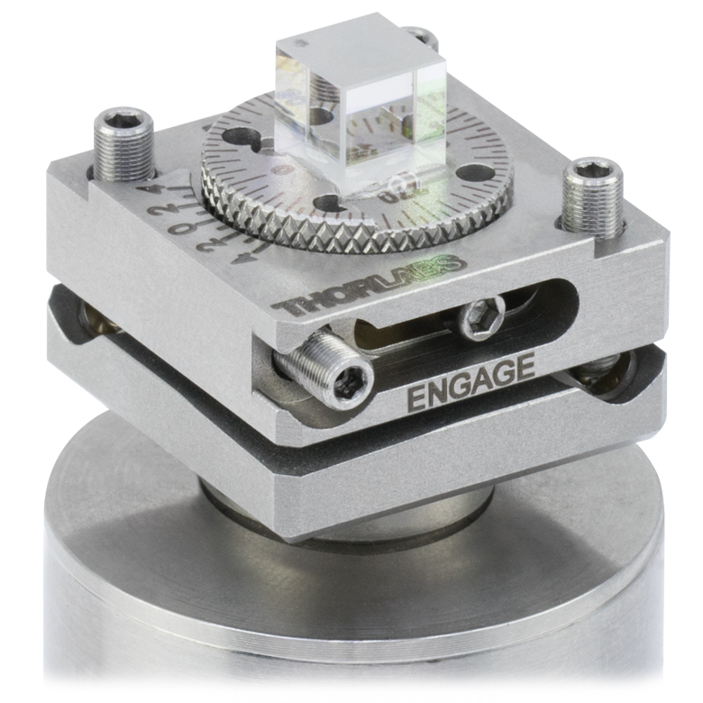
Click to Enlarge
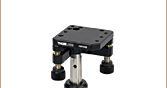
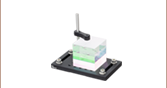
5 mm Beamsplitter Cube Mounted in the FBTB Compact Kinematic Mount on a Ø1" Post with a Post Spacer
(Refer to the BS Cube Mounting Tab for Other Options)
Cube Beamsplitter Diagram (Coating and Cement Layer Not to Scale)
Features
- Broadband AR-Coated Faces for 700 - 1100 nm
- Broadband Beamsplitter Coating on Internal Diagonal Surface
- 10:90, 30:70, 50:50, 70:30, or 90:10 (R:T) Split Ratio
- Sizes from 5 mm to 2" (See Below for Details)
- N-BK7 Substrate
Thorlabs' non-polarizing beamsplitter cubes are offered here with broadband AR and beamsplitter coatings designed for 700 - 1100 nm. These cubes provide a 10:90, 30:70, 50:50, 70:30, or 90:10 beamsplitting ratio with a minimal dependence on the polarization of the incident light (see the tables below for the polarization split ratio tolerances).
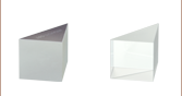
Each cube is fabricated from N-BK7 and designed for minimal beam offset. A single reflecting surface also avoids ghost images. The dielectric beamsplitter coating is applied to the hypotenuse of one of the two prisms that make up the cube. Then, cement is used to bind the two prism halves together. These cubes are engraved with arrows that indicate the direction in which the beam is incident on the beamsplitter coating layer, as shown in the diagram to the right. Although light can enter through any of the other AR-coated surfaces, specifications are guaranteed when light is first incident on the side of the beamsplitter coating; see the diagram to the right.
Please refer to the BS Cube Mounting tab above for information on mounting options and compatibility. Alternatively, we offer mounted 1" non-polarizing beamsplitter cubes and 20 mm non-polarizing beamsplitter cubes. The 1" cubes are mounted inside 30 mm cage compatible cubes, each of which features four SM1-threaded (1.035"-40) access ports, while the 20 mm cubes are mounted within 16 mm cage compatible cubes, each of which features four SM05-threaded (0.535"-40) access ports. Additionally, Thorlabs offers pellicle beamsplitters (cube mounted and ring mounted) and plate beamsplitters. For a direct comparison of the performance of our non-polarizing beamsplitter cube, plate, and pellicle at 633 nm, see the Lab Facts tab.

| Non-Polarizing Cube Beamsplitters |
|---|
| Visible (400 - 700 nm) Beamsplitters |
| NIR (700 - 1100 nm) Beamsplitters |
| IR (1100 - 1600 nm) Beamsplitters |
| Mounted Cube Beamsplitters |
| General Specifications | ||
|---|---|---|
| Wavelength Range | 700 - 1100 nm | |
| AR Coating (All Four Surfaces, Click for Plot) | Ravg < 0.5% at 0° AOI from 700 - 1100 nm | |
| Substrate Material | N-BK7a | |
| Dimensional Tolerance | +0.0/-0.2 mm | |
| Reflected Beam Deviation | 90° ± 5 arcmin | |
| Surface Quality | 40-20 Scratch-Dig | |
| Item # | Size | Surface Flatness (@ 633 nm) |
Transmitted Wavefront Error (@ 633 nm) |
Transmitted Beam Deviation |
Overall Performanceb |
|---|---|---|---|---|---|
| 10:90 (R:T) Split Ratio | |||||
| BS035a | 5 mm Cube | - | <λ/4 | 0° ± 5 arcmin | Tabs = 87 ± 10%, Rabs = 7 +10/-7%, and Tabs + Rabs > 85% |Ts - Tp| < 10% and |Rs - Rp| < 10% |
| BS038 | 10 mm Cube | ||||
| BS041 | 1/2" (12.7 mm) Cube | Tabs = 87 ± 10%, Rabs = 7 +10/-5%, and Tabs + Rabs > 85% |Ts - Tp| < 10% and |Rs - Rp| < 10% |
|||
| BS044 | 20 mm Cube | Tabs = 87 ± 10%, Rabs = 7 +10/-7%, and Tabs + Rabs > 85% |Ts - Tp| < 10% and |Rs - Rp| < 10% |
|||
| BS026 | 1" (25.4 mm) Cube | Tabs = 87 ± 10%, Rabs = 7 +10/-5%, and Tabs + Rabs > 85% |Ts - Tp| < 10% and |Rs - Rp| < 10% |
|||
| 30:70 (R:T) Split Ratio | |||||
| BS047a | 5 mm Cube | - | <λ/4 | 0° ± 5 arcmin | Tabs = 62 ± 10%, Rabs = 27 ± 10%, and Tabs + Rabs > 80% |Ts - Tp| < 10% and |Rs - Rp| < 10% |
| BS050 | 10 mm Cube | ||||
| BS053 | 1/2" (12.7 mm) Cube | ||||
| BS080 | 20 mm Cube | ||||
| BS020 | 1" (25.4 mm) Cube | ||||
| 50:50 (R:T) Split Ratio | |||||
| BS008a | 5 mm Cube | - | <λ/4 | 0° ± 5 arcmin | Tabs = 47 ± 10%, Rabs = 47 ± 10%, and Tabs + Rabs > 90% |Ts - Tp| < 10% and |Rs - Rp| < 10% |
| BS011 | 10 mm Cube | ||||
| BS005 | 1/2" (12.7 mm) Cube | ||||
| BS017 | 20 mm Cube | ||||
| BS014 | 1" (25.4 mm) Cube | ||||
| BS032 | 2" (50.8 mm) Cube | <λ | Tabs= 47 ± 10%, Rabs= 47 ± 10% Tabs + Rabs > 85% Tavg + Ravg > 90% |Ts - Tp| < 10% and |Rs - Rp| < 10% |
||
| 70:30 (R:T) Split Ratio | |||||
| BS056 | 5 mm Cube | - | <λ/4 | 0° ± 5 arcmin | Tabs = 27 ± 10%, Rabs = 67 +5/-15%, and Tabs + Rabs > 85% |Ts - Tp| < 10% and |Rs - Rp| < 10% |
| BS059 | 10 mm Cube | ||||
| BS062 | 1/2" (12.7 mm) Cube | ||||
| BS065 | 20 mm Cube | ||||
| BS023 | 1" (25.4 mm) Cube | <λ/10 | <5 arcmin | ||
| 90:10 (R:T) Split Ratio | |||||
| BS068 | 5 mm Cube | - | <λ/4 | 0° ± 5 arcmin | Tabs = 7 +10/-5%, Rabs = 87 ± 10%, and Tabs + Rabs > 85% |Ts - Tp| < 10% and |Rs - Rp| < 10% |
| BS071 | 10 mm Cube | ||||
| BS074 | 1/2" (12.7 mm) Cube | ||||
| BS077 | 20 mm Cube | ||||
| BS029 | 1" (25.4 mm) Cube | ||||
Thorlabs Lab Fact: Beamsplitter Package Matters
We present laboratory measurements of the polarization angle, split ratio, and total throughput power of a beam transmitted through Thorlabs plate, cube, and pellicle beamsplitters. While all non-polarizing beamsplitters function similarly, the exact performance is different for different types of beamsplitter. Each type of beamsplitter contains its own advantages and disadvantages compared to other types of beamsplitters. Appropriate choice of beamsplitter is essential to sensitive experimental systems. We present a complete analysis and comparison of optical parameters for three common types of non-polarizing beamsplitters.
For our experiment we used the former generation HRS015 stabilized HeNe laser (replaced by the HRS015B) as the light source for our investigation. A linear polarizer is used to set the laser beam's polarization axis to 45° in order to provide equal s- and p-polarized light incident on the beamsplitter. The beamsplitter under investigation was then placed in the beampath, and its split beams directed to appropriate detectors. The total power though the optic, polarization states, split ratios, and angle of incidence effects were investigated under this configuration.

The plots below summarize the measured results for all three types of beamsplitters. From these graphs the performance of each optic can be easily compared to one another. The bottom left plot summarizes the results for the total power throughput for each optic. The total power throughput is measured as the fraction of input power. While the plate and pellicle beamsplitters perform rather similarly, the cube shows signs of absorption inside the optic. Additionally, this plot shows the relative insensitivity of throughput power to angle of incidence. The bottom middle graph summarizes the results for the output polarization angle for each optic. The cube shows the most similar polarization angles between the reflected and transmitted beams, with the plate producing the largest difference in polarization between beams. The bottom right plot summarizes the results for the split ratio, as a fraction of input power, for the beamsplitters. Here it can be shown that the plate beamsplitter demonstrates the most ideal for 50/50 power splitting. For details on the experimental setup employed and the results summarized here, please click here.
| Damage Threshold Specificationsa | ||
|---|---|---|
| Split Ratio | Laser Type | Damage Threshold |
| 50:50 | Pulse | 0.25 J/cm2 (810 nm, 10 ns, 10 Hz, Ø0.166 mm) |
| CWb | 10 W/cm (1070 nm, Ø1.012 mm) | |
Damage Threshold Data for Thorlabs' 50:50 (R:T) Non-Polarizing Cube Beamsplitters
The specifications to the right are measured data for Thorlabs' non-polarizing cube beamsplitters with wavelength range from 700 to 1100 nm. Damage threshold specifications are constant for all coatings, regardless of the size of the beamsplitter.
Laser Induced Damage Threshold Tutorial
The following is a general overview of how laser induced damage thresholds are measured and how the values may be utilized in determining the appropriateness of an optic for a given application. When choosing optics, it is important to understand the Laser Induced Damage Threshold (LIDT) of the optics being used. The LIDT for an optic greatly depends on the type of laser you are using. Continuous wave (CW) lasers typically cause damage from thermal effects (absorption either in the coating or in the substrate). Pulsed lasers, on the other hand, often strip electrons from the lattice structure of an optic before causing thermal damage. Note that the guideline presented here assumes room temperature operation and optics in new condition (i.e., within scratch-dig spec, surface free of contamination, etc.). Because dust or other particles on the surface of an optic can cause damage at lower thresholds, we recommend keeping surfaces clean and free of debris. For more information on cleaning optics, please see our Optics Cleaning tutorial.
Testing Method
Thorlabs' LIDT testing is done in compliance with ISO/DIS 11254 and ISO 21254 specifications.
First, a low-power/energy beam is directed to the optic under test. The optic is exposed in 10 locations to this laser beam for 30 seconds (CW) or for a number of pulses (pulse repetition frequency specified). After exposure, the optic is examined by a microscope (~100X magnification) for any visible damage. The number of locations that are damaged at a particular power/energy level is recorded. Next, the power/energy is either increased or decreased and the optic is exposed at 10 new locations. This process is repeated until damage is observed. The damage threshold is then assigned to be the highest power/energy that the optic can withstand without causing damage. A histogram such as that below represents the testing of one BB1-E02 mirror.

The photograph above is a protected aluminum-coated mirror after LIDT testing. In this particular test, it handled 0.43 J/cm2 (1064 nm, 10 ns pulse, 10 Hz, Ø1.000 mm) before damage.

| Example Test Data | |||
|---|---|---|---|
| Fluence | # of Tested Locations | Locations with Damage | Locations Without Damage |
| 1.50 J/cm2 | 10 | 0 | 10 |
| 1.75 J/cm2 | 10 | 0 | 10 |
| 2.00 J/cm2 | 10 | 0 | 10 |
| 2.25 J/cm2 | 10 | 1 | 9 |
| 3.00 J/cm2 | 10 | 1 | 9 |
| 5.00 J/cm2 | 10 | 9 | 1 |
According to the test, the damage threshold of the mirror was 2.00 J/cm2 (532 nm, 10 ns pulse, 10 Hz, Ø0.803 mm). Please keep in mind that these tests are performed on clean optics, as dirt and contamination can significantly lower the damage threshold of a component. While the test results are only representative of one coating run, Thorlabs specifies damage threshold values that account for coating variances.
Continuous Wave and Long-Pulse Lasers
When an optic is damaged by a continuous wave (CW) laser, it is usually due to the melting of the surface as a result of absorbing the laser's energy or damage to the optical coating (antireflection) [1]. Pulsed lasers with pulse lengths longer than 1 µs can be treated as CW lasers for LIDT discussions.
When pulse lengths are between 1 ns and 1 µs, laser-induced damage can occur either because of absorption or a dielectric breakdown (therefore, a user must check both CW and pulsed LIDT). Absorption is either due to an intrinsic property of the optic or due to surface irregularities; thus LIDT values are only valid for optics meeting or exceeding the surface quality specifications given by a manufacturer. While many optics can handle high power CW lasers, cemented (e.g., achromatic doublets) or highly absorptive (e.g., ND filters) optics tend to have lower CW damage thresholds. These lower thresholds are due to absorption or scattering in the cement or metal coating.

LIDT in linear power density vs. pulse length and spot size. For long pulses to CW, linear power density becomes a constant with spot size. This graph was obtained from [1].

Pulsed lasers with high pulse repetition frequencies (PRF) may behave similarly to CW beams. Unfortunately, this is highly dependent on factors such as absorption and thermal diffusivity, so there is no reliable method for determining when a high PRF laser will damage an optic due to thermal effects. For beams with a high PRF both the average and peak powers must be compared to the equivalent CW power. Additionally, for highly transparent materials, there is little to no drop in the LIDT with increasing PRF.
In order to use the specified CW damage threshold of an optic, it is necessary to know the following:
- Wavelength of your laser
- Beam diameter of your beam (1/e2)
- Approximate intensity profile of your beam (e.g., Gaussian)
- Linear power density of your beam (total power divided by 1/e2 beam diameter)
Thorlabs expresses LIDT for CW lasers as a linear power density measured in W/cm. In this regime, the LIDT given as a linear power density can be applied to any beam diameter; one does not need to compute an adjusted LIDT to adjust for changes in spot size, as demonstrated by the graph to the right. Average linear power density can be calculated using the equation below.

The calculation above assumes a uniform beam intensity profile. You must now consider hotspots in the beam or other non-uniform intensity profiles and roughly calculate a maximum power density. For reference, a Gaussian beam typically has a maximum power density that is twice that of the uniform beam (see lower right).
Now compare the maximum power density to that which is specified as the LIDT for the optic. If the optic was tested at a wavelength other than your operating wavelength, the damage threshold must be scaled appropriately. A good rule of thumb is that the damage threshold has a linear relationship with wavelength such that as you move to shorter wavelengths, the damage threshold decreases (i.e., a LIDT of 10 W/cm at 1310 nm scales to 5 W/cm at 655 nm):

While this rule of thumb provides a general trend, it is not a quantitative analysis of LIDT vs wavelength. In CW applications, for instance, damage scales more strongly with absorption in the coating and substrate, which does not necessarily scale well with wavelength. While the above procedure provides a good rule of thumb for LIDT values, please contact Tech Support if your wavelength is different from the specified LIDT wavelength. If your power density is less than the adjusted LIDT of the optic, then the optic should work for your application.
Please note that we have a buffer built in between the specified damage thresholds online and the tests which we have done, which accommodates variation between batches. Upon request, we can provide individual test information and a testing certificate. The damage analysis will be carried out on a similar optic (customer's optic will not be damaged). Testing may result in additional costs or lead times. Contact Tech Support for more information.
Pulsed Lasers
As previously stated, pulsed lasers typically induce a different type of damage to the optic than CW lasers. Pulsed lasers often do not heat the optic enough to damage it; instead, pulsed lasers produce strong electric fields capable of inducing dielectric breakdown in the material. Unfortunately, it can be very difficult to compare the LIDT specification of an optic to your laser. There are multiple regimes in which a pulsed laser can damage an optic and this is based on the laser's pulse length. The highlighted columns in the table below outline the relevant pulse lengths for our specified LIDT values.
Pulses shorter than 10-9 s cannot be compared to our specified LIDT values with much reliability. In this ultra-short-pulse regime various mechanics, such as multiphoton-avalanche ionization, take over as the predominate damage mechanism [2]. In contrast, pulses between 10-7 s and 10-4 s may cause damage to an optic either because of dielectric breakdown or thermal effects. This means that both CW and pulsed damage thresholds must be compared to the laser beam to determine whether the optic is suitable for your application.
| Pulse Duration | t < 10-9 s | 10-9 < t < 10-7 s | 10-7 < t < 10-4 s | t > 10-4 s |
|---|---|---|---|---|
| Damage Mechanism | Avalanche Ionization | Dielectric Breakdown | Dielectric Breakdown or Thermal | Thermal |
| Relevant Damage Specification | No Comparison (See Above) | Pulsed | Pulsed and CW | CW |
When comparing an LIDT specified for a pulsed laser to your laser, it is essential to know the following:

LIDT in energy density vs. pulse length and spot size. For short pulses, energy density becomes a constant with spot size. This graph was obtained from [1].
- Wavelength of your laser
- Energy density of your beam (total energy divided by 1/e2 area)
- Pulse length of your laser
- Pulse repetition frequency (prf) of your laser
- Beam diameter of your laser (1/e2 )
- Approximate intensity profile of your beam (e.g., Gaussian)
The energy density of your beam should be calculated in terms of J/cm2. The graph to the right shows why expressing the LIDT as an energy density provides the best metric for short pulse sources. In this regime, the LIDT given as an energy density can be applied to any beam diameter; one does not need to compute an adjusted LIDT to adjust for changes in spot size. This calculation assumes a uniform beam intensity profile. You must now adjust this energy density to account for hotspots or other nonuniform intensity profiles and roughly calculate a maximum energy density. For reference a Gaussian beam typically has a maximum energy density that is twice that of the 1/e2 beam.
Now compare the maximum energy density to that which is specified as the LIDT for the optic. If the optic was tested at a wavelength other than your operating wavelength, the damage threshold must be scaled appropriately [3]. A good rule of thumb is that the damage threshold has an inverse square root relationship with wavelength such that as you move to shorter wavelengths, the damage threshold decreases (i.e., a LIDT of 1 J/cm2 at 1064 nm scales to 0.7 J/cm2 at 532 nm):

You now have a wavelength-adjusted energy density, which you will use in the following step.
Beam diameter is also important to know when comparing damage thresholds. While the LIDT, when expressed in units of J/cm², scales independently of spot size; large beam sizes are more likely to illuminate a larger number of defects which can lead to greater variances in the LIDT [4]. For data presented here, a <1 mm beam size was used to measure the LIDT. For beams sizes greater than 5 mm, the LIDT (J/cm2) will not scale independently of beam diameter due to the larger size beam exposing more defects.
The pulse length must now be compensated for. The longer the pulse duration, the more energy the optic can handle. For pulse widths between 1 - 100 ns, an approximation is as follows:

Use this formula to calculate the Adjusted LIDT for an optic based on your pulse length. If your maximum energy density is less than this adjusted LIDT maximum energy density, then the optic should be suitable for your application. Keep in mind that this calculation is only used for pulses between 10-9 s and 10-7 s. For pulses between 10-7 s and 10-4 s, the CW LIDT must also be checked before deeming the optic appropriate for your application.
Please note that we have a buffer built in between the specified damage thresholds online and the tests which we have done, which accommodates variation between batches. Upon request, we can provide individual test information and a testing certificate. Contact Tech Support for more information.
[1] R. M. Wood, Optics and Laser Tech. 29, 517 (1998).
[2] Roger M. Wood, Laser-Induced Damage of Optical Materials (Institute of Physics Publishing, Philadelphia, PA, 2003).
[3] C. W. Carr et al., Phys. Rev. Lett. 91, 127402 (2003).
[4] N. Bloembergen, Appl. Opt. 12, 661 (1973).

In order to illustrate the process of determining whether a given laser system will damage an optic, a number of example calculations of laser induced damage threshold are given below. For assistance with performing similar calculations, we provide a spreadsheet calculator that can be downloaded by clicking the button to the right. To use the calculator, enter the specified LIDT value of the optic under consideration and the relevant parameters of your laser system in the green boxes. The spreadsheet will then calculate a linear power density for CW and pulsed systems, as well as an energy density value for pulsed systems. These values are used to calculate adjusted, scaled LIDT values for the optics based on accepted scaling laws. This calculator assumes a Gaussian beam profile, so a correction factor must be introduced for other beam shapes (uniform, etc.). The LIDT scaling laws are determined from empirical relationships; their accuracy is not guaranteed. Remember that absorption by optics or coatings can significantly reduce LIDT in some spectral regions. These LIDT values are not valid for ultrashort pulses less than one nanosecond in duration.
A Gaussian beam profile has about twice the maximum intensity of a uniform beam profile.
CW Laser Example
Suppose that a CW laser system at 1319 nm produces a 0.5 W Gaussian beam that has a 1/e2 diameter of 10 mm. A naive calculation of the average linear power density of this beam would yield a value of 0.5 W/cm, given by the total power divided by the beam diameter:
However, the maximum power density of a Gaussian beam is about twice the maximum power density of a uniform beam, as shown in the graph to the right. Therefore, a more accurate determination of the maximum linear power density of the system is 1 W/cm.
An AC127-030-C achromatic doublet lens has a specified CW LIDT of 350 W/cm, as tested at 1550 nm. CW damage threshold values typically scale directly with the wavelength of the laser source, so this yields an adjusted LIDT value:
The adjusted LIDT value of 350 W/cm x (1319 nm / 1550 nm) = 298 W/cm is significantly higher than the calculated maximum linear power density of the laser system, so it would be safe to use this doublet lens for this application.
Pulsed Nanosecond Laser Example: Scaling for Different Pulse Durations
Suppose that a pulsed Nd:YAG laser system is frequency tripled to produce a 10 Hz output, consisting of 2 ns output pulses at 355 nm, each with 1 J of energy, in a Gaussian beam with a 1.9 cm beam diameter (1/e2). The average energy density of each pulse is found by dividing the pulse energy by the beam area:

As described above, the maximum energy density of a Gaussian beam is about twice the average energy density. So, the maximum energy density of this beam is ~0.7 J/cm2.
The energy density of the beam can be compared to the LIDT values of 1 J/cm2 and 3.5 J/cm2 for a BB1-E01 broadband dielectric mirror and an NB1-K08 Nd:YAG laser line mirror, respectively. Both of these LIDT values, while measured at 355 nm, were determined with a 10 ns pulsed laser at 10 Hz. Therefore, an adjustment must be applied for the shorter pulse duration of the system under consideration. As described on the previous tab, LIDT values in the nanosecond pulse regime scale with the square root of the laser pulse duration:
This adjustment factor results in LIDT values of 0.45 J/cm2 for the BB1-E01 broadband mirror and 1.6 J/cm2 for the Nd:YAG laser line mirror, which are to be compared with the 0.7 J/cm2 maximum energy density of the beam. While the broadband mirror would likely be damaged by the laser, the more specialized laser line mirror is appropriate for use with this system.
Pulsed Nanosecond Laser Example: Scaling for Different Wavelengths
Suppose that a pulsed laser system emits 10 ns pulses at 2.5 Hz, each with 100 mJ of energy at 1064 nm in a 16 mm diameter beam (1/e2) that must be attenuated with a neutral density filter. For a Gaussian output, these specifications result in a maximum energy density of 0.1 J/cm2. The damage threshold of an NDUV10A Ø25 mm, OD 1.0, reflective neutral density filter is 0.05 J/cm2 for 10 ns pulses at 355 nm, while the damage threshold of the similar NE10A absorptive filter is 10 J/cm2 for 10 ns pulses at 532 nm. As described on the previous tab, the LIDT value of an optic scales with the square root of the wavelength in the nanosecond pulse regime:
This scaling gives adjusted LIDT values of 0.08 J/cm2 for the reflective filter and 14 J/cm2 for the absorptive filter. In this case, the absorptive filter is the best choice in order to avoid optical damage.
Pulsed Microsecond Laser Example
Consider a laser system that produces 1 µs pulses, each containing 150 µJ of energy at a repetition rate of 50 kHz, resulting in a relatively high duty cycle of 5%. This system falls somewhere between the regimes of CW and pulsed laser induced damage, and could potentially damage an optic by mechanisms associated with either regime. As a result, both CW and pulsed LIDT values must be compared to the properties of the laser system to ensure safe operation.
If this relatively long-pulse laser emits a Gaussian 12.7 mm diameter beam (1/e2) at 980 nm, then the resulting output has a linear power density of 5.9 W/cm and an energy density of 1.2 x 10⁻⁴ J/cm2 per pulse. This can be compared to the LIDT values for a WPQ10E-980 polymer zero-order quarter-wave plate, which are 5 W/cm for CW radiation at 810 nm and 5 J/cm2 for a 10 ns pulse at 810 nm. As before, the CW LIDT of the optic scales linearly with the laser wavelength, resulting in an adjusted CW value of 6 W/cm at 980 nm. On the other hand, the pulsed LIDT scales with the square root of the laser wavelength and the square root of the pulse duration, resulting in an adjusted value of 55 J/cm2 for a 1 µs pulse at 980 nm. The pulsed LIDT of the optic is significantly greater than the energy density of the laser pulse, so individual pulses will not damage the wave plate. However, the large average linear power density of the laser system may cause thermal damage to the optic, much like a high-power CW beam.
Thorlabs offers a variety of mounting solutions for our beamsplitter cubes. The mounts below allow our cubes to be post-mounted or integrated into our 16 mm or 30 mm cage systems. Post-mountable solutions are compatible with our Ø1/2" Posts as well as Ø1" Posts with 8-32 (M4) taps.
| Post-Mountable Mounts for Beamsplitter Cubes | ||||||||
|---|---|---|---|---|---|---|---|---|
| Click Photo to Enlarge (Cubes Not Included) |
 |
 |
|
 |
 |
 |
 |
 |
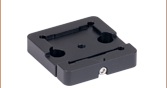
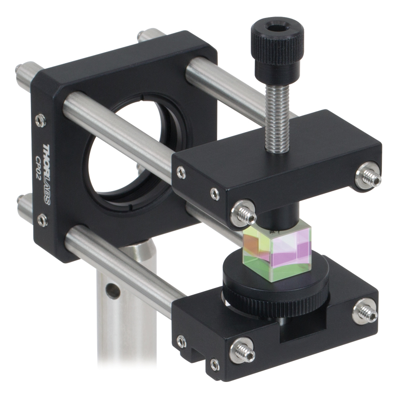
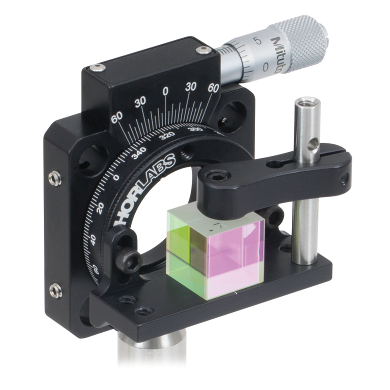
| Item # | PCM(/M) | BSH10(/M) BSH05(/M) BSH20(/M) BSH1(/M) BSH2(/M) |
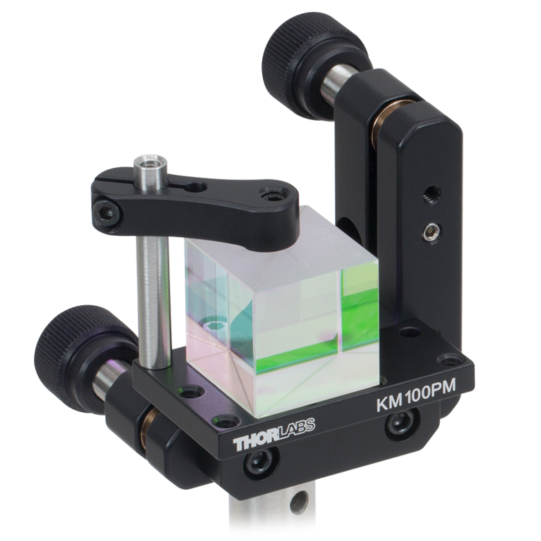
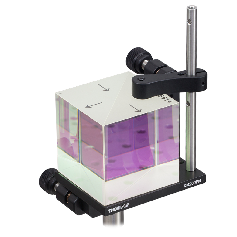
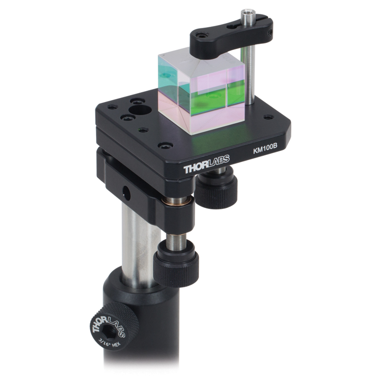
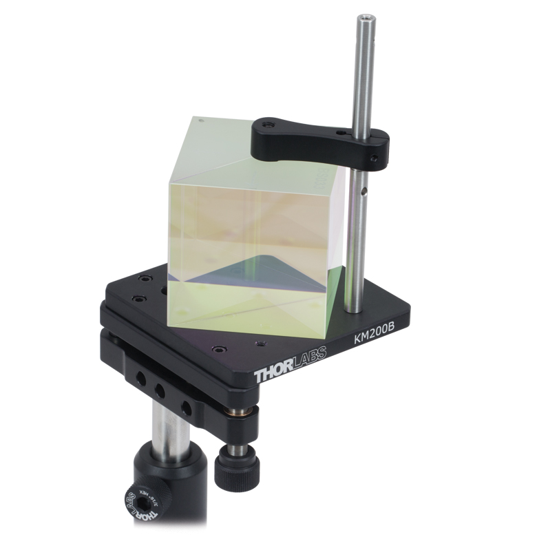
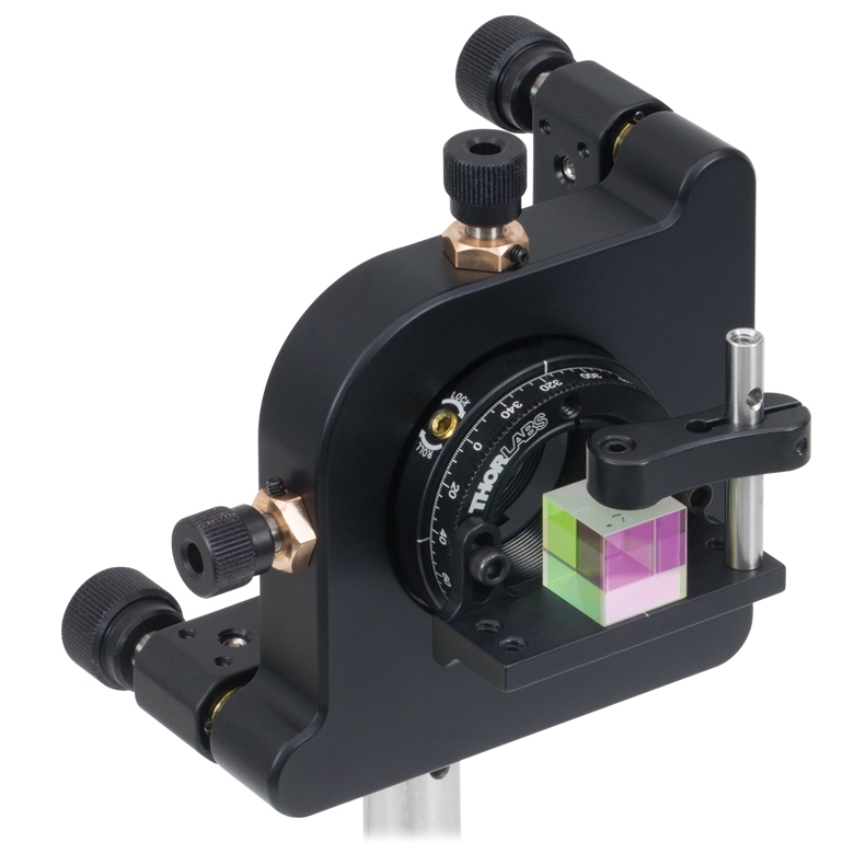
FBTB(/M) | KM100PM(/M) | KM200PM(/M) | KM100B(/M) | KM200B(/M) | K6XS |
| Required Accessories | Base: PCMP(/M) | - | - | Clamp: PM3(/M) or PM4(/M) |
Clamp: PM3(/M) or PM4(/M) |
Clamp: PM3(/M) or PM4(/M) |
Clamp: PM3(/M) or PM4(/M) |
Adapter: K6A1(/M) |
| Mounting Options | Ø1/2" Posts | Ø1/2" Postsa,b | Ø1/2" Posts | Ø1/2" Posts | Ø1/2" Posts | Ø1/2" Posts | Ø1/2" Posts | Ø1/2" Posts |
| Features | Compact | Compact | Glue-In Mount with Precision Tip, Tilt, and Rotation | Tip and Rotation | Tip and Rotation | Kinematic Mount | Kinematic Mount | 6-Axis Mount |
| Compatible Beamsplitter Cube Size(s) |
Up to 20 mm | 10 mm, 1/2", 20 mm, 1", 2" |
5 mm | Up to 20 mmc Up to 1" d |
Up to 20 mmc Up to 1" d Up to 2" e |
Up to 20 mmc Up to 1" d |
Up to 20 mmc Up to 1" d Up to 2" e |
5 mm 10 mm 1/2" |
| Cage System Mounts for Beamsplitter Cubes | |||||||||
|---|---|---|---|---|---|---|---|---|---|
| Click Photo to Enlarge (Cubes Not Included) |
 |
 |
 |
 |
 |
 |
 |
 |
 |
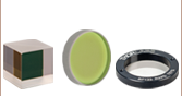
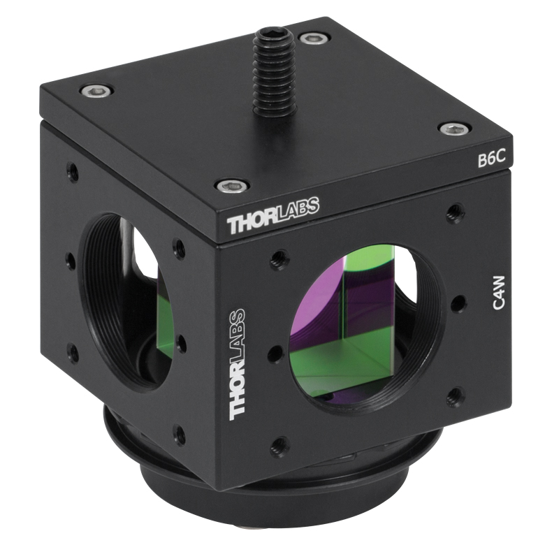
| Item # | Cage Cube: SC6W |
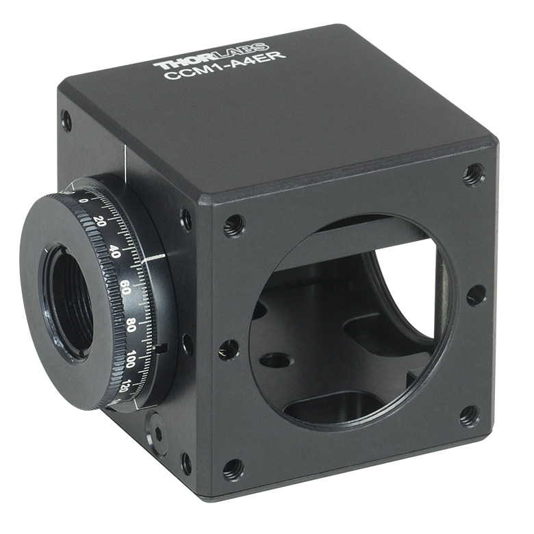
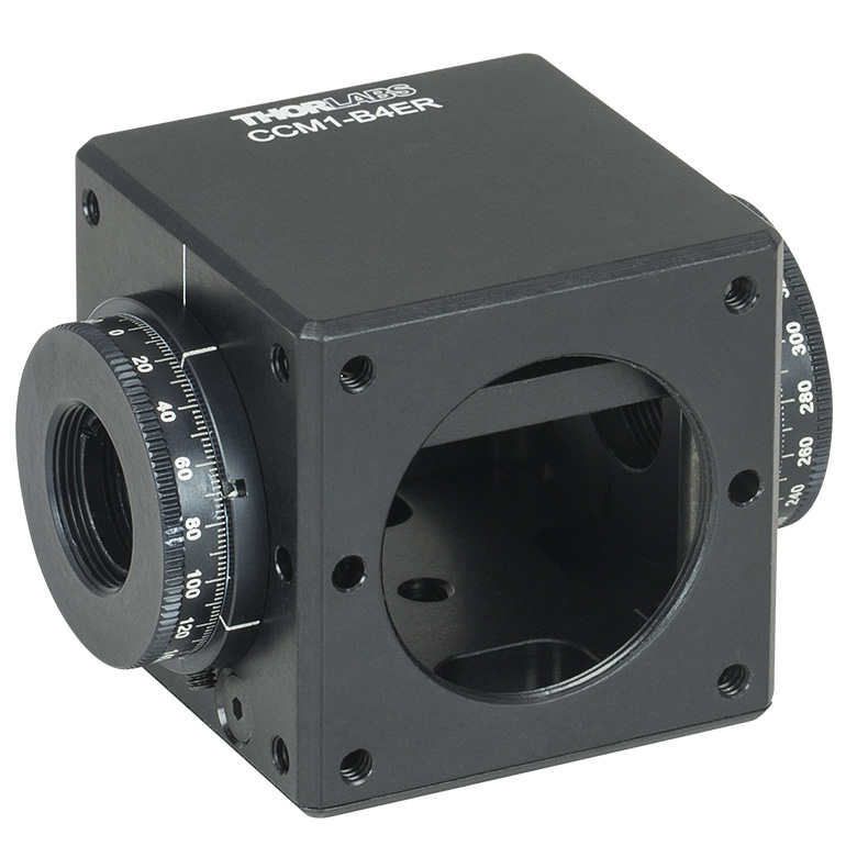
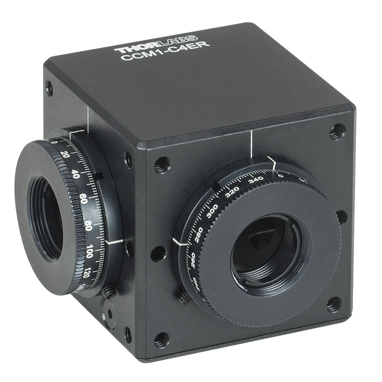
ARV1 | CRM1(/M) or CRM1P(/M) | Cage Cube: C4W or C6W a | CCM1-4ER(/M) | CCM1-A4ER(/M) | CCM1-B4ER(/M) | CCM1-C4ER(/M) | |
| Required Accessories | Clamp: SB6C, Platform: SPM2 |
- | Adapter: K6A1(/M) |
Clamp: B6C, Platform: B3C(/M) or B4C(/M) |
Clamp: B6C, Platform: B3CR(/M) or B4CRP(/M) |
- | - | - | - |
| Mounting Options |
16 mm Cage Systems | 30 mm Cage Systems | 30 mm Cage Systems or Ø1/2" Posts | 30 mm Cage Systems | 30 mm Cage Systems or Ø1/2" Posts | ||||
| Features | Compact | Compact | Rotation Mount | Fixed or Kinematic Platforms | Rotation Platforms | - | One Rotation Mount | Two Rotation Mounts @ 180° | Two Rotation Mounts @ 90° |
| Compatible Beamsplitter Cube Size(s) |
10 mm | 5 mm 10 mm |
5 mm 10 mm 1/2" |
1/2" 20 mm 1" |
5 mm (with BS5CAM Adapter) 10 mm (with BS10CAM Adapter) 1/2" (with BS127CAM Adapter) 20 mm (with BS20CAM Adapter) 1" (Directly Compatible) |
||||
| Posted Comments: | |
Alex Karn
(posted 2024-01-15 08:30:43.21) Does Beam Deviation (for transmitted and reflected beam) depends on wavelength? It looks than our BS014 whith 650-1100 coating significantly deviate our 650nm beam from 1550nm beam (about 1 arcminute). jdelia
(posted 2024-01-25 12:53:49.0) Thank you for contacting Thorlabs. Beam deviation is related to the change in refractive index of beams of different wavelengths passing through the optic. BS014 is designed for 700-1100nm; the max deviation of transmitted beam and reflected beam will be 0° ± 5 arcmin and 90° ± 5 arcmin respectively. We recommend you use BS014 under the design wavelength range. The 650nm/1550nm is out of coating range and its performance will differ from lot to lot, so the phenomenon you observed is normal. Kevin Castrillón
(posted 2023-05-18 12:41:14.963) I am using a beam splitter BS017. When the laser is directed along the marked input arrow, there are beams along all other three directions. Is this behavior normal? Is there any way to prevent the light to come out from the wrong output? jdelia
(posted 2023-05-19 04:43:29.0) Thank you for contacting Thorlabs! Yes, this behavior is normal, the other direction light is caused by surface reflection, you can add a beam block or trap product to absorb this light, or install this BS017 to cage cube (for example, BS20CAM+CCM1-4ER), then add a cap (SM1CP1) to block light. user
(posted 2022-04-26 17:01:38.293) Do you have data concerning the phase change in transmission for the non-polarizing 50:50 700-1100 nm beamsplitter? I would be interested in how well the initial polarization state of the light is preserved after passing through the cube? Thanks. cdolbashian
(posted 2022-05-02 01:33:05.0) Thank you for contacting Thorlabs. We currently do not have data on the performance of these non-polarizing cube beamsplitters in terms of phase change. Stepan V
(posted 2020-08-27 06:52:25.593) Is the wavefront error specification valid for the reflected beam as well? llamb
(posted 2020-09-02 11:29:29.0) Thank you for contacting Thorlabs and for your suggestion about the specs of reflected wavefront error. Currently the wavefront error spec is only valid for the transmitted beam, but we will consider adding a reflected wavefront error spec. Our Tech Support team will reach to you about looking into this spec further. user
(posted 2020-02-06 08:43:16.587) Do you have a 1 inch size of 10:90 (R:T) Non-Polarizing Beamsplitter Cube, 700 - 1100 nm? Thanks. llamb
(posted 2020-02-13 08:49:56.0) Thank you for your feedback. Unfortunately we do not have a 1" version of this particular cube beamsplitter at this time, but I have added your suggestion to our internal product forum for further discussion. Vladimir Makarov
(posted 2019-04-11 22:07:10.89) I am using BS044 beamsplitter. Can you provide estimate of the magnitude of reflections from the internal surfaces of the beamsplitter? For example, how much light will be reflected at ~650-750nm wavelength when incident on internal-to-external surface of the beam splitter?
Is the AR coating effective in this direction as well, or does it only guarantee low reflection (due to AR coating) when light is travelling from air into the glass? YLohia
(posted 2019-04-29 11:07:07.0) Hello, thank you for contacting Thorlabs. The AR coating is effective in this direction of travel as well. The reflectivity on the exit surface of the beamsplitter cube will be ~0.25% due to the AR coating. martin.gersing
(posted 2018-11-07 12:43:11.177) In the Damage Thresholds-Tab for the Non-Polarizing Beam Splitter Cubes (700-1100nm) the maximum cw-Power Density is given with 10W/cm. However for the same Beam Splitter Cubes with other AR-Coatings (400-700nm and 1100-1600nm) this Damage Threshold is significantly higher with 150W/cm.
Is this difference only due to the AR-Coating, or is this maybe just a typo?
Best regards and thanks in advance. YLohia
(posted 2019-01-31 09:23:42.0) Hello, thank you for your feedback. Both of these damage thresholds are correct. There are a couple of reasons for the discrepancy : more absorption in these regions or due to heat dissipation issues (because of differently-sized samples). h.wu
(posted 2017-06-07 10:19:22.77) Is it possible to help us permanently mount BS029 to the 1" beamsplitter cube (like CCM1-BS014/M)? Please include engravings mark (the directions of light propagation) on the outside surface of the cube. Thanks nbayconich
(posted 2017-06-14 10:26:03.0) Thank you for contacting Thorlabs. I will reach out to you directly about offering the BS029 mounted in a cage cube as a special item. m.c.ashby
(posted 2015-11-10 00:31:03.903) Can these splitter cubes be used in reverse to combine two beams (ie one beam incident on the cement side of the beam-splitting interface)? If so, would you still expect a 50:50 attenuation of the power (from a the 50:50 cube)? Thanks smcelwee
(posted 2015-11-16 11:45:36.0) Response from Sean M at Thorlabs: Thank you for your inquiry. These 50:50 beam splitters can also be used in reverse to combine two beams. The coating will be a 50:50 split going in both directions, so you would expect 50% power loss from each of the incident beams.
The most feasible way to combine two beams and keep their power is using a polarizing beam splitter in reverse. However, this requires each input beam to already be linearly polarized. art471
(posted 2014-06-11 19:05:36.06) In the case of Michelson Interferometer using BS029,I'm wondering final intensity ratio of two arms at detector. A beam transmitting at the BS029 will be reflected back by a mirror in the interferometer. Then the beam reflected by the mirror will be reflected by the BS029 to head to detector. In this case, what about the remained intensity of the beam arrived at the detector? Thanks. besembeson
(posted 2014-07-30 06:37:42.0) Response from Bweh at Thorlabs: The intensity ratio will be ~1 assuming the reflectivity of both mirrors is the same. This is because when these combine, it will be 10% of 90% and 90% of 10% of original intensity. adrien.nicolas
(posted 2013-03-01 12:20:41.18) Having tested three 50:50 BS (ref BS005 and BS014) in my lab with 852 nm light, I found them to exhibit the following features: 55% transmission and 36% reflection (9% losses). I tested all four input faces, with any input polarization angle (the transmission and reflection ratios are indeed very well polarization independant) at different angles of incidence and found always the same ratios (up to <2% variations). This seems to be quite far from the specified 50:50 splitting ratio (anyway it is not suitable for interferometric applications where the outputs need carefull balancing). Is this compatible with the guaranteed tolerance on R and T coefficients ? Can you provide NPBS cubes designed to have well balanced outputs at a specified wavelength ?
Thanks in advance tcohen
(posted 2013-03-07 15:27:00.0) Response from Tim at Thorlabs: The specifications for these beamsplitters are Tabs=50+/-15%, Rabs=50+/-15%, Tabs+Rabs>90%, |Ts-Tp|<15% and |Rs-Rp|<15%, 700-1100nm, 0deg AOI as indicated on the drawings. We will update the website to remove any ambiguity in the wording there may currently be. The split ratio will vary with wavelength and I will contact you to discuss solutions for your wavelength directly. tcohen
(posted 2013-01-02 09:39:00.0) Response from Tim at Thorlabs: Although no timeline for this release exists as of yet, we do have this product in development. The complexity of this design is slightly higher than the rest of the products on this page. While an ideal design is being developed we are able to offer the 90:10 (R:T) Cube Beamsplitter (BS029) as a possible alternative. We will increase the priority of this product as a result of your request and inform you upon its release. gediminas.juska
(posted 2012-12-17 16:32:50.987) Are you planning to produce 10:90 (R:T) non-polarizing beamsplitter? What would be the aproximate price of such a custom made element? jlow
(posted 2012-08-30 08:18:00.0) Response from Jeremy at Thorlabs: At larger AOIs, one would typically see a slightly larger polarization dependence and slightly lower polarization dependence at lower AOIs. With that in mind, if you have unpolarized light, then the transmission will be slightly higher at lower (and vice versa). franxm
(posted 2012-08-24 14:00:28.0) How is the transmission affected by incident angle (e.g., 45+15 to 45-15 deg)?
Thanks,
Fran dgardner
(posted 2012-07-03 12:19:00.0) A response from Dave at Thorlabs to cc375: Thank you for pointing out this error. The specs tab now correctly lists the R:T ratio of each cube, which is consistent with the rest of this page. cc375
(posted 2012-07-03 08:36:15.0) You've listed the T/R ratios wrong. On the 'Specs' tab you've shown the BS020 as 30% transmission whereas the 'BS Selection Guide' shows 70% transmission for this cube. |
Beamsplitter Selection Guide
Thorlabs' portfolio contains many different kinds of beamsplitters, which can split beams by intensity or by polarization. We offer plate and cube beamsplitters, though other form factors exist, including pellicle and birefringent crystal. For an overview of the different types and a comparison of their features and applications, please see our overview. Many of our beamsplitters come in premounted or unmounted variants. Below is a complete listing of our beamsplitter offerings. To explore the available types, wavelength ranges, splitting/extinction ratios, transmission, and available sizes for each beamsplitter category, click More [+] in the appropriate row below.Plate Beamsplitters
| Non-Polarizing Plate Beamsplitters |
|---|


| Polarizing Plate Beamsplitters |
|---|
Cube Beamsplitters
| Non-Polarizing Cube Beamsplitters |
|---|


| Polarizing Cube and Polyhedron Beamsplitters |
|---|
| Type | Wavelength Range | Extinction Ratio (TP:TS) |
Typical Transmission | AR Coated Faces |
Cemented | Available Cube/ Polyhedron Side Length |
| Standard: Unmounted 16 mm Cage Cube 30 mm Cage Cube |
420 - 680 nm | >1000:1 |  |
Yes | Yes | Unmounted: 5 mm, 10 mm, 1/2", 20 mm, 1", and 2" Mounted: 20 mm in a 16 mm Cage Cube, 1" in a 30 mm Cage Cube |
| 620 - 1000 nm |  |
|||||
| 700 - 1300 nm |  |
|||||
| 900 - 1300 nm |  |
|||||
| 1200 - 1600 nm |  |
|||||
| Wire Grid: Unmounted 30 mm Cage Cube |
400 - 700 nm | >1000:1 (AOI: 0° - 5°) >100:1 (AOI: 0° - 25°) |
 P-Pol. S-Pol. |
Yes | Yes | Unmounted: 1" Mounted: 20 mm in a 16 mm Cage Cube, 1" in a 30 mm Cage Cube |
| High-Power Laser Line: Unmounted 30 mm Cage Cube |
355 nm | >2000:1 |  |
No | Unmounted: 1/2" and 1" Mounted: 1" in a 30 mm Cage Cube |
|
| 405 nm |  |
|||||
| 532 nm |  |
|||||
| 633 nm |  |
|||||
| 780 - 808 nm |  |
|||||
| 1064 nm |  |
|||||
| Laser Line: Unmounted 30 mm Cage Cube |
532 nm | >3000:1 |  |
Yes | Yes | Unmounted: 10 mm, 1/2", and 1" Mounted: 1" in a 30 mm Cage Cube |
| 633 nm |  |
|||||
| 780 nm |  |
|||||
| 980 nm |  |
|||||
| 1064 nm |  |
|||||
| 1550 nm |  |
|||||
| High-Power, Broadband, High Extinction Ratio Polarizers | 700 - 1100 nm | >1000:1 (700 - 1100 nm) >5000:1 (750 - 1000 nm) >10 000:1 (800 - 900 nm) |
Yes | No | 12.7 mm (Input/Output Face, Square) |
|
| 900 - 1300 nm | >1000:1 (900 - 1300 nm) >10 000:1 (900 - 1250 nm) >100 000:1 (980 - 1080 nm) |
10.0 mm and 5.0 mm (Input/Output Face, Square) |
||||
| Laser-Line Variable | 532 nm | Not Specified | No Graph Available | Yes | Yes | Assembly Mounted in a 30 mm Cage Cube |
| 633 nm | ||||||
| 780 nm | ||||||
| 1064 nm | ||||||
| 1550 nm | ||||||
| Broadband Variable | 420 - 680 nm | Not Specified | No Graph Available | Yes | Yes | Assembly Mounted in a 30 mm Cage Cube |
| 690 - 1000 nm | ||||||
| 900 - 1200 nm | ||||||
| 1200 - 1600 nm | ||||||
| Circular Polarizer/Beamsplitter |
532 nm | Not Specified | No Graph Available | Yes | Yes | Assembly Mounted in a 30 mm Cage Cube |
| 633 nm | ||||||
| 780 nm | ||||||
| 1064 nm | ||||||
| 1550 nm |
Pellicle Beamsplitters
| Non-Polarizing Pellicle Beamsplitters |
|---|


Crystal Beamsplitters
| Polarizing Crystal Beamsplitters |
|---|
Other
| Other Beamsplitters |
|---|

The data above is relative to the power of the incident beam. Note that some light will be absorbed by the beamsplitter coating. The blue shaded regions denote the transmission and reflection bands for which the performance is guaranteed to meet the stated specifications. The data shown here is typical and run-to-run variations will occur within the given specifications. Performance outside the shaded regions is not guaranteed.
| Item # | BS035 | BS038 | BS041 | BS044 | BS026 |
|---|---|---|---|---|---|
| Cube Side Length | 5 mm | 10 mm | 1/2" (12.7 mm) | 20 mm | 1" (25.4 mm) |
| Clear Aperture | >3.5 x 3.5 mm | >8.0 x 8.0 mm | >10.2 x 10.2 mm | >16.0 x 16.0 mm | >20.3 x 20.3 mm |
| Transmitted Wavefront Errora |
<λ/4 | ||||
| Transmitted Beam Deviation |
0° ± 5 arcmin | ||||
| Overall Performanceb |
Tabs = 87 ± 10%, Rabs = 7 +10/-7%, Tabs + Rabs > 85%, |Ts - Tp| < 10%, and |Rs - Rp| < 10% |
Tabs = 87 ± 10%, Rabs = 7 +10/-5%, Tabs + Rabs > 85%, |Ts - Tp| < 10%, and |Rs - Rp| < 10% |
Tabs = 87 ± 10%, Rabs = 7 +10/-7%, Tabs + Rabs > 85%, |Ts - Tp| < 10%, and |Rs - Rp| < 10% |
Tabs = 87 ± 10%, Rabs = 7 +10/-5%, Tabs + Rabs > 85%, |Ts - Tp| < 10%, and |Rs - Rp| < 10% |
|

The data above is relative to the power of the incident beam. Note that some light will be absorbed by the beamsplitter coating. The blue shaded regions denote the transmission and reflection bands for which the performance is guaranteed to meet the stated specifications. The data shown here is typical and run-to-run variations will occur within the given specifications. Performance outside the shaded regions is not guaranteed.
| Item # | BS047 | BS050 | BS053 | BS080 | BS020 |
|---|---|---|---|---|---|
| Cube Side Length | 5 mm | 10 mm | 1/2" (12.7 mm) | 20 mm | 1" (25.4 mm) |
| Clear Aperture | >3.5 x 3.5 mm | >8.0 x 8.0 mm | >10.2 x 10.2 mm | >16.0 x 16.0 mm | >20.3 x 20.3 mm |
| Transmitted Wavefront Errora |
<λ/4 | ||||
| Transmitted Beam Deviation | 0° ± 5 arcmin | ||||
| Overall Performanceb | Tabs = 62 ± 10%, Rabs = 27 ± 10%, and Tabs + Rabs > 80%, |Ts - Tp| < 10% and |Rs - Rp| < 10% |
||||
The data above is relative to the power of the incident beam. Note that some light will be absorbed by the beamsplitter coating. The blue shaded regions denote the transmission and reflection bands for which the performance is guaranteed to meet the stated specifications. The data shown here is typical and run-to-run variations will occur within the given specifications. Performance outside the shaded regions is not guaranteed.
| Item # | BS008 | BS011 | BS005 | BS017 | BS014 | BS032 |
|---|---|---|---|---|---|---|
| Cube Side Length | 5 mm | 10 mm | 1/2" (12.7 mm) | 20 mm | 1" (25.4 mm) | 2" (50.8 mm) |
| Clear Aperture | >3.5 x 3.5 mm | >8.0 x 8.0 mm | >10.2 x 10.2 mm | >16.0 x 16.0 mm | >20.3 x 20.3 mm | >40.6 x 40.6 mm |
| Transmitted Wavefront Errora |
<λ/4 | <λ | ||||
| Transmitted Beam Deviation | 0° ± 5 arcmin | |||||
| Overall Performanceb | Tabs = 47 ± 10%, Rabs = 47 ± 10%, and Tabs + Rabs > 90%, |Ts - Tp| < 10% and |Rs - Rp| < 10% |
Tabs= 47 ± 10%, Rabs= 47 ± 10%, Tabs + Rabs > 85% Tavg + Ravg > 90% |Ts - Tp| < 10% and |Rs - Rp| < 10% |
||||
| Damage Threshold |
Pulsed: 0.25 J/cm2 (810 nm, 10 ns, 10 Hz, Ø0.166 mm) CWc: 10 W/cm (1070 nm, Ø1.012 mm) |
|||||
The data above is relative to the power of the incident beam. Note that some light will be absorbed by the beamsplitter coating. The blue shaded regions denote the transmission and reflection bands for which the performance is guaranteed to meet the stated specifications. The data shown here is typical and run-to-run variations will occur within the given specifications. Performance outside the shaded regions is not guaranteed.
| Item # | BS056 | BS059 | BS062 | BS065 | BS023 |
|---|---|---|---|---|---|
| Cube Side Length | 5 mm | 10 mm | 1/2" (12.7 mm) | 20 mm | 1" (25.4 mm) |
| Clear Aperture | >3.5 x 3.5 mm | >8.0 x 8.0 mm | >10.2 x 10.2 mm | >16.0 x 16.0 mm | >20.3 x 20.3 mm |
| Surface Flatnessa | - | λ/10 | |||
| Transmitted Wavefront Errora |
<λ/4 | ||||
| Transmitted Beam Deviation | 0° ± 5 arcmin | <5 arcmin | |||
| Overall Performanceb | Tabs = 27 ± 10%, Rabs = 67 +5/-15%, and Tabs + Rabs > 85%, |Ts - Tp| < 10% and |Rs - Rp| < 10% |
||||

The data above is relative to the power of the incident beam. Note that some light will be absorbed by the beamsplitter coating. The blue shaded regions denote the transmission and reflection bands for which the performance is guaranteed to meet the stated specifications. The data shown here is typical and run-to-run variations will occur within the given specifications. Performance outside the shaded regions is not guaranteed.
| Item # | BS068 | BS071 | BS074 | BS077 | BS029 |
|---|---|---|---|---|---|
| Cube Side Length | 5 mm | 10 mm | 1/2" (12.7 mm) | 20 mm | 1" (25.4 mm) |
| Clear Aperture | >3.5 x 3.5 mm | >8.0 x 8.0 mm | >10.2 x 10.2 mm | >16.0 x 16.0 mm | >20.3 x 20.3 mm |
| Transmitted Wavefront Errora |
<λ/4 | ||||
| Transmitted Beam Deviation | 0° ± 5 arcmin | ||||
| Overall Performanceb | Tabs = 7 +10/-5%, Rabs = 87 ± 10%, and Tabs + Rabs > 85%, |Ts - Tp| < 10% and |Rs - Rp| < 10% |
||||