 Products Home / Polarization Optics / Polarizers / Wire Grid Polarizers / Wire Grid Polarizers on Glass Substrates
Wire Grid Polarizers on Glass Substrates
- Polarizes Wavelengths from 420 to 700 nm or 250 nm to 4 µm
- High Transmission and Extinction Ratio
- Protective Glass Cover
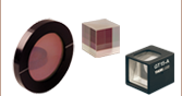
WP50L-UB
50.0 mm x 50.0 mm
WP25L-UB
25.0 mm x 25.0 mm
WP12L-VIS
12.5 mm x 12.5 mm
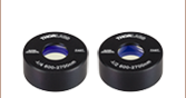
WP25M-VIS
Ø25.0 mm


Please Wait

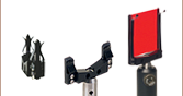
How to Determine the Polarization Axis

Click to Enlarge Variable Polarizing Attenuator Made with Two WP50L-VIS Polarizers
Features
- Large Field of View
- Available Extinction Ratios
- >800:1 (-VIS)
- Up to 10 000:1 (-UB)
- Available Polarization Range:
- 420 - 700 nm (-VIS)
- 250 nm - 4 µm (-UB)
- Multiple Sizes Available
- 12.5 mm x 12.5 mm (Unmounted)
- Ø25 mm (Mounted)
- 25 mm x 25 mm (Unmounted)
- 50 mm x 50 mm (Unmounted)
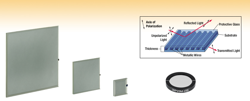
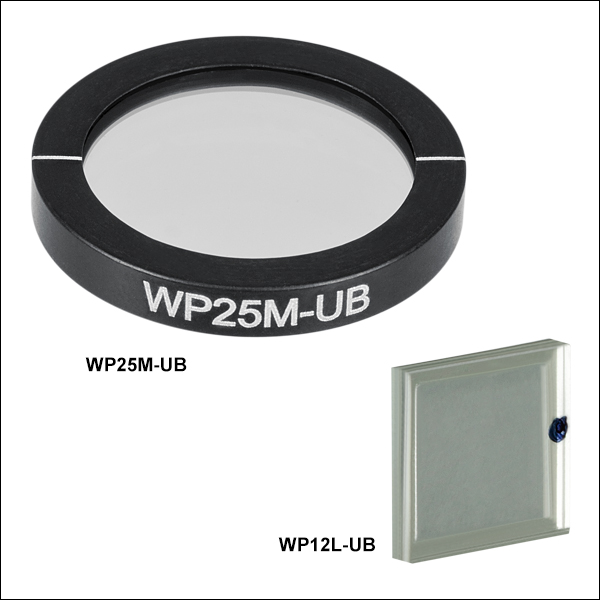
These polarizers consist of an array of parallel metallic wires sandwiched between a fused silica (-UB) or Eagle XG (-VIS) glass substrate. Featuring high transmission (see Graphs tab) and a high maximum operating temperature (200 °C for the unmounted square polarizers, 93 °C for the mounted round polarizers), wire grid polarizers are an alternative to both traditional film-based polarizers and holographic wire grid polarizers. Additionally, our -VIS wire grid polarizers have an antireflection coating for the 400 - 700 nm deposited on the back of substrate as well as on both sides of the cover glass.
Since the wire grid is prone to damage, the protective glass cover serves to reduce this risk. In addition, the glass surfaces may be cleaned, which extends the typical working lifetime when compared to unprotected wire grid polarizers.
Wire grid polarizers transmit radiation with an electric field vector perpendicular to the wire and reflect radiation with the electric field-vector parallel to the wire. The direction of polarized transmitted light is marked by a small dot on the square polarizers and by a line on the round polarizers (see diagrams to the right). Due to surface reflections, the reflected beam contains both polarizations. Please note that the mark on these wire grid polarizers indicates the axis of polarization and not the orientation of the wires (see the diagrams to the right).
The extinction ratio of a polarizer is a measure of its ability to attenuate light polarized perpendicular to the polarizer's transmission axis. The extinction ratio (ER) can be calculated by measuring the ratio of the maximum transmission (Tmax) when the polarizer is aligned to the polarization axis to the minimum transmission (Tmin) when the polarizer is rotated by 90°.

Click to Enlarge
Raw Data
The shaded region indicates the specified operating wavelength range of the polarizer.
Click to Enlarge
Raw Data
Note: For wavelengths >2.6 μm, the Ultrabroadband Wire Grid Polarizer will continue to polarize the light transmitted through the fused silica substrate.
The data presented above was taken from a single production run. Performance will vary from lot to lot, but all of the polarizers available here are guaranteed to meet the specifications provided in the tables below.
| Posted Comments: | |
Won-il Lee
(posted 2024-04-09 17:29:42.68) About WP25M-UB
A femtosecond laser has an average output of 5W, pulse energy of 500nJ, pulse maximum power of 2MW, wavelength of 1040nm.
I want to know if WP25M-UB is safe from Laser Damage, and if not, I wonder to what extent it should be safe to use it with limited output. jpolaris
(posted 2024-04-22 03:50:51.0) Thank you for contacting Thorlabs. Unfortunately, we do not have formal femtosecond LIDT data for these wire grid polarizers at this time. However, in some cases, we can compare to reports we've received in the past from other customers regarding LIDT. I have reached out to you directly to discuss in more detail. Sub Kim
(posted 2024-02-13 11:39:46.347) Hello.
As far as I know, the wire grid polarizer has the polarization direction and wire pattern direction perpendicular to each other.
Then, if the axis of the products is 0 degrees, the actual wire pattern is 90 degrees? cdolbashian
(posted 2024-02-19 10:49:01.0) Thank you for reaching out to us with this inquiry. Your understanding is correct. Thank you for clarifying! bob henderson
(posted 2023-11-09 11:10:31.27) is the WP25M-IRA polariser suitable to use with the MLQD4500 laser source? I am interested to know if this polariser will cope with the laser power density. cdolbashian
(posted 2023-11-16 02:59:55.0) Thank you for reaching out to us with this inquiry. These two components will be compatible based on our own knowledge of the damage threshold for these polarizers. Geer Teng
(posted 2023-11-06 13:26:20.927) Hi, may I request for a transmission raw data at different wavelengths of the WP25M-VIS? I ordered this polarizer last Dec., but it seems there's no transmission raw data on the website. jdelia
(posted 2023-11-08 10:24:15.0) Thank you for contacting Thorlabs. You can access the raw data transmission data for the WP25M-VIS by going to the "Graphs" tab of the product family page. Under the transmission graph on the left, you can then click on the "Raw Data" hyperlink to download an Excel file. user
(posted 2023-11-06 12:17:12.91) When you compare the wavefront of the transmitted light after the light passes the wire grid polarizers and only the substrate, could you recognize the effect of the grid on the wavefront of the transmitted light? cdolbashian
(posted 2023-11-15 01:37:45.0) Thank you for reaching out to us with this inquiry. The expected transmitted wavefront error should be <λ/10. Samuel E
(posted 2023-10-11 13:12:39.91) Hi
Do you have an estimate for the damage threshold of this wire grid polariser at ~50fs? It doesn't have to be precise, an order of magnitude would do.
Thanks. ksosnowski
(posted 2023-10-12 11:34:26.0) Hello Samuel, thanks for reaching out to Thorlabs. As we currently have not tested these with ultrafast pulses, we are unable to provide a formal damage threshold for these polarizers. In some cases we may able to reference previous customer experiences with these optics as a guideline. I have reached out directly to discuss your application in further detail. Guillaume VIENNE
(posted 2023-09-21 07:16:55.447) Hello,
I am looking for polarizer with LIDT sufficient for 488nm 1W CW laser beam 500µm in diameter, with ER>1000, and preferably mounted.
Which option are suitable? (some LP's LIDTs are not indicated on your website)
Cheers! cdolbashian
(posted 2023-10-03 09:22:38.0) Thank you for reaching out to us with this inquiry! I have contacted you directly to discuss polarizer options in terms of performance and mechanical dimensions. There are some tradeoffs between the different varieties of polarizers, and these need to be considered to find which component best satisfies your requirements. 训鹏 宋
(posted 2023-09-06 13:30:02.593) I would like to customize a 4.5mm *4.5mm grid polarizer. Please provide delivery time and quotation. cdolbashian
(posted 2023-10-19 01:23:21.0) Thank you for reaching out to us with this inquiry. While we cannot provide you a quote via the feedback platform here, I have reached out to you directly to discuss this. For future custom quotation requests, please contact your local tech support office. Our list of global offices and respective contact information can be found here: https://www.thorlabs.com/locations.cfm user
(posted 2023-02-20 19:05:54.293) What is the damage threshold for WP25L-VIS? cdolbashian
(posted 2023-04-03 08:55:25.0) Thank you for reaching out to us with this inquiry! While we do not have a specific damage threshold tested for this component, we can provide a general guideline for CW damage. I have reached out to you directly with this information. Gil Markovich
(posted 2022-08-10 15:58:18.247) Could you please indicate the damage threshold for the visible and ultrabroadband wire grid polarizers for CW illumination? Say at 532 nm. cdolbashian
(posted 2022-08-18 02:54:34.0) Thank you for reaching out to us with this inquiry. As we have not extensive damage threshold testing on this device, we would not feel comfortable sharing a specific damage threshold. I have contacted you directly to discuss your laser parameters and the compatibility with our products. Siyu LIU
(posted 2022-05-30 14:10:53.41) Hello!
I have a few questions about the polarizer (WP25M-VIS)
1. What's the distance between the wires and what is the width of the metal wires?
2. What is the thickness of the base and the protective glass?
3. The metal wires are on which side of the polarizer? ksosnowski
(posted 2022-06-06 05:05:18.0) Thanks for reaching out to Thorlabs. The wire pitch is 144nm, with a feature size of ~65nm and duty cycle of ~45/55 (Open/Close). Operationally, the wires interact with the light in a similar way as a thin film would. The transmitted light passes with minimal interaction with the wires and the reflected light ‘sees’ the wires practically as an Al mirror at those wavelengths. The back scatter would have minimal diffraction. The Substrate Thickness (Eagle XG) is 1.53 ± 0.20 mm. Unlike the Holographic Wire Grid Polarizers, these are "sandwiched" by the substrate and a protective layer, so the wires are in the middle rather than the outside. user
(posted 2021-12-10 04:36:32.517) Can you please clarify the specification "Angle of incidence +-20 deg". Is this acceptance range or does this mean that the incident light must have 20 deg AOI? YLohia
(posted 2021-12-10 09:27:16.0) Thank you for contacting Thorlabs. This refers to the acceptance range of the optic. Gregor Schiwietz
(posted 2021-08-28 13:34:44.88) How large is the
Transmitted Wavefront Distortion
for the
Wire Grid Polarizers of types
WP25M-VIS and
WP25L-VIS? YLohia
(posted 2021-09-09 03:38:54.0) Thank you for contacting Thorlabs. While we don't formally spec the TWD for these optics due to the lack of comprehensive data, based on preliminary testing we expect it to be around ~lambda/4 P-V. Please note that since this is not a formal spec, we cannot provide any guarantees that the piece you receive will perform up to this standard. Petros Gasparyan
(posted 2020-09-16 06:06:13.603) Dear responsible pearson
Hello. My name is Petros.
I have a question about your VIS wire grid polarizers.
Is it possible to use as a filter in cameras?
If you have any information about their wavefront distortion, please inform.
Best Regards
Petros gasparyan. YLohia
(posted 2020-09-17 02:38:23.0) Hello Petros, thank you for contacting Thorlabs. It is indeed possible to use this as filter in cameras, but the mounting will depend on your camera hardware. I have reached out to you directly to discuss further. Michael Lim
(posted 2020-09-07 14:12:59.933) I am interested in using the WP25L-VIS within an extended cavity diode laser operating near 700nm. In order to do this, i need to calculate the diffraction of the reflected polarization component, which require knowledge of the spacing and thickness of the metallic wires in the grid. Can you please provide this data and/or comment on the diffraction behavior of the block polarization component? Please contact me at lim@rowan.edu at your earliest convenience.
Thanks,
Michael Lim YLohia
(posted 2020-09-09 03:28:10.0) Hello Michael, thank you for contacting Thorlabs. The wire pitch is 144nm, with a feature size of ~65nm and duty cycle of ~45/55 (Open/Close).
Operationally, the wires interact with the light in a similar way as a thin film would. The transmitted light passes with minimal interaction with the wires and the reflected light ‘sees’ the wires practically as an Al mirror at those wavelengths. The back scatter would have minimal diffraction. user
(posted 2019-08-29 20:08:39.103) What is the uncertainty in the orientation of the wires with respect to the outer 50x50 mm square? YLohia
(posted 2019-09-03 10:01:11.0) Hello, the tolerance on the orientation of the polarization axis with respect to the outer square is ±0.5°. ruizhi.zheng
(posted 2018-11-23 16:12:46.153) Could you please provide the reflection graph of TE mode (the polarized light be reflected)? nbayconich
(posted 2019-01-04 09:26:30.0) Thank you for contacting Thorlabs. I will reach out to you directly with some data we have scanned internally. We will make this data available on our webpage once all the necessary transmission & reflection scans are completed. Diane.Beamer
(posted 2017-07-07 16:55:43.433) i have two Thorlabs WPM25M-VIS wire grid polarizers; i used one as a polarization generator and one as an analyzer. i get max transmission when the transmission axes are crossed. How is this possible? for instance i get over 4 mW when analyzer is at 90, and generator is at 0, and i get about 1 mW when both transmission axes are parallel to one another. i took about 40 readings in a calibration exercise, with consistent measurements. is it possible one of them is mismarked on transmission axis? i reversed the orientation of the generator but got the same thing. tfrisch
(posted 2017-08-07 10:43:47.0) Hello, thank you for contacting Thorlabs. Assuming there are no other optics in between them that may be birefringent, and assuming that you are referring to the engraving on the polarizer housing, and not a secondary mount (like a rotation mount), it sounds like at least one of them is mislabeled. I will reach out to you about replacing these. Petr.bouchal
(posted 2017-05-24 15:21:43.423) Hello,
could you provide me with information on thickness of WP25M-VIS. I supposse that thickness 3.5mm includes housing of WP. I am interested in thickness of substrate plus protective glass. Thanks.
Regards, P.B. nbayconich
(posted 2017-06-12 02:33:34.0) Thank you for contacting Thorlabs. The total thickness of just the WP25M-VIS polarizer itself without the mount is 1.53mm. A techsupport representative will contact you directly. robert.carlson
(posted 2017-04-11 15:41:09.49) I would appreciate a quote for a 50x50 optic (WP50L-UB) cut to provide four 15x15 pieces. (The 12.5x12.5 part is a little too small for my application.) I can accept best effort, looking for as much C.A. as possible on the 15x15 pieces.
Please email me a custom quote for this.
Thanks! tfrisch
(posted 2017-04-19 05:01:56.0) Hello, thank you for contacting Thorlabs. I will forward your request to our Tech Support team for quoting. Unfortunately, wire grid polarizers cannot be cut, so these would need to be made from scratch. sibo
(posted 2017-04-08 10:25:19.133) Why for the Ultra Broadband Wire Grid Polarizers the values of the extinction ratio given in the table and the ones given in the graph are so different? For instance between 600 and 2600 nm, the ER is 10000 form the graph and 1000 form the table. tcampbell
(posted 2017-04-10 08:55:38.0) Response from Tim at Thorlabs: thank you for your feedback. The graphs represent typical data, but performance may vary between production runs. The values in the tables further down on the page are guaranteed specifications for these items. qkrwhdrbs
(posted 2017-02-07 05:10:08.293) Hello.
I am considering buy "WP25M-UB".
Before I order it, I have to consider damage threshold. So Can you give me damage threshold imformation?
Thank you. tfrisch
(posted 2017-02-15 01:12:45.0) Hello, thank you for contacting Thorlabs. I will reach out to you about your laser specs. mostert
(posted 2016-07-23 17:43:19.033) Question: Do you have ER and transmission curve data for light entering the WP25M-VIS at angles of incidence >20 degrees? bernd-claus.weber
(posted 2016-06-13 15:36:47.087) Question:
What is the thickness of the actual wire grid layer?
Is this wire grid layer exactly in the center of the glass substrate?
Reason for these questions:
We'd like to remove glass from both sides in order to get a thinner filter besembeson
(posted 2016-06-15 09:58:52.0) Response from Bweh at Thorlabs USA: You can't have the glass removed from both sides. The thickness of the wire grid on substrate is 0.7mm. There is a cover glass that has a thickness of 0.8mm. We can provide a special with the cover glass removed. hl4
(posted 2016-04-01 18:16:26.227) Do you also Extiction Ratio and Transmission Data for wavelength above 900 nm lets say up to 1100 nm? besembeson
(posted 2016-04-05 09:13:23.0) Response from Bweh at Thorlabs USA: Beyond 900nm, the transmission continues to drop and the ER fluctuates. I will share example data with you via email. user
(posted 2016-01-07 18:05:55.623) Another request for a damage threshold:
I need to polarize a 120mJ/pulse, 20 Hz Excimer Laser at about 350 nm. Beam cross section about 2 cm². Would you consider that safe? besembeson
(posted 2016-01-12 04:39:15.0) Response from Bweh at Thorlabs USA: Thanks for contacting Thorlabs. We don't have test data yet for these. I will however need your pulse length (that will determine peak powers) to provide suggestions on using this. Please contact me at techsupport@thorlabs.com. IGKIOU
(posted 2014-10-02 16:24:37.173) Hi, are there larger versions of these polarizers available? I would be particularly interested in 50mm round and 75mm x 75 mm square versions of the VIS wire grid polarizers. Thank you in advance. besembeson
(posted 2014-10-09 10:39:37.0) Response from Bweh at Thorlabs: We can provide such larger custom polarizers. I will follow-up with you by email to know which version you would be interested in. M.Eggens
(posted 2014-09-15 14:57:42.063) Hi, which material (glue?) is used to bond both substrate and the cover glass? Is the bonding resistant to demineralised water? Thanks a.andreski
(posted 2014-04-24 10:17:28.55) Hi. What is the wavefront distortion of these optics? Thanks! jlow
(posted 2014-05-05 03:35:38.0) Response from Jeremy at Thorlabs: The transmitted wave front error is typically <1/10 wave. sayu
(posted 2014-03-24 10:32:48.737) Can you provide the parallelism of polarizer? cdaly
(posted 2014-04-10 05:36:57.0) Response from Chris at Thorlabs: We have a tested value for parallelism spec of less than 1 arcmin. This is a typical value though, not a guarantee. If you would like to have some tested before purchase, we can set this up as a custom for you. I will contact you directly to discuss this further. ndabashigeo
(posted 2014-02-20 19:17:14.25) what is the damage threshold of these products at 532 nm pulsed? jlow
(posted 2014-03-05 11:06:33.0) Response from Jeremy at Thorlabs: We do not have data for the damage threshold for 532nm but it is estimated to be around 0.08J/cm^2 (blocking) and 0.21 J/cm^2 (passing) for 10ns pulse. ryseck
(posted 2013-08-20 09:12:33.34) Dear Ladies and Gentlemen,
Do you have data for the damage threshold for wire grid polarizers when using a pulsed Nd:YAG-laser with a wavelength of 266 nm (4th harmonic) and a pulse duration of ~5 ns?
Thank you very much,
best wishes
Gerald Ryseck jlow
(posted 2013-09-17 16:19:00.0) Response from Jeremy at Thorlabs. We do not have a spec for the laser damage threshold at 266nm for 5ns pulse. However, based on a past test, the damage threshold should be around 0.05 J/cm^2 (blocking) and 0.15 J/cm^2 (passing), tested with a 13ns pulse width, 100kHz rep rate, 266nm laser. tcohen
(posted 2013-02-26 14:46:00.0) Response from Tim at Thorlabs: Thank you for contacting us! You will find nominal transmission and extinction ratio data at 400nm available by clicking on the “Graphs” tab. The WP25M-UB is in stock and available to ship immediately. As for LIDT, we do not currently have data on this. We are looking into this and I have contacted you to keep you updated. user
(posted 2013-02-11 13:08:34.953) What mounts are available for the WP25L-UB if manual rotation of the polarizer is needed? cdaly
(posted 2013-02-14 12:29:00.0) Response from Chris at Thorlabs: Thank you for using our web feedback. We do not have a mount which would allow for this square optic to be rotated. We have recently released a 25mm round version which lends itself much more easily to being rotated in many of our standard rotation mounts. The part number is WP25M-UB. tcohen
(posted 2012-05-08 09:31:00.0) Response from Tim at Thorlabs: Thank you for your feedback! Our wire grid polarizers have a wide acceptance angle allowing for +/- 20 degrees AOI. user
(posted 2012-05-05 21:08:12.0) What is the recommended AOI for those polarizets? tcohen
(posted 2012-03-29 11:31:00.0) Response from Tim at Thorlabs: Thank you for your feedback! We offer a variety of polarizers to choose from and it is useful for prospective users to have this information before making a decision. Thank you for sharing this information! user
(posted 2012-03-24 13:57:21.0) These perform really well, but they also introduce a spectral modulation onto any polychromatic beam incident onto them, presumably due to interference between the sandwiched glass layers. This makes them less useful for spectrally-resolved applications. bdada
(posted 2012-02-24 10:18:00.0) Response from Buki at Thorlabs to udierksheide:
Thank you for your feedback. We do not currently have tested damage threshold data for these wire grid polarizers but I will look into this further to advise if your light source is suitable. We do not currently have a solution for mounting this polarizer in our SM1 tubes but I will post an update after discussing this with our engineering team. udierksheide
(posted 2012-02-16 14:02:40.0) Dear,
I would like to know the damage treshhold.
I need 10J/cm2 10ns 10Hz @ 532nm or more.
Please let me know the treshhold and how I could mount it in a SM1 compatible cube.
Regards
Uwe Dierksheide bdada
(posted 2011-10-21 14:18:00.0) Response from Buki at Thorlabs:
To the last two posters, thank you for your feedback and for your interest in our wire grid polarizers. We do not have tested damage threshold data for the wire grid polarizers so we are unsure how it will perform with femtosecond lasers. Fused silica has a GVD of ~53 fs^2/mm from 500-900nm. Please contact TechSupport@thorlabs.com if you have further questions. shaba82
(posted 2011-10-19 14:18:18.0) Is this product applicable to femtosecond laser pulses?
If it is, can you send me the group-delay dispersion(GDD) data of this product from 500-nm to 900-nm wavelength range? falk.eilenberger
(posted 2011-09-22 17:05:41.0) to whom it may concern,
I am in need of a polarizer for a high power application of a fs-source. The source is rated at 1.5 Watts average power, with roughly 35fs pulse length (1 kHz) running at 800 (+/- 100) nm. Are your wrie-grid polarizers suitable such a laser beam?
Thank you very much in advance
Falk Eilenberger |
Polarizer Selection Guide
Thorlabs offers a diverse range of polarizers, including wire grid, film, calcite, alpha-BBO, rutile, and beamsplitting polarizers. Collectively, our line of wire grid polarizers offers coverage from the visible range to the beginning of the Far-IR range. Our nanoparticle linear film polarizers provide extinction ratios as high as 100 000:1. Alternatively, our other film polarizers offer an affordable solution for polarizing light from the visible to the Near-IR. Next, our beamsplitting polarizers allow for use of the reflected beam, as well as the more completely polarized transmitted beam. Finally, our alpha-BBO (UV), calcite (visible to Near-IR), rutile (Near-IR to Mid-IR), and yttrium orthovanadate (YVO4) (Near-IR to Mid-IR) polarizers each offer an exceptional extinction ratio of 100 000:1 within their respective wavelength ranges.
To explore the available types, wavelength ranges, extinction ratios, transmission, and available sizes for each polarizer category, click More [+] in the appropriate row below.
| Wire Grid Polarizers |
|---|
| Film Polarizers |
|---|


| Beamsplitting Polarizers |
|---|
| Polarizer Type | Wavelength Range | Extinction Ratio | Transmissiona | Available Sizes |
| Polarizing Plate Beamsplitters | 405 nm | >10 000:1 | Ø1" and 25 mm x 36 mm | |
| 532 nm | ||||
| 633 nm | ||||
| 780 nm | ||||
| 808 nm | ||||
| 1030 nm | ||||
| 1064 nm | ||||
| 1310 nm | ||||
| 1550 nm | ||||
| Polarizing Bandpass Filters | 355 nm +6 nm / -9 nm | 1 000 000:1 | 25.2 mm x 35.6 mm | |
| Broadband Polarizing Beamsplitter Cubes (Unmounted, 16 mm Cage Cube, or 30 mm Cage Cube) |
420 nm - 680 nm | 1000:1e |  |
5 mm, 10 mm, 1/2", 20 mmf, 1"f, and 2" |
| 620 nm - 1000 nm |  |
|||
| 700 nm - 1300 nm |  |
|||
| 900 nm - 1300 nm |  |
|||
| 1200 nm - 1600 nm |  |
|||
| Wire Grid Polarizing Beamsplitter Cubes (Unmounted or 30 mm Cage Cube) |
400 nm - 700 nm | >1 000:1 (AOI: 0° - 5°) >100:1 (AOI: 0° - 25°) |
 P-Pol. S-Pol. |
1"f |
| Laser-Line Polarizing Beamsplitter Cubes (Unmounted or 30 mm Cage Cube) |
532 nm | 3000:1 |  |
10 mm, 1/2", 1"f |
| 633 nm |  |
|||
| 780 nm |  |
|||
| 980 nm |  |
1"f | ||
| 1064 nm |  |
10 mm, 1/2", 1"f | ||
| 1550 nm |  |
|||
| High-Power Laser-Line Polarizing Beamsplitter Cubes (Unmounted or 30 mm Cage Cube) | 355 nm | 2000:1 | 1/2" and 1"f | |
| 405 nm |  |
|||
| 532 nm | ||||
| 633 nm | ||||
| 780 - 808 nm |  |
|||
| 1064 nm | ||||
| High-Power, Broadband, High Extinction Ratio Polarizers | 700 nm - 1100 nm | > 1000:1 (700 - 1100 nm) > 5000:1 (750 - 1000 nm) > 10 000:1 (800 - 900 nm) |
12.7 mm (Input/Output Face, Square) |
|
| 900 nm - 1300 nm | >1000:1 (900 - 1300 nm) >10 000:1 (900 - 1250 nm) >100 000:1 (980 - 1080 nm) |
10 mm and 5 mm (Input/Output Face, Square) |
||
| Calcite Beam Displacers | 350 nmg - 2.3 µm (Uncoated) | - | 10 mmb (Clear Aperture, Square) |
|
| Yttrium Orthovanadate (YVO4) Beam Displacers | 488 nm - 3.4 µm (Uncoated) | - | >3 mm x 5 mm Ellipseh (Clear Aperture) |
|
| 2000 nm (V Coated) |
| alpha-BBO Polarizers |
|---|
| Calcite Polarizers |
|---|
| Quartz Polarizers |
|---|
| Magnesium Fluoride Polarizers |
|---|
| Yttrium Orthovanadate (YVO4) Polarizers |
|---|
| Rutile Polarizers |
|---|

 Zoom
Zoom| Specifications | ||||
|---|---|---|---|---|
| Item # | WP12L-VIS | WP25M-VIS | WP25L-VIS | WP50L-VIS |
| Substrate | EAGLE XG | |||
| Polarization Wavelength Range | 420 - 700 nm | |||
| Extinction Ratioa | >800:1 (Average Over Wavelength Range) | |||
| AR Coatingb | 400 - 700 nm (Ravg <1%) | |||
| Transmission | >83% | |||
| Size | 12.5 mm x 12.5 mm | Ø25.0 mm | 25.0 mm x 25.0 mm | 50.0 mm x 50.0 mm |
| Dimensional Tolerance (Length or Diameter) |
±0.2 mm | +0.0/-0.1 mm | ±0.2 mm | |
| Clear Aperture | 10.5 mm × 10.5 mm | Ø19 mm | 21.0 mm × 21.0 mm | 48.0 mm × 48.0 mm |
| Thickness | 1.53 ± 0.20 mm | 3.5 ± 0.10 mm | 1.53 ± 0.20 mm | |
| Angle of Incidence | ±20° | |||
| Thermal Expansion | 37.6 x 10⁻⁷/°C | |||
| Surface Quality | 80-50 Scratch-Dig | |||
| Operating Temperature | -40 to 200 °C | -40 to 93 °C | -40 to 200 °C | |

 Zoom
Zoom| Specifications | ||||
|---|---|---|---|---|
| Item # | WP12L-UB | WP25M-UB | WP25L-UB | WP50L-UB |
| Substrate | Fused Silica | |||
| Polarization Wavelength Range | 250 nm - 4 µm | |||
| Extinction Ratioa | 250 nm - 4 µm: >10:1 300 nm - 4 µm: >100:1 600 nm - 4 µm: >1000:1 2.25 µm - 4 µm: >10 000:1 |
|||
| Transmission | >75% (@ 450 nm) | |||
| Size | 12.5 mm x 12.5 mm | Ø25.0 mm | 25.0 mm x 25.0 mm | 50.0 mm x 50.0 mm |
| Dimensional Tolerance (Length or Diameter) |
±0.4 mm | +0.0/-0.1 mm | ±0.4 mm | |
| Clear Aperture | 10.5 mm × 10.5 mm | Ø19 mm | 21.0 mm × 21.0 mm | 48.0 mm × 48.0 mm |
| Thickness | 2.2 mm ±0.3 mm | 3.5 mm | 2.2 ±0.3 mm | |
| Angle of Incidence | ±20° | |||
| Thermal Expansion | 5.5 x 10⁻⁷/°C | |||
| Surface Quality | 80-50 Scratch-Dig | |||
| Operating Temperature | -40 to 200 °C | -40 to 93 °C | -40 to 200 °C | -40 to 200 °C |