 Products Home / Polarization Optics / Polarizers / Wire Grid Polarizers / MIR Wire Grid Polarizers on Silicon Substrates
MIR Wire Grid Polarizers on Silicon Substrates
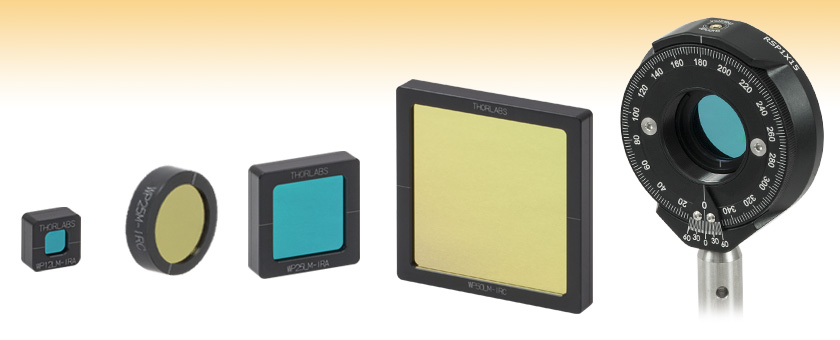
- Wavelength Range: 3 - 5 µm or 7 - 15 µm
- Ø25.0 mm, 12.5 mm Square, 25.0 mm Square, or 50.0 mm Square
- >1000:1 or >10 000:1 Extinction
WP12LM-IRA
12.5 mm x 12.5 mm
WP25M-IRC
Ø25.0 mm
WP25LM-IRA
25.0 mm x 25.0 mm
WP50LM-IRC
50.0 mm x 50.0 mm
WP25M-IRA
Mounted in an
RSP1X15 Rotation
Mount


Please Wait
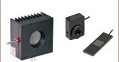
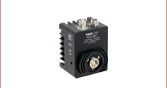
The engraving on the housing is parallel to polarized transmitted light and perpendicular to the orientation of the wires.
Features
- Polarize Light from 3 - 5 µm or 7 - 15 µm
- Extinction Ratio:
- 3 - 5 µm (-IRA): >1000:1
- 7 - 15 µm (-IRC): >10 000:1
- Offered in Four Sizes
- Ø25.0 mm
- 12.5 mm x 12.5 mm
- 25.0 mm x 25.0 mm
- 50.0 mm x 50.0 mm
- Anodized Aluminum Mount with Transmission Axis Indicated
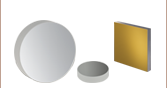
The mounted wire grid polarizers on silicon substrates sold here are designed to provide high extinction over two spectral ranges in the mid-IR: 3 - 5 µm (3333 - 2000 cm-1) or 7 - 15 µm (1429 - 667 cm-1). The 3 - 5 µm versions (denoted by -IRA) offer >1000:1 extinction and >85% average transmission over their specified range, while the 7 - 15 µm versions (denoted by -IRC) offer >10 000:1 extinction and >75% average transmission over their specified range. Wavelength-dependent plots of the transmission are available in the Specs tab. The polarizers are recessed inside Ø25.0 mm, 12.5 mm square, 25.0 mm square, or 50.0 mm square mounts fabricated from anodized aluminum. As shown by the drawings to the right, the mounts are engraved with the polarization axis of the transmitted light.
These MIR polarizers consist of a linearly spaced wire grid pattern that is deposited onto an AR-coated silicon substrate. Silicon was chosen because it offers good transmission in the mid-IR wavelength range. Because the wire grid absorbs and reflects radiation that is polarized parallel to the grid, the polarization of the transmitted radiation is perpendicular to the wires. These polarizers feature a mark on the housing to indicate the transmission axis (see diagrams to the right).
For smooth attenuation over the specified wavelength range and fine control over the output polarization direction, we recommend the Ø25.0 mm versions, which are well suited for use with our family of rotation mounts for Ø1" optics. The 12.5 mm square, 25.0 mm square, and 50.0 mm square versions can be secured in a cylindrical lens mount. Since our cylindrical lens mounts do not provide rotation, the square polarizers are best for applications that only require horizontal or vertical polarization.
The surface of a wire grid polarizer, like any diffraction grating, is extremely delicate. Never touch the surface of the polarizer, and only handle it by the edge. Careful removal of dust by gentle air flow is the only recommended cleaning procedure.
For broadband applications in the MIR, Thorlabs offers holographic wire grid polarizers for the 2 - 30 µm spectral range. In addition, we have wire grid polarizers on glass substrates for the 250 nm - 4 µm spectral range, which help enable the use of a visible alignment beam in a mid-IR experiment. For our complete selection of polarizers, please see the Polarizer Guide tab.
| Item # | WP12LM-IRA | WP25M-IRA | WP25LM-IRA | WP50LM-IRA | WP12LM-IRC | WP25M-IRC | WP25LM-IRC | WP50LM-IRC |
|---|---|---|---|---|---|---|---|---|
| Wavelength Range | 3 - 5 µm (3333 - 2000 cm-1) | 7 - 15 µm (1429 - 667 cm-1) | ||||||
| Extinction Ratioa | >1000:1 Over Entire Wavelength Range | >10 000:1 Over Entire Wavelength Range | ||||||
| Transmissionb | >85% (Average) Over Wavelength Range | >75% (Average) Over Wavelength Range | ||||||
| Housing Size | 12.5 mm x 12.5 mm | Ø25.0 mm | 25.0 mm x 25.0 mm | 50.0 mm x 50.0 mm | 12.5 mm x 12.5 mm | Ø25.0 mm | 25.0 mm x 25.0 mm | 50.0 mm x 50.0 mm |
| Housing Thickness | 5.8 mm | 5.8 mm | 5.8 mm | 5.8 mm | 5.8 mm | 5.8 mm | 5.8 mm | 5.8 mm |
| Clear Aperture | 6.0 mm x 6.0 mmc | Ø19.0 mm | 18.0 mm x 18.0 mmc | 42.0 mm x 42.0 mmc | 6.0 mm x 6.0 mmc | Ø19.0 mm | 18.0 mm x 18.0 mmc | 42.0 mm x 42.0 mmc |
| Transmission Axis Accuracyd |
±2° | |||||||
| Angle of Incidence | ±20° | |||||||
| Distance Between Wires |
144 nm | |||||||
| Wire Thickness | 65 nm | |||||||
| Thermal Expansion | 2.6 x 10⁻⁶ per °C | |||||||
| Substrate | AR-Coated Silicon | |||||||
Engraving is Parallel to Transmitted Light Polarization
Transmission of -IRA Polarizers
Click to Enlarge
Excel Spreadsheet Containing Raw Data
Transmission of 3 - 5 µm Polarizers
Click to Enlarge
Excel Spreadsheet Containing Raw Data
Extended-Range Transmission of 3 - 5 µm Polarizers
The shaded region in this graph denotes the range over which these polarizers provide >1000:1 extinction.
Transmission of -IRC Polarizers
Click to Enlarge
Excel Spreadsheet Containing Raw Data
Transmission of 7 - 15 µm Polarizers
Click to Enlarge
Excel Spreadsheet Containing Raw Data
Extended-Range Transmission of 7 - 15 µm Polarizers
The shaded region in this graph denotes the range over which these polarizers provide >10 000:1 extinction.
| Posted Comments: | |
bob henderson
(posted 2023-11-14 08:35:52.553) is this polariser suitable for use with the MLQD4500 laser from the point of view of laser damage threshold? Ivan Zorin
(posted 2023-08-11 08:51:33.333) Dear Madam or Sir,
I have ordered WP12LM-IRC. What solution would you suggest to have the possibility to rotate the polarizer?
Bests,
Ivan cdolbashian
(posted 2023-08-16 12:26:04.0) Thank you for reaching out to us with this inquiry! As we do not have a specific 1/2" square optic rotation mount, I think the best solution would be a combination of CYCPA and CPU1. I have reached out to you directly to discuss this. 杰 郭
(posted 2023-07-03 15:08:07.713) What is the test method of extinction ratio and transmittance of WP25M-IRC? I hope I can confirm that the extinction ratio and transmittance indicators in the specification are accurate according to the test method cdolbashian
(posted 2023-07-13 01:08:02.0) Thank you for reaching out to us with this inquiry! I have reached out to you directly to recommend such a configuration for a test setup which would facilitate the validation of such parameters which we provide in the specification tab. Ron Govoro
(posted 2021-07-01 10:41:18.923) Regarding the MIR polarizers on Si (e.g. WP25M-IRC) It would be helpful to have either data or estimates of damage levels for these optics listed on the website in the spec tab. I know this info is on other manufacturers docs. It may not seem necessary as MIR lasers are generally power limited well below the actual damage level of 10 kW/cm2 (except for 10.6 um CO2 lasers), but it would still serve to tell the customer what a safe working level is.
Thank You!
Ron Ron Govoro
(posted 2021-06-08 11:33:36.11) Hello,
I'd like to speak with a technical expert on MIR Si polarizers, the 7-15 um version. I need to understand damage level for this optic before recommending it to a customer we make a 9713 nm laser for. Hoping to answer the following;
-max level of optical power on optic in CW mode?
-any info on curve for power vs. lifetime?
Please contact me at rgovoro@thorlabs.com, 240-456-7241 or cell 301-357-1337.
Thank You!
Ron Poul Petersen
(posted 2021-02-23 15:40:55.813) Could you tell me what the thickness of the silicon substrate is?
Would it be possible to make a version on a very thin silicon substrate? Say 300 micron?
Thank you
Poul YLohia
(posted 2021-02-24 10:02:42.0) Hello, the substrate thickness of the WP12LM-IRA is 0.675 mm. Custom optics can be requested by clicking on the "Request Quote" button above or by emailing your local Thorlabs Tech Support Team (in your case europe@thorlabs.com). We will discuss the possibility of offering this customization directly. Alex Sabella
(posted 2020-07-28 02:26:50.743) Hi,
Do you have CW damage thresholds for the MIR polarisers on silicon (e.g WP25LM-IRA) or the holographic wire grid polariser (e.g. WP25H-B).
Thank you,
Alex YLohia
(posted 2020-07-30 02:38:12.0) Hello Alex, thank you for contacting Thorlabs. As per our direct discussion, your beam parameters of 4.8um 2W (2 mm x 3 mm) will be fine to use with the WP25LM-IRA. Martin Svoren
(posted 2020-05-27 03:22:21.777) Hey Thorlabs,
we are missing threshold damage information. could you tell us?
Thank you and best regards
Martin YLohia
(posted 2020-07-14 02:03:30.0) Hello Martin, thank you for contacting Thorlabs. Could you please tell us your beam parameters (Wavelength, average power, peak power, pulse width, and repetition rate)? I had reached out to you at the time of your posting but I never heard back. Please email us at techsupport@thorlabs.com if you have further questions. georg.ramer
(posted 2018-10-11 18:06:16.153) What is the extinction ratio of the IRC wiregrid polarizers outside the specified transmission range of 7 to 15 um? YLohia
(posted 2018-10-15 10:34:32.0) Hello, thank you for contacting Thorlabs. The transmission in the 2-16um extended range is given in the Specs tab. hasal
(posted 2014-12-08 12:43:40.217) Hello, can you tell me which value of extinction ration is related to the WP12LM-IRA? Do you offer all of the listed types in two variations with 1:1000 and 1:10 000? Thanks for explanation. myanakas
(posted 2014-12-08 08:54:22.0) Response from Mike at Thorlabs: Thank you for your feedback. The extinction ratio for the WP12LM-IRA is >1000:1. This can be found in the table on the "Specs" tab or on the support drawing, which can be found by clicking on the red "Decs" icon next to the part number (http://www.thorlabs.de/thorcat/TTN/WP12LM-IRA-AutoCADPDF.pdf). Part numbers ending in -IRA have an extinction ration of >1000:1 and part numbers ending in -IRC have an extinction ratio of >10000:1. We will work to make this more clear on the webpage. zachary.flom
(posted 2014-09-13 21:50:45.263) Will WP25M-IRA pass a decent fraction of light at 650nm? I just want to make sure our pointing lasers will still be visible after passing through two or three of these (assuming the pointing laser is correctly polarized to pass through). Thanks. |
Polarizer Selection Guide
Thorlabs offers a diverse range of polarizers, including wire grid, film, calcite, alpha-BBO, rutile, and beamsplitting polarizers. Collectively, our line of wire grid polarizers offers coverage from the visible range to the beginning of the Far-IR range. Our nanoparticle linear film polarizers provide extinction ratios as high as 100 000:1. Alternatively, our other film polarizers offer an affordable solution for polarizing light from the visible to the Near-IR. Next, our beamsplitting polarizers allow for use of the reflected beam, as well as the more completely polarized transmitted beam. Finally, our alpha-BBO (UV), calcite (visible to Near-IR), rutile (Near-IR to Mid-IR), and yttrium orthovanadate (YVO4) (Near-IR to Mid-IR) polarizers each offer an exceptional extinction ratio of 100 000:1 within their respective wavelength ranges.
To explore the available types, wavelength ranges, extinction ratios, transmission, and available sizes for each polarizer category, click More [+] in the appropriate row below.
| Wire Grid Polarizers |
|---|
| Film Polarizers |
|---|


| Beamsplitting Polarizers |
|---|


| alpha-BBO Polarizers |
|---|
| Calcite Polarizers |
|---|
| Quartz Polarizers |
|---|
| Magnesium Fluoride Polarizers |
|---|
| Yttrium Orthovanadate (YVO4) Polarizers |
|---|
| Rutile Polarizers |
|---|