 Products Home
Laser Viewing Cards
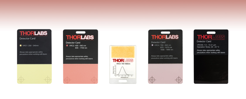
- Detect Wavelengths from UV to MIR
- Handheld Photosensitive and Liquid Crystal Cards
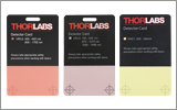
VRC1
VRC2
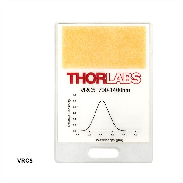
VRC5
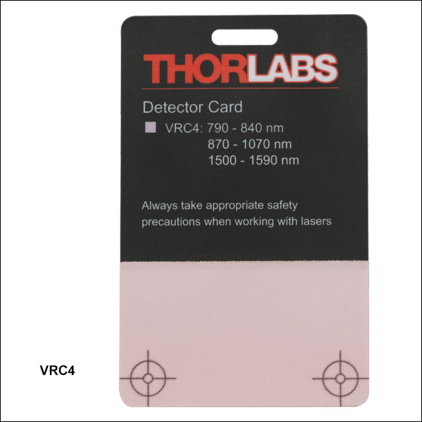
VRC4
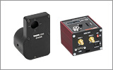
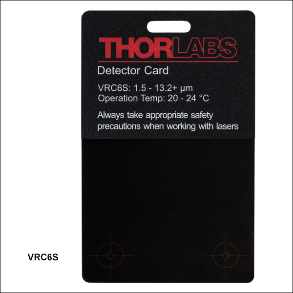
VRC6S
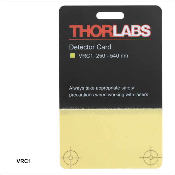
250 to 540 nm
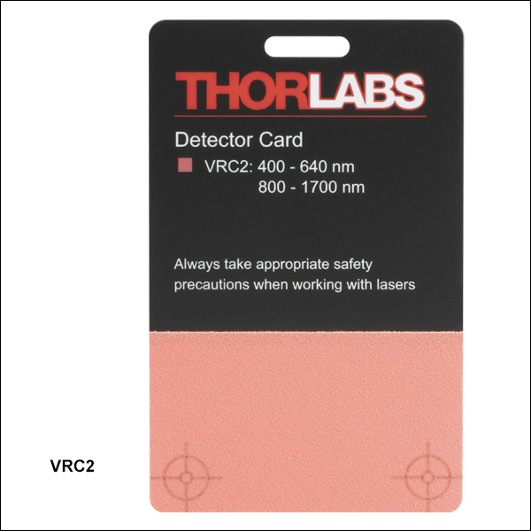
400 to 640 nm
and 800 to 1700 nm
700 to 1400 nm
790 to 840 nm,
870 to 1070 nm,
and 1500 to 1590 nm
1.5 to >13.2 µm


Please Wait
Features
- Detector Cards for UV, Visible, NIR, or MIR Wavelength Ranges
- Detect Radiation as Low as 1 nW/cm2
- Absorption Wavelength Range(s) or Sensitivity Curve Printed on Card
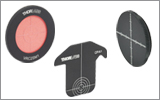
Thorlabs' detector cards include light-sensitive active areas that enable the location of a UV, visible, near-IR (NIR), or mid-IR (MIR) laser beam and its focal point. To facilitate their use during alignment procedures, every card, except Item # VRC5, has a detection region that extends all the way to the edge of the card and two engraved reticles for use in laser beam collimation.
Please note that these detector cards are not intended to be used as laser beam blocks, and appropriate safety measures should be taken when working with laser beams. See the Laser Safety tab for details.
Click to Enlarge
Wavelength Absorption from 400 - 640 nm & 800 - 1700 nm
Wavelength Emission from ~580 - 750 nm

Click to Enlarge
Wavelength Absorption from 790 - 840 nm & 870 - 1070 nm & 1500 - 1590 nm
Wavelength Emission from ~520 - 580 nm

Insights into Aligning a Laser Beam
When installing a laser in an optical setup, it is good practice to start by leveling and orienting its beam so that it travels along a well-defined path. When the beam is prepared this way, not only is it easier to then divert the beam and route it through the optical elements in the system, but the results provided by tuning the system's alignment are more predictable and repeatable. The following sections describe how to:
- Level and Align the Laser Beam's Pointing Angle
- Divert the Beam and Align it to Follow a Desired Path
Click here for more Insights about lab practices and equipment.
Level and Align the Laser Beam's Pointing Angle
0:00 - Introduction
1:25 - Level and Align the Laser Beam's Pointing Angle
4:09 - Divert the Beam and Align it to Follow a Desired Path
Click to Enlarge
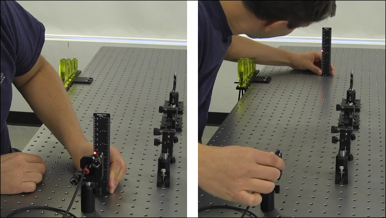
Figure 2: The beam can be aligned to travel parallel to a line of tapped holes in the optical table. The yaw adjustment on the kinematic mount adjusts the beam angle, so that the beam remains incident on the ruler's vertical reference line as the ruler slides along the line of tapped holes.
Click to Enlarge
Figure 1: Leveling the beam path with respect to the surface of an optical table requires using the pitch adjustment on the kinematic laser mount (Figure 2). The beam is parallel to the table's surface when measurements of the beam height near to (left) and far from (right) the laser's front face are equal.
Pitch (tip) and yaw (tilt) adjustments provided by a kinematic mount can be used to make fine corrections to a laser beam's angular orientation or pointing angle. This angular tuning capability is convenient when aligning a collimated laser beam to be level with respect to a reference plane, such as the surface of an optical table, and when aligning with respect to a particular direction in that plane, such as along a line of tapped holes in the table.
Before Using the Mount's Adjusters
First, rotate each adjuster on the kinematic mount to the middle of its travel range. This reduces the risk of running out of adjustment range, and the positioning stability is frequently better when at the center of an adjuster's travel range.
Then, make coarse corrections to the laser's height, position, and orientation. This can be done by adjusting the optomechanical components, such as a post and post holder, supporting the laser. Ensure all locking screws are tightened after the adjustments are complete.
Level the Beam Parallel to the Table's Surface
Leveling the laser beam is an iterative process that requires an alignment tool and the fine control provided by the mount's pitch adjuster.
Begin each iteration by measuring the height of the beam close to and far from the laser (Figure 1). A larger distance between the two measurements increases accuracy. If the beam height at the two locations differs, place the ruler in the more distant position. Adjust the pitch on the kinematic mount until the beam height at that location matches the height measured close to the laser. Iterate until the beam height at both positions is the same.
More than one iteration is necessary, because adjusting the pitch of the laser mount adjusts the height of the laser emitter. In the video for example, the beam height close to the laser was initially 82 mm, but it increased to 83 mm after the pitch was adjusted during the first iteration.
If the leveled beam is at an inconvenient height, the optomechanical components supporting the laser can be adjusted to change its height. Alternatively, two steering mirrors can be placed after the laser and aligned using a different procedure, which is detailed in the section. Steering mirrors are particularly useful for adjusting beam height and orientation of a fixed laser.
Orient the Beam Along a Row of Tapped Holes
Aligning the beam parallel to a row of tapped holes in the table is another iterative process, which requires an alignment tool and tuning of the mount's yaw adjuster.
The alignment tool is needed to translate the reference line provided by the tapped holes into the plane of the laser beam. The ruler can serve as this tool, when an edge on the ruler's base is aligned with the edges of the tapped holes that define the line (Figure 2).
The relative position of the beam with respect to the reference line on the table can be evaluated by judging the distance between the laser spot and vertical reference feature on the ruler. Vertical features on this ruler include its edges, as well as the columns formed by different-length rulings. If these features are not sufficient and rulings are required, a horizontally oriented ruler can be attached using a BHMA1 mounting bracket.
In the video, when the ruler was aligned to the tapped holes and positioned close to the laser, the beam's edge and the ends of the 1 mm rulings coincided. When the ruler was moved to a farther point on the reference line, the beam's position on the ruler was horizontally shifted. With the ruler at that distant position, the yaw adjustment on the mount was tuned until the beam's edge again coincided with the 1 mm rulings. The ruler was then moved closer to the laser to observe the effect of adjusting the mount on the beam's position. This was iterated as necessary.
Divert the Beam and Align it to Follow a Desired Path
The first steering mirror reflects the beam along a line that crosses the new beam path. A second steering mirror is needed to level the beam and align it along the new path. The procedure of aligning a laser beam with two steering mirrors is sometimes described as walking the beam, and the result can be referred to as a folded beam path. In the example shown in the video above, two irises are used to align the beam to the new path, which is parallel to the surface of the optical table and follows a row of tapped holes.
Click to Enlarge
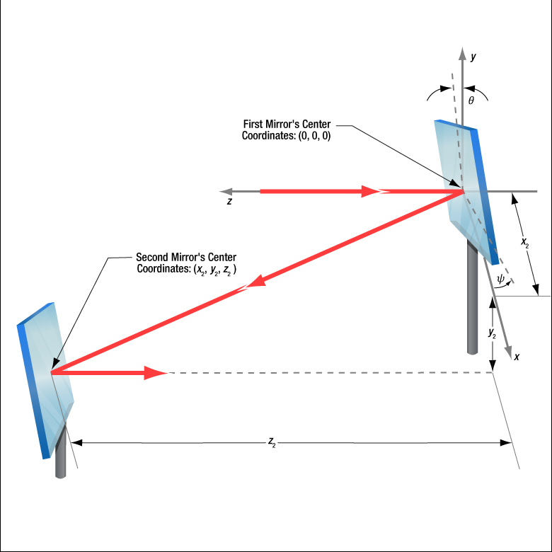
Figure 3: The beam reflected from Mirror 1 will be incident on Mirror 2, if Mirror 1 is rotated around the x- and y-axes by angles θ and ψ, respectively. Both angles affect each coordinate (x2 , y2 , z2 ) of Mirror 2's center. Mirror 1's rotation around the x-axis is limited by the travel range of the mount's pitch (tip) adjuster, which limits Mirror 2's position and height options.
Click to Enlarge
Figure 5: The adjusters on the second kinematic mirror are used to align the beam on the second iris.
Click to Enlarge
Figure 4: The adjusters on the first kinematic mirror mount are tuned to position the laser spot on the aperture of the first iris.
Setting the Heights of the Mirrors
The center of the first mirror should match the height of the input beam path, since the first mirror diverts the beam from this path and relays it to a point on the second mirror. The center of the second mirror should be set at the height of the new beam path.
Iris Setup
The new beam path is defined by the irises, which in the video have matching heights to ensure the path is level with respect to the surface of the table. A ruler or calipers can be used to set the height of the irises in their mounts with modest precision.
When an iris is closed, its aperture may not be perfectly centered. Because of this, switching the side of the iris that faces the beam can cause the position of the aperture to shift. It is good practice to choose one side of the iris to face the beam and then maintain that orientation during setup and use.
Component Placement and Coarse Alignment
Start by rotating the adjusters on both mirrors to the middle of their travel ranges. Place the first mirror in the input beam path, and determine a position for the second mirror in the new beam path (Figure 3). The options are notably restricted by the travel range of the first mirror mount's pitch (tip) actuator, since it limits the mirror's rotation (θ ) around its x-axis. In addition to the pitch, the yaw (tilt) of the first mirror must also be considered when choosing a position
After placing the second mirror on the new beam path, position both irises after the second mirror on the desired beam path. Locate the first iris near the second mirror and the second iris as far away as possible.
While maintaining the two mirrors' heights and without touching the yaw adjusters, rotate the first mirror to direct the beam towards the second mirror. Adjust the pitch adjuster on the first mirror to place the laser spot near the center of the second mirror. Then, rotate the second mirror to direct the beam roughly along the new beam path.
First Hit a Point on the Path, then Orient
The first mirror is used to steer the beam to the point on the second mirror that is in line with the new beam path. To do this, tune the first mirror's adjusters while watching the position of the laser spot on the first iris (Figure 4). The first step is complete when the laser spot is centered on the iris' aperture.
The second mirror is used to steer the beam into alignment with the new beam path. Tune the adjusters on the second mirror to move the laser spot over the second iris' aperture (Figure 5). The pitch adjuster levels the beam, and the yaw adjuster shifts it laterally. If the laser spot disappears from the second iris, it is because the laser spot on the second mirror has moved away from the new beam path.
Tune the first mirror's adjusters to reposition the beam on the second mirror so that the laser spot is centered on the first iris' aperture. Resume tuning the adjusters on the second mirror to direct the laser spot over the aperture on the second iris. Iterate until the laser beam passes directly through the center of both irises, as shown in the video. If any adjuster reaches, or approaches, a limit of its travel range, one or both mirrors should be repositioned and the alignment process repeated.
If a yaw axis adjuster has approached a limit, note the required direction of the reflected beam and then rotate the yaw adjuster to the center of its travel range. Turn the mirror in its mount until the direction of the reflected beam is approximately correct. If the mirror cannot be rotated, reposition one or both mirrors to direct the beam roughly along the desired path. Repeat the alignment procedure to finely tune the beam's orientation.
If a pitch axis adjuster has approached a limit, either increase the two mirrors' separation or reduce the height difference between the new and incident beam paths. Both options will result in the pitch adjuster being positioned closer to the center of its travel range after the alignment procedure is repeated.
Laser Safety and Classification
Safe practices and proper usage of safety equipment should be taken into consideration when operating lasers. The eye is susceptible to injury, even from very low levels of laser light. Thorlabs offers a range of laser safety accessories that can be used to reduce the risk of accidents or injuries. Laser emission in the visible and near infrared spectral ranges has the greatest potential for retinal injury, as the cornea and lens are transparent to those wavelengths, and the lens can focus the laser energy onto the retina.
 |
 |
 |
 |
 |
 |
 |
 |
 |
Safe Practices and Light Safety Accessories
- Laser safety eyewear must be worn whenever working with Class 3 or 4 lasers.
- Regardless of laser class, Thorlabs recommends the use of laser safety eyewear whenever working with laser beams with non-negligible powers, since metallic tools such as screwdrivers can accidentally redirect a beam.
- Laser goggles designed for specific wavelengths should be clearly available near laser setups to protect the wearer from unintentional laser reflections.
- Goggles are marked with the wavelength range over which protection is afforded and the minimum optical density within that range.
- Laser Safety Curtains and Laser Safety Fabric shield other parts of the lab from high energy lasers.
- Blackout Materials can prevent direct or reflected light from leaving the experimental setup area.
- Thorlabs' Enclosure Systems can be used to contain optical setups to isolate or minimize laser hazards.
- A fiber-pigtailed laser should always be turned off before connecting it to or disconnecting it from another fiber, especially when the laser is at power levels above 10 mW.
- All beams should be terminated at the edge of the table, and laboratory doors should be closed whenever a laser is in use.
- Do not place laser beams at eye level.
- Carry out experiments on an optical table such that all laser beams travel horizontally.
- Remove unnecessary reflective items such as reflective jewelry (e.g., rings, watches, etc.) while working near the beam path.
- Be aware that lenses and other optical devices may reflect a portion of the incident beam from the front or rear surface.
- Operate a laser at the minimum power necessary for any operation.
- If possible, reduce the output power of a laser during alignment procedures.
- Use beam shutters and filters to reduce the beam power.
- Post appropriate warning signs or labels near laser setups or rooms.
- Use a laser sign with a lightbox if operating Class 3R or 4 lasers (i.e., lasers requiring the use of a safety interlock).
- Do not use Laser Viewing Cards in place of a proper Beam Trap.
Laser Classification
Lasers are categorized into different classes according to their ability to cause eye and other damage. The International Electrotechnical Commission (IEC) is a global organization that prepares and publishes international standards for all electrical, electronic, and related technologies. The IEC document 60825-1 outlines the safety of laser products. A description of each class of laser is given below:
| Class | Description | Warning Label |
|---|---|---|
| 1 | This class of laser is safe under all conditions of normal use, including use with optical instruments for intrabeam viewing. Lasers in this class do not emit radiation at levels that may cause injury during normal operation, and therefore the maximum permissible exposure (MPE) cannot be exceeded. Class 1 lasers can also include enclosed, high-power lasers where exposure to the radiation is not possible without opening or shutting down the laser. |  |
| 1M | Class 1M lasers are safe except when used in conjunction with optical components such as telescopes and microscopes. Lasers belonging to this class emit large-diameter or divergent beams, and the MPE cannot normally be exceeded unless focusing or imaging optics are used to narrow the beam. However, if the beam is refocused, the hazard may be increased and the class may be changed accordingly. |  |
| 2 | Class 2 lasers, which are limited to 1 mW of visible continuous-wave radiation, are safe because the blink reflex will limit the exposure in the eye to 0.25 seconds. This category only applies to visible radiation (400 - 700 nm). |  |
| 2M | Because of the blink reflex, this class of laser is classified as safe as long as the beam is not viewed through optical instruments. This laser class also applies to larger-diameter or diverging laser beams. |  |
| 3R | Class 3R lasers produce visible and invisible light that is hazardous under direct and specular-reflection viewing conditions. Eye injuries may occur if you directly view the beam, especially when using optical instruments. Lasers in this class are considered safe as long as they are handled with restricted beam viewing. The MPE can be exceeded with this class of laser; however, this presents a low risk level to injury. Visible, continuous-wave lasers in this class are limited to 5 mW of output power. |  |
| 3B | Class 3B lasers are hazardous to the eye if exposed directly. Diffuse reflections are usually not harmful, but may be when using higher-power Class 3B lasers. Safe handling of devices in this class includes wearing protective eyewear where direct viewing of the laser beam may occur. Lasers of this class must be equipped with a key switch and a safety interlock; moreover, laser safety signs should be used, such that the laser cannot be used without the safety light turning on. Laser products with power output near the upper range of Class 3B may also cause skin burns. |  |
| 4 | This class of laser may cause damage to the skin, and also to the eye, even from the viewing of diffuse reflections. These hazards may also apply to indirect or non-specular reflections of the beam, even from apparently matte surfaces. Great care must be taken when handling these lasers. They also represent a fire risk, because they may ignite combustible material. Class 4 lasers must be equipped with a key switch and a safety interlock. |  |
| All class 2 lasers (and higher) must display, in addition to the corresponding sign above, this triangular warning sign. |  |
|
| Posted Comments: | |
ZW Long
(posted 2024-09-14 01:59:58.177) What is the minimum detectable power density of VRC6S at around 3.3um? Thanks. Paul Griffin
(posted 2024-08-05 10:14:25.54) Is it possible to have the VRC5 card with a matte finish? The laminated cover on the VRC5 cards creates an issue with stray reflections. Our lab had a recent incident where a researcher had received a laser flash due to this reflection, although, thankfully, at a below-MPE level.
I am primarily using 780-nm lasers and have found that the matte-finished cards do not have good visibility in this range.
We cover the issue of reflectivity of the cards in our laser safety training. However, accidents still happen. Our safety team are currently considering banning of the laminated cards, which would create a serious issue for our work. jpolaris
(posted 2024-08-05 07:02:05.0) Thank you for contacting Thorlabs. I am glad to hear that the researcher was unharmed. Please remember to wear laser safety glasses. Requests for customizations can be made by emailing us at techsupport@thorlabs.com. I have reached out to you directly to discuss the feasibility of this customization. Matthias Kübel
(posted 2024-06-13 16:31:03.007) Dear product team,
I would like to propose a new product, namely a detector card that is a merger between the VRC2 and VRC4 cards For example, the VRC2 coating (red) could be deposited on one side of the card, the VRC4 coating (white) on the other side.
In our lab, we use both cards to view our near-infrared laser beam centered at 1030 nm. In many alignment tasks we switch back and forth between the two cards. If one had a single card with both coatings, it could make our work more efficient and pleasant.
For more background information:
The VRC4 is generally the prefered detector card as it provides great visibility (green light on a white detector card) and does not depelete. For a weak beam, however, the VRC 2 is preferred as it is much more sensitive. However, it depletes rapidly when the beam is rather intense.
Best regards
Matthias cdolbashian
(posted 2024-06-21 03:51:09.0) Thank you for reaching out to us with this request! I will inquire internally regarding the feasibility of making various double-sided detector cards. In the meantime, perhaps an alternative solution can be reached simply by adhering your two cards back-to-back. If you are worried about transmission between them, a simply sheet of aluminum foil can be included between cards. I have contacted directly to discuss this further. Hung Cheng
(posted 2024-03-29 21:38:39.367) Subject: Inquiry Regarding Composition of Layers in NIR Card Reflectance Signal Measurement
Dear Thorlabs,
I am currently conducting research on SD-OCT and have recently been utilizing your company's product for measurements. Upon analysis, it appears that the reflected signal comprises approximately four or five layers. I am reaching out to kindly request information on the composition of these layers from top to bottom within the NIR sensitive region.
Your assistance in providing an overview of the layers included in this profile would be greatly appreciated.
Thank you in advance for your attention to this matter.
Warm regards ksosnowski
(posted 2024-04-22 02:05:42.0) Hello Hung, thanks for reaching out to Thorlabs. The phosphor layer is sandwiched by plastic coating layers, with an adhesive layer connecting this to the backing card. We also use the VRC series cards as alignment tools with our OCT systems as the layer structure provides an easy visual reference for whether the system is correctly connected and set up, and help visualize the scan beam at the same time. I have reached out directly to discuss this application in further detail. 康 孙
(posted 2024-01-29 16:48:49.97) 请问咱们的激光观察卡在不同的角度上观察这个入射的光斑的位置时会有明显的差别,请问这个现象该怎么解释?又怎么避免呢?谢谢! ksosnowski
(posted 2024-01-29 04:33:36.0) Hello, thanks for reaching out to Thorlabs. The surface of the VRC series viewers has a matte finish so should act like a diffuse absorber and be fairly independent of angle of incidence. However at higher angle of incidence with the input beam, the projection of the beam across the card is further spread out. Since a minimum power per area is required to make the spot visible to the human eye, the lower power density at higher angles may make this more difficult to view. I have reached out directly to discuss this application further. Benjamin Feldtman
(posted 2022-11-06 17:16:42.933) Hi Thor team,
We use the VCR4 cards extensively, but have often wished the active area was larger. Is it possible to order cards in a larger size without the engraved circles, or sheets of the stick-on active material? ksosnowski
(posted 2022-11-07 02:11:05.0) Hello Benjamin, thanks for reaching out to Thorlabs. We are able to provide larger sizes of these laser viewing materials, which come with an adhesive backing. Requests like this are best directed to techsales@thorlabs.com to confirm size and quantity requirements before we can provide a quote. Joonhak Park
(posted 2022-10-06 11:47:02.95) Dear Sir or Madam,
I am an optical engineer here, Healux which specializes in the medical industry in Korea.
I recently bought the VRC6H card for detecting a wavelength of 2940nm.
However, it was detected even at a wavelength of 1064nm. The energy was about 200mJ at 1ms pulse width and I used an ND filter of 1% to lower the intensity.
Here's a question. In this case, can a laser beam of 1064nm be detected by your VRC6H card? or is it actually a mixture of 2940nm of light?
I am looking forward to your response.
Best regards,
Joonhak cdolbashian
(posted 2022-10-24 09:45:10.0) Thank you for contacting Thorlabs. VRC6S and VRC6H is based on thermochromic liquid crystal which, thorough color change, visualize the temperature change on the surface of the viewing card when a laser beam lands on it. Thus it actual response to all wavelength (other than UV since UV may damage the liquid crystal). However its response is much slower and sensitivity lower than that of a phosphorous viewing card like VRC2 or VRC4. Therefore, those phosphorous viewing card over the VRC6S or VRC6H are recommended for laser viewing in the NIR range. user
(posted 2022-09-15 15:48:56.127) This is a great IR card, and works significantly better at the wavelengths I use than the other cards. However, the best one I have is one where the backing was carefully peeled off such that the card just has the front plastic and the fluorescing medium. It's nice because you can much more easily overlap counterpropagating beams. The card has also been cut down so that the edge of the fluorescing medium is at the edge of the card. I'm wondering if you might consider selling IR cards like this as it's quite difficult to remove the back paper without damaging the card. ksosnowski
(posted 2022-09-15 07:18:44.0) Thanks for reaching out to Thorlabs. We appreciate this insight and I am adding this to our forum for internal development so we can consider this type of feature in the future. I have reached out directly to further discuss this application. Shahad AL-Gburi
(posted 2022-06-04 14:52:11.957) Dear Sir or Madam,
I am a master student at HAWK Göttingen in the field of laser and plasma technology.
Currently I am working on my master thesis and for this I am supposed to evaluate the TruDiode 151 laser. The wavelength range is between 920nm-970nm and the power density is 10 w/cm2.
I want to visualize the laser spot and found your product (IR-Detector card) on the internet for this purpose, regarding IR-Detector card VRC4 I have the following questions:
1. can they withstand such high power?
2. can they display the laser dot visibly?
I would be grateful if you could give me more information about it.
I will be glad to answer any other questions you may have :)
Kind regards
Shahad Al-Gburi
M.Sc. Laser and Plasma Technology
Faculty of Engineering and Health Shahad AL-Gburi
(posted 2022-06-04 14:50:31.903) Dear Sir or Madam,
I am a master student at HAWK Göttingen in the field of laser and plasma technology.
Currently I am working on my master thesis and for this I am supposed to evaluate the TruDiode 151 laser. The wavelength range is between 920nm-970nm and the power density is 10 w/cm2.
I want to visualize the laser spot and found your product (IR-Detector card) on the internet for this purpose, regarding IR-Detector card VRC4 I have the following questions:
1. can they withstand such high power?
2. can they display the laser dot visibly?
I would be grateful if you could give me more information about it.
I will be glad to answer any other questions you may have :)
Yours sincerely
Shahad Al-Gburi
M.Sc. Laser and Plasma Technology
Faculty of Engineering and Health ksosnowski
(posted 2022-06-20 09:20:36.0) Thanks for reaching out to Thorlabs. Our Laser Viewing Cards are not intended for such high power density applications, and while the minimum visibility generally depends on the ambient light level, this power level is well above those thresholds. We have not performed CW damage testing on these, however customers have reported damage in IR around 700mW/cm^2 for similar cards with small beams. In some cases customers have also reported slightly higher, and it could vary some with beam size. I would recommend attenuating the beam to <300mW/cm^2 or less to test with, and by starting with a corner of the card you can slowly raise the power to observe the damage threshold in your exact setup. I've reached out directly to discuss your application further. Philipp K.
(posted 2021-11-17 03:24:01.873) Hi Thorlabs,
you once sold a version of the MIR viewing crd that was backed on a metal sheet. It was very useful for slightly higher powers and for faster recovery. My stock of these cards is slowly decaying - Is there a reason you dont offer them anymore? Will they be avalable again?
Best YLohia
(posted 2021-11-23 02:04:39.0) Thank you for contacting Thorlabs. For the updated VRC6 series, we optimized the liquid crystal material and removed the aluminum backing to improve the sensitivity of the card. We have reached out directly to discuss this further. user
(posted 2021-02-24 14:46:59.81) How long the VRC2 has to be charged in visible light before use? asundararaj
(posted 2021-02-24 03:33:59.0) Thank you for contacting Thorlabs. While we do not specify a time for charging, it typically takes a couple second to charge. To look at a beam without interruption, we recommend moving the card to move the position of the incident light spot around the active region to maintain the intensity of the excited emission. Thomas Hadnich
(posted 2020-01-30 09:12:51.613) Can you please inform me about the customs tariff number of those detector cards. YLohia
(posted 2020-01-31 09:39:18.0) Hello, thank you for contacting Thorlabs. The HTS code for the VRC5 detector card is 9027508060. Lucile SANCHEZ
(posted 2020-01-14 18:35:36.54) Hello,
could you make a card with a non reflective plastic like the VRC serie except the VRC5 but for the 780 nm?
It is quite dangerous to see the reflexion when you have two beams to consider and one that is red like 630nm and an IR beam and the red can actually being reflected on the card and damage your eyes...
Thanks a lot,
Best regards,
Lucile YLohia
(posted 2020-01-15 09:13:14.0) Hello Lucile, thank you for your feedback. I have posted your suggestion on our internal engineering and design forum for further consideration as a future update. user
(posted 2019-04-16 16:54:49.96) The plastic rim around the card is annoying. It would be ideal to have a similar card with the detector region of the card extending to the edges of the card. YLohia
(posted 2019-04-17 08:54:15.0) Hello, thank you for your feedback and my apologies for the issues caused by the borders of this card. We will certainly keep this in mind when designing the next iteration of this card. I have posted your feedback in our internal engineering forum for further consideration. dsteil
(posted 2018-09-17 13:56:41.477) Hi,
would it be possible to put the IR or UV-active materials onto a metal substrate? We do burn this cards quite often due to high average power of our femtosecond fiber amplifiers (pulse energy is not the problem), but mostly it seems that the plastic is in fact the first one to go not the coating.
Best
Daniel nbayconich
(posted 2018-09-21 09:57:14.0) Thank you for contacting Thorlabs. We can provide the fluorescent material alone on a self-adhesive backing which could then be placed on metallic surface if needed. I'll reach out to you directly to discuss our custom capabilities. felix.attila.farkas
(posted 2018-02-08 15:49:07.54) Hello Thorlabs,
I am interested in a laser protection system for some of our products categories.
Is there a laser exposure indicator foil that is not reversible?
If the product was exposed at a certain wavelength range then the foil will change permanently the color and remain like that.
Could you please give me a feedback for this?
Thanks you!
Attila nbayconich
(posted 2018-03-30 03:17:02.0) Thank you for contacting Thorlabs. It sounds like you are describing laser burn paper which can be used as an indicator of a high intensity laser. At the moment we do not supply products similar to burn paper and we have not tested our laser viewing detection cards in the same application. These laser viewing cards are generally used for just locating the position of an IR or UV source but are not intended to be used in the same application as burn paper. I will reach out to you directly to discuss your application kedves
(posted 2017-05-23 14:08:28.58) Dear Thorlabs, which laser viewing card can you recommend for 780 nm? VCR5's absorption band seems to cover 780 nm, but it has a smaller sensitive area and a shiny surface which are not advantageous. How about VCR2 and VCR4? Is there any experience how sensitive these are at 780 nm? Thanks nbayconich
(posted 2017-07-10 11:50:46.0) Thank you for contacting Thorlabs. We recommend using the VRC5 for 780nm. Our VRC2 & VRC4 IR cards do not cover 780nm in their absorption range. I will reach out to you directly to discuss the VRC2 & VRC4's sensitivity. user
(posted 2016-04-05 00:31:49.21) Can we have these in the form of alignment disks, such as the VRC2D1's which can be mounted on alignment targets? thanks! besembeson
(posted 2016-04-05 11:30:55.0) Response from Bweh at Thorlabs USA: Thanks for your feedback. We will look into expanding these alignment disks to include the VRC1 as you suggested. berkdiler
(posted 2016-03-23 16:31:40.833) I work with a wide range of IR wavelengths. I see online that there are materials to view IR without recharging. I do have your florescent viewers however since they bleach extremely fast the SM1 mounted ones are useless (since they are stationary). I see that the material VR4 only works for a short range of wavelengths however there seems to be a similar material http://www.zap-it.com/products/view-it-ir-laser-spot-targets on this website that works with a much broader wavelength. Another material I found online is http://www.sintecoptronics.com/irdetector.asp, which is a doubling ceramic.
Overall I would appreciate a lot a broadband NIR card (800-1700) without bleaching and the material to make one appears to exist. besembeson
(posted 2016-03-24 01:54:42.0) Response from Bweh at Thorlabs USA: Thanks very much for your very valuable feedback. We are going to review our viewing card offerings. ryanh
(posted 2016-02-22 04:21:17.59) Is the VRC6 detector card suitable for beam alignment of a 200W CO2 laser with a power density of approximately 200W/CM2 or will it damage the card? The laser will only be firing 1 pulse with an on time of around 50uS. Thanks. besembeson
(posted 2016-03-03 02:05:37.0) Response from Bweh at Thorlabs USA: That laser power is significantly much higher than what we have tested the card with. These are generally not recommended for high power applications. I will contact you regarding testing this. drakem
(posted 2016-02-17 15:40:48.323) It would be very helpful if the card's destructive threshold laser intensity were included. I burnt a hole in it the first time I used it. besembeson
(posted 2016-03-03 01:31:27.0) Response from Bweh at Thorlabs USA. Thanks for your feedback. These are generally not recommended for high power applications. We will look into adding some notes on our website for recommended high power levels. I will contact you regarding your damaged card. yehonatan.gilead
(posted 2015-05-21 13:07:12.287) Hello,
I can't seem to find the dimensions of the painted reticles. perhaps you could post the diameters of the small and large circles, as well as the length of the lines? jlow
(posted 2015-05-21 11:36:15.0) Response from Jeremy at Thorlabs: The line width is around 0.004". The inner circle is about Ø0.063" and the outer circle is about Ø0.288". The length of the cross is about 0.512" (same for both vertical and horizontal lines) maxl
(posted 2014-12-18 16:31:41.427) Can you offer IR Card Damage Threshold spec
Thanks for your help!
Looking forward to hearing from you soon! besembeson
(posted 2014-12-18 04:25:58.0) Response from Bweh at Thorlabs: We don't have damage threshold specification yet for these. I will contact you by email to determine if this can still be suitable for you. user
(posted 2014-07-22 17:21:31.48) Can I cut one of these cards into a small piece that would fit my sample holder, or would that destroy it? jlow
(posted 2014-08-01 11:09:06.0) Response from Jeremy at Thorlabs: These can be cut into smaller pieces. Eddie.wu
(posted 2014-07-14 16:38:22.857) Dear Sir:
our customer reply that this CRC6 card have something wrong, it can't recover the original state anymore.
Do you have any energy limitation to this card?
(they use 30W CW CO2 laser, setting to 17W, and the original beam size is 2.5mm, and the space between laser and alignment card is 2 meter)
please contact us as soon, thanks. jlow
(posted 2014-08-01 02:55:07.0) Response from Jeremy at Thorlabs: The detector area is only green between around 25 to 30°C and it's brown or black otherwise. So please make sure that the temperature of your lab is around the right temperature range to get back to the green color. We do not have a damage threshold information on this for the moment but we will update the website with the damage threshold once we have the test data. egregorio
(posted 2014-03-24 20:45:29.01) I have read in previous comments that the VRC4 has a minimum detectable power density for a pulsed laser of 250 kW/cm^2 peak @ 1064nm, 7ns, 10Hz. I have a pulsed laser at 1535 nm with 210 kW/cm^2 peak @ 1535 nm, 7 ns, 1 Hz, So, I am not sure if the VRC4 is sensitive enough. Do you know the sensitivity of this card for a pulsed laser at 1535 nm? jlow
(posted 2014-03-26 11:36:56.0) Response from Jeremy at Thorlabs: The absorption at 1535nm would be lower than that at 1064nm (see spectral sensitivity graph on the webpage) so the minimum detectable power would be higher. Therefore, the VRC4 would probably not work for you. The VRC2 would probably work better for you. The min. stimulation is around 2kW/cm^2 peak power @ 1064nm. Adjusting it to 1535nm would be around 10kW/cm^2 or so. kedves
(posted 2013-12-11 18:40:08.92) Dear Thorlabs,
Can your NIR Detector Card VRC4 be used with Ti:Sapphire laser beams? The absorption band seems to be appropriate, but how about the peak/average power density thresholds in the femtosecond pulse range? Are there any data or experiences? Secondly, I suppose that the surface of the photosensitive region is non-reflecting, is it correct? Thanks. tcohen
(posted 2014-01-09 04:27:57.0) Response from Tim at Thorlabs: Thanks for your inquiry. The VRC4 has the appropriate absorption bands, but currently our data is only for CW and Pulsed: CW: Min <2uW/cm^2 at 808nm in dark. Min Pulsed: 250 kW/cm^2 peak @ 1064nm, 7ns, 10Hz, low ambient light. Max Pulsed: 35 MW/cm^2 peak @ 1064nm, 7ns, single pulse. Unfortunately this may not scale well to the fs regime. There is not a laminate over this coating but there will be some diffuse reflection. I’ve contacted you to organize some testing. lunaysol77
(posted 2013-11-28 13:33:51.477) Hello, I have a pulsed QCL in the range 6.71 to 8.73 microns with a maximum power of 300 mW, pulse width maximum of 500 ns, a pulse repetition rate of 100 KHz and a spot size of 2.5 mm. The VRC6-card serves to this laser?. Do you have any other recomendation to detect this laser? Thanks!! jlow
(posted 2013-12-02 02:44:05.0) Response from Jeremy at Thorlabs: The VRC6 can be used to view the output from your QCL. Erik.Schmidt
(posted 2013-11-13 17:53:53.273) Hello, is the flourescent material on the VCR4-Card also available as a foil or as a paintable coating? Thx for reply! cdaly
(posted 2013-11-14 04:01:26.0) Response from Chris at Thorlabs: Thank you for your inquiry, but unfortunately, we are not able to offer the viewing materials in this format. hambitza
(posted 2013-05-13 11:27:33.783) My laser runs at 1080 nm. Does the flourescence of the VRC4D1 for 870 nm - 1070 nm "cut off" at 1070 nm or will it show some signal also 10 nm away at 1080 nm? jlow
(posted 2013-05-15 11:13:00.0) Response from Jeremy at Thorlabs: The absorption does cut off at 1070nm. For 1080nm, I would recommend using the VRC2D1 instead. doug.newman
(posted 2013-05-08 12:26:07.12) Product is currently in use. May order more. Question: are there any power-density threshold studies that have been done to note the maximum power/heat the cards may withstand before being damaged? Obviously this question has been asked before; just wondering if there are any updates?
Thank you.
doug jlow
(posted 2013-05-14 09:27:00.0) Response from Jeremy at Thorlabs: We do not have the damage threshold spec at the moment. We are testing the damage threshold and we will update the webpage with the damage threshold spec once we are finished with the testing. bowen
(posted 2013-02-28 11:07:27.38) Which card should I use for a 660-680nm source (your diode SLD1332V)? Thanks! cdaly
(posted 2013-03-06 09:21:00.0) Response from Chris at Thorlabs: Thank you for using our web feedback. There's no card we recommend for this particular wavelength range. 660-680 nm is red light, which should be visible without the use of one of these. These are typically designed for use with UV or IR wavelengths. A few of these do have span wavelength in the visible, but these are always in addition to other non-visible ranges. jlow
(posted 2012-10-22 16:33:00.0) Response from Jeremy at Thorlabs: The guideline value for the damage threshold for VRC2 is 60MW/cm^2 (peak power, for Nd:YAG laser @ 1064nm - single 7ns pulse). Unfortunately we do not have a damage threshold spec for CW. mlpgil
(posted 2012-10-19 15:54:48.483) We need to use the VRC2 card, with a laser beam with 1064nm, and 30W of maximum power. We need to know what is the maximum power and energy density that could whitstands the VRC2 card.
Thank you, tcohen
(posted 2012-03-29 11:12:00.0) Response from Tim at Thorlabs to Raffi: Thank you for your feedback! The VRC4 has a sharp cut on working range at 795nm whereas the VRC2 and VRC5 have some low absorption which is nonzero at 795nm. Therefore, at this wavelength it is difficult to see performance differences between the three. To clarify, we will update our website presentation to include graphs for future users to compare. If you have found that your VRC2/5 are working better for you and you have no need for the VRC4, we will fully refund your purchase. raphael.cohen3
(posted 2012-03-29 07:36:09.0) we use a 795nmn laser so we bought a VRC4, according to your graphs
but it is not as effective as VRC2 & 5 that we have
can you explain this?
Thanks
Raffi bdada
(posted 2011-10-18 14:19:00.0) Response from Buki at Thorlabs:
Thank you for using our feedback tool. We will consider making the mounted version of the VRC4 available on our website. In the meantime, you could purchase the VRC4D1 alignment disk, which has the same wavelength band as the VRC4, and place it in a 1” mount like the LMR1 or a lens tube like the SM1L03. Please contact TechSupport@thorlabs.com if you have further questions. cbrideau
(posted 2011-10-13 23:01:15.0) Could I get something like the VRC2SM1 threaded alignment disk, but using the VRC4 detector material instead? I find the VRC4 much easier to work with since it doesn't require room light charging. jjurado
(posted 2011-03-23 13:54:00.0) Response from Javier at Thorlabs to dmitry_skvortsov: Thank you very much for contacting us with your request. For light detection at 1550 nm, we recommend using the VRC2 or VRC4 cards. I deem that the VRC4 would be the optimal solution for use at 1550 nm, since its absorption band is more pronounced than that of the VRC2. Also, the VRC4 requires no room light charging and the minimum incident power required is 100uw/cm^2 (@1550nm).
We currently do not have the specification for the minimum power required for the VRC2. I will look into this and get back to you. dmitry_skvortsov
(posted 2011-03-17 18:42:44.0) Which card has the highest sensitivity for 1550nm?
What is the minimum cw laser power density needed to view the spot? Thorlabs
(posted 2010-10-19 15:35:45.0) Response from Javier at Thorlabs to tkendall: The 830 nm output of your laser diode is close to one of the upper boundaries of the absorption bands of the VRC4, so the card is not very sensitive at this wavelength. We tested our IR viewing cards with an 830 nm laser diode, an the VRC4 actually requires a ~3.5 mW inout in order for one to be able to view the beam. On the other hand, the VRC2 and VRC4 clearly display the 830 nm beam at arounf 0.8 mW and 0.3 mW, respectively. So, I would recommend using the VRC5 card, although it is worth noting that this card needs to be constantly charged by room light. I will contact you directly in case you have additional questions. tkendall
(posted 2010-10-18 20:11:52.0) Just purchased a VRC4 detector card. It does not display the IR radiation. The application is viewing the output of a 0.5mW output 830nm IR laser. Apparently this low output cant be detected. Is there something wrong or was the wrong detector card purchased? apalmentieri
(posted 2010-03-01 15:22:10.0) A response from Adam at Thorlabs to fschewe: The text on the physical VRC2 card shown on our website is incorrect. The range is 400-640nm and we will correct this picture right away. If you recieved a card with the incorrect text, we can send a replacement card out to you. fschewe
(posted 2010-02-26 15:01:24.0) On the VRC2 is written 400-540 nm but it is officially specified for 400-640 nm. What is right? klee
(posted 2009-11-20 16:10:50.0) A response from Ken at thorlabs to traub: Unfortunately, we do not carry any viewing card for the Mid-IR range. I was unable to source this from other companies neither. traub
(posted 2009-11-18 15:26:53.0) Hello, I search for a sensor card that works in the mid infrared (2-5 um).
I did not find such a card in your product catalog and/or website.
Can you help me finding such MIR sensor cards?
Thanks in advance,
Tobias Laurie
(posted 2009-04-21 16:55:14.0) Response from Laurie at Thorlabs to smarka: Thank you for your interest in our products. We can provide the VRC4 with the requested dimensions. To provide a quote, we will need some additional information. Someone from our technical support staff will contact you directly. smarka
(posted 2009-04-20 11:43:10.0) I would like to know whether it would be possible to have VDIR (or VRC4) coated material available in larger sheets. 4"x4" or 10"x10" would be extremely useful.
Thank you! Tyler
(posted 2008-11-03 16:58:13.0) A response from Tyler at Thorlabs to aren100won: I will contact you via email in case you had trouble with our feedback form. Tyler
(posted 2008-11-03 16:56:42.0) A response from Tyler at Thorlabs to Antonio_Oliver: I will forward this question to our technical support department who will then contact you. Thank you for considering us for this request. We always appreciate hearing about what the research community needs and Thorlabs is dedicated to fulfilling those needs whenever possible. aren100won
(posted 2008-11-03 02:44:02.0) sdfsdf Antonio_Oliver
(posted 2008-10-22 08:39:52.0) I would like to be able to purchase a large 30cm by 30cm detection "sheet." For our application, we often have to locate and align an array of multiple beams at once. Is it possible to get a custom product like what I have described above?
Antonio TechnicalMarketing
(posted 2007-11-19 11:24:16.0) Dear acable,
Thank you for your excellent suggestions. The active area of the VC-1550, VC-VIS/IR, and VC-UV viewing cards has been extended to the edge of the card and the back of the card behind the active region no longer has black ink on it so that in certain conditions the spot can be seen through the card. Your request for adding the absorption curves to the back of the card has been forwarded to a design engineer and will hopefully be implemented in the future. acable
(posted 2007-11-10 14:20:23.0) It would be good to extend the active area right to the end of the card. Also the back side of the card should be white, with the room lights out i can typically see a spot thru the card after i scrap off the black ink.
It would also be good to have separate price boxes for each of the cards, with a photo of the card and the corresponding response curve.
Not sure if the response curve is printed on the back of the VC-series cards but if not i would suggest adding it. |
| Alignment Disks, Laser Viewing Cards, and IR Viewers Selection Guide | ||||||
|---|---|---|---|---|---|---|
| (Click Representative Drawing for Details; Not to Scale) |
 |
 |
|
 |
 |
 |
| Wavelengths | Ø1/2" Unmounted Disk | Ø1" Unmounted Disk | Threaded Disk | Alignment Plate with Disk for 30 mm Cage System | Viewing Cards | IR Viewers |
| 250 - 540 nm | VRC1D05 | VRC1D1 | VRC1SM05 (SM05 Threading) |
VRC1CPT | VRC1 | - |
| VRC1SM1 (SM1 Threading) |
||||||
| VRC1SM2 (SM2 Threading) |
||||||
| 300 - 540 nm | VRC3D05 | VRC3D1 | VRC3SM05 (SM05 Threading) |
VRC3CPT | - | - |
| VRC3SM1 (SM1 Threading) |
||||||
| 350 - 1300 nm | - | - | - | - | - | VWR1B |
| 350 - 1700 nm | - | - | - | - | - | VWR2B |
| 400 - 640 nm 800 - 1700 nm |
VRC2D05 | VRC2D1 | VRC2SM05 (SM05 Threading) |
VRC2CPT | VRC2 | - |
| VRC2RMS (RMS Threading) |
||||||
| VRC2SM1 (SM1 Threading) |
||||||
| VRC2SM2 (SM2 Threading) |
||||||
| 700 - 1400 nm | - | - | - | - | VRC5 | - |
| 790 - 840 nm, 870 - 1070 nm, 1500 - 1590 nm |
VRC4D05 | VRC4D1 | VRC4SM05 (SM05 Threading) |
VRC4CPT | VRC4 | - |
| VRC4SM1 (SM1 Threading) |
||||||
| VRC4SM2 (SM2 Threading) |
||||||
| 1500 - >13 200 nm | - | - | VRC6SM1 (SM1 Threading) |
VRC6SCPT | VRC6S VRC6H |
- |


 Zoom
Zoom| VRC1 Specifications | |
|---|---|
| Spectral | |
| Absorption Wavelength Range | 250 - 540 nm |
| Emission Wavelength Range | 450 - 750 nm |
| Emission Center Wavelength | 580 nm |
| Sensitivity Graph | |
| Dimensional | |
| Active Region | 2.10" x 1.20" (53.3 mm x 30.5 mm) |
| Overall | 2.10" x 3.40" (53.3 mm x 86.4 mm) |
| Complete | |
| Visible Emission Performance | |
| Charging Required for Emission | No |
| Minimum Pulsed Stimulation for Emissiona | <8 W/cm2 at 337 nm, 4 ns Pulses, 20 Hz <40 W/cm2 at 337 nm, 4 ns Pulses, 1 Hz |
| Minimum CW Stimulation for Emissiona | <1 nW/cm2 at 450 nm <1 nW/cm2 at 365 nm |
| Persistence of Emissionb | 6 s to 4 min |
| Minimum Stimulation to Quench Emissiona | 2 MW/cm2 at 1064 nm, Ten 7 ns Pulses |
| Damage Threshold, Single 7 ns Pulse | |
| 1064 nm | 60 MW/cm2 |
| 337 nm | 130 MW/cm2 |
- Does Not Require Charging
- Two Engraved Reticles for Use in Beam Collimation
- Absorption Wavelength Range Printed on Card
- Overall Dimensions (W x H): 2.10" x 3.40"
The VRC1 is a credit-card-sized detector card for viewing light in the 250 to 540 nm wavelength range. The lower front surface of this durable plastic card is photosensitive, made from a slow-fading phosphor, and enables the easy location of ultraviolet (UV) and visible (through 540 nm) light beams and focal points. As it is not necessary to charge the active region of the card before use, either CW or pulsed incident light will generate emission, even when the card is used in a darkened room.
To facilitate the use of the card during alignment procedures, the detection region extends all the way to the edge of the card and includes two engraved reticles for use in laser beam collimation. These reticles, formed from lines that are 0.004" (0.1 mm) wide, feature two concentric circles that have diameters of 0.06" (1.5 mm) and 0.28" (7.2 mm), as well as horizontal and vertical lines that are 0.51" (13.0 mm) long. When the card is used in a darkened room with a sufficiently bright source, the fluorescence from the activated photosensitive region can be seen through the back of the card. The photosensitive region can also be activated by illuminating the back of the card, which is useful when aligning two beams to overlap.

 Zoom
Zoom| VRC2 Specifications | ||
|---|---|---|
| Spectral | ||
| Absorption Wavelength Ranges | 400 - 640 nm 800 - 1700 nm |
|
| Emission Wavelength Range | ~580 to 750 nm | |
| Sensitivity Graph | ||
| Dimensional | ||
| Active Region | 2.10" x 1.20" (53.3 mm x 30.5 mm) | |
| Overall | 2.10" x 3.40" (53.3 mm x 86.4 mm) | |
| Complete | ||
| Visible Emission Performance | ||
| Charging Required for Emission | Yes | |
| Minimum Pulsed Stimulation for Emisiona | 250 kW/cm2 at 1064 nm, 7 ns Pulses, 10 Hz | |
| Minimum CW Stimulation for Emissiona | <2 µW/cm2 at 808 nm <175 nW/cm2 at 960 nm <100 µW/cm2 at 1550 nm |
|
| Damage Threshold, Single 7 ns Pulse | ||
| 1064 nm | 35 MW/cm2 | |
- Requires Charging by Visible Light
- Two Engraved Reticles for Use in Beam Collimation
- Absorption Wavelength Ranges Printed on Card
- Overall Dimensions (W x H): 2.10" x 3.40"
The VRC2 is a credit-card-sized detector card for viewing light in the 400 to 640 nm or the 800 to 1700 nm wavelength range. The lower front surface of this durable plastic card is photosensitive, made from a slow-fading phosphor, and enables the easy location of visible or near-infrared (NIR) light beams and focal points. Before using the card, it is necessary to charge the active region with visible light. As a consequence of the card needing to be charged to generate emission, during operation the user must move the position of the incident light spot around the active region to maintain the intensity of the excited emission.
To facilitate the use of the card during alignment procedures, the detection region extends all the way to the edge of the card and includes two engraved reticles for use in laser beam collimation. These reticles, formed from lines that are 0.004" (0.1 mm) wide, feature two concentric circles that have diameters of 0.06" (1.5 mm) and 0.28" (7.2 mm), as well as horizontal and vertical lines that are 0.51" (13.0 mm) long.

 Zoom
Zoom| VRC5 Specifications | ||
|---|---|---|
| Spectral | ||
| Absorption Wavelength Range | 700 - 1400 nm | |
| Peak Emission Wavelength | 625 nm | |
| Sensitivity Graph | ||
| Dimensional | ||
| Active Region | 1.50" x 0.75" (38.1 mm x 19.1 mm) | |
| Overall | 1.75" x 2.50" (44.5 mm x 63.5 mm) | |
| Complete | ||
| Visible Emission Performance | ||
| Charging Required for Emission | Yes | |
- Requires Charging by Visible Light
- Sensitivity Curve Printed on Card
- Overall Dimensions (W x H): 1.75" x 2.50"
The VRC5 laser viewing card is designed for operation in the 700 to 1400 nm wavelength range. The photosensitive area at the top of the card measures 1.50" x 0.75" and is laminated between sheets of durable clear plastic. Before the card is used, the active region must be charged with visible light. As a consequence of the card needing to be charged to generate emission, during operation the user must move the position of the incident light spot around the active region to maintain the intensity of the excited emission.

 Zoom
Zoom| VRC4 Specifications | ||
|---|---|---|
| Spectral | ||
| Absorption Wavelength Ranges | 790 - 840 nm 870 - 1070 nm 1500 - 1590 nm |
|
| Emission Wavelength Range |
~520 - 580 nm | |
| Sensitivity Graph | ||
| Dimensional | ||
| Active Region | 2.10" x 1.20" (53.3 mm x 30.5 mm) | |
| Overall | 2.10" x 3.40" (53.3 mm x 86.4 mm) | |
| Complete | ||
| Visible Emission Performance | ||
| Charging Required for Emission | No | |
| Visible Emission, Minimum Stimulation (Pulsed)a |
250 kW/cm2 at 1064 nm, 7 ns Pulses, 10 Hz | |
| Visible Emission, Minimum Stimulation (CW)a |
<2 µW/cm2 at 808 nm <175 nW/cm2 at 960 nm <100 µW/cm2 at 1550 nm |
|
| Damage Threshold, Single 7 ns Pulse | ||
| 1064 nm | 35 MW/cm2 | |
- Does Not Require Charging by Visible Light
- Two Engraved Reticles for Use in Beam Collimation
- Absorption Wavelength Ranges Printed on Card
- Overall Dimensions (W x H): 2.10" x 3.40"
The VRC4 is a credit-card-sized detector card for viewing light in the 790 to 840 nm, 870 to 1070 nm, and 1500 to 1590 nm wavelength ranges. The lower front surface of this durable plastic card is photosensitive, made from a slow-fading phosphor, and enables the easy location of near-infrared (NIR) light beams and focal points. As it is not necessary to charge the active region of the card before use, either CW or pulsed incident light will generate emission, even when the card is used in a darkened room.
To facilitate the use of the card during alignment procedures, the detection region extends all the way to the edge of the card and includes two engraved reticles for use in laser beam collimation. These reticles, formed from lines that are 0.004" (0.1 mm) wide, feature two concentric circles that have diameters of 0.06" (1.5 mm) and 0.28" (7.2 mm), as well as horizontal and vertical lines that are 0.51" (13.0 mm) long. When the card is used in a darkened room with a sufficiently bright source, the fluorescence from the activated photosensitive region can be seen through the back of the card. The photosensitive region can also be activated by illuminating the back of the card, which is useful when aligning two beams to overlap.

 Zoom
Zoom| Item # | VRC6S | VRC6H |
|---|---|---|
| Ambient Temperature | ||
| Usable Range | 20 to 24 °C | 25 to 30 °C |
| Peak Sensitivity |
22 °C | 28 °C |
| Dimensional | ||
| Active Region | 2.13" x 1.81" (54.0 mm x 46.0 mm) | |
| Overall | 2.13" x 3.37" (54.0 mm x 85.5 mm) | |
| Complete | ||
| Sensitivity | ||
| Minimum Detectable Power Density | 0.05 mW/mm2 at 1550 nm (22 °C, Ambient) | 0.05 mW/mm2 at 1550 nm (28 °C, Ambient) |
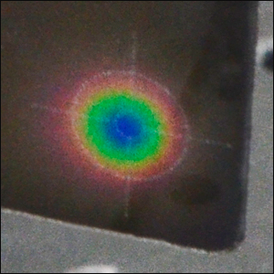
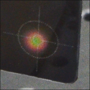
Click to Enlarge
Ø4.0 mm Spot at 2.0 mW/mm2
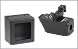
- Liquid Crystal Film Changes Color When Exposed to MIR Light
- Active Area: 2.13" x 1.81"
- Recovery Time: <10 Seconds
- Cards for Two Ambient Temperature Ranges Available:
- VRC6S: 20 to 24 °C
- VRC6H: 25 to 30 °C
- Overall Dimensions (W x H): 2.13" x 3.37"
The VRC6S and VRC6H MIR Liquid Crystal Detector Cards are designed to react to wavelengths from 1.5 µm to at least 13.2 µm. The detector area is a thin layer of thermochromic liquid crystals (TLC), which are temperature-sensitive organic chemicals with twisted helical molecular structures, protected by a mylar film. MIR light changes the temperature of the detector area, resulting in a color change. The detection region extends all the way to the edge of the card in order to facilitate the use of the card during alignment procedures, and each card features two engraved reticles for use in laser beam collimation. These cards feature enhanced sensitivity over competitor's offerings due to the TLC material used as well as the lack of backing on the detector area. The sensitivity achieved depends on the difference in temperature between the room and the LC material's activation temperature.
The VRC6S laser card is recommended for use with an ambient temperature of 20 to 24 °C and begins to show color changes when the TLC material reaches approximately 23 °C. The peak sensitivity and responsivity occur at an ambient temperature of 22 °C. The detector area is black below approximately 23 °C and turns blue/violet around 28 °C.
For room temperatures resting above the range of the VRC6S, the VRC6H is ideal. It is recommended for use with an ambient temperature of 25 to 30 °C and begins to show color changes when the TLC material reaches approximately 28 °C. The peak sensitivity and responsivity occur at an ambient temperature of 28 °C. The detector area is black below approximately 29 °C and turns blue/violet around 33 °C.
To restore a card after beam exposure, rest is on a flat on a table top (i.e. an optical table with stainless steel surface) for a few minutes. The cards may take longer to recover after exposure to higher laser energy, and sometimes the color change may look permanent at room temperature. If this occurs, place the cards in a refrigerator at 0 to 4 °C for a few minutes to accelerate the recovery.
Please Note: The spot size on these cards will vary depending on the beam power, as shown in the photos to the right.