 Products Home / Polarization Optics / Polarizers / Crystal Polarizers / Glan-Laser Calcite Polarizers
Glan-Laser Calcite Polarizers

- Designed for High-Power Laser Applications
- Extinction Ratio of 100 000:1
- Four AR-Coated Polarizer Options
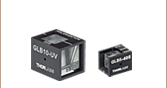
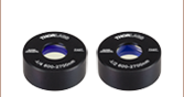
GL10P-B
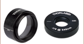
Unmounted Glan-Laser
Calcite Polarizer
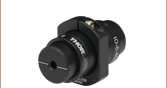
GL15-A
Mounted Glan-Laser
Calcite Polarizers
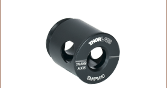
GL5-A
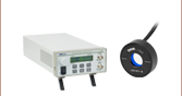
Application Idea
GL10-A Polarizer and SM1PM10
Mount on a PRM1 Rotation Mount
GL10-A


Please Wait
 Zemax Files Zemax Files |
|---|
| Click on the red Document icon next to the item numbers below to access the Zemax file download. Our entire Zemax Catalog is also available. |
Only the output ray (extraordinary ray) is highly polarized. A significant amount of reflected light escapes the polarizers through the side port, including all of the ordinary ray and some of the extraordinary ray. As such, the escape ray is not fully polarized.
Features
- Extinction Ratio for Output Beam: 100 000:1 (See Diagram in Lower Right for Details)
- Designed for High-Energy Lasers (see the Specs Tab for Damage Thresholds)
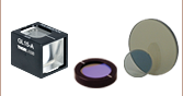
- Available Uncoated or with One of Four Broadband AR Coatings
- Uncoated: 350 nm - 2.3 µm Wavelength Range
- 350 - 700 nm Broadband AR Coating
- 650 - 1050 nm Broadband AR Coating
- 1050 - 1700 nm Broadband AR Coating
- 1064 nm V Coating
- Mounted with Ø5 mm, Ø10 mm, or Ø15 mm Clear Aperture or Unmounted
with Ø10 mm Clear Aperture - 20-10 Scratch-Dig Surface Quality on Input and Exit Faces (80-50 on Side Ports)
- Fabricated from Highest Grade, Laser-Quality Natural Calcite (Low Scatter)
- Glan-Taylor Design (Air-Spaced Birefringent Crystal Prisms)
- Select Polarizers Available Unmounted from Stock
The Glan-Laser Calcite Polarizer is a Glan-Taylor Calcite Polarizer that is specifically designed to deal with high-energy laser light. These polarizers are manufactured from select portions of the calcite crystal that must pass a laser scattering sensitivity test. Like our Glan-Taylor polarizers, these polarizers are ideal for applications requiring extremely high polarization purity (100,000:1) and high damage thresholds. A significant amount of reflected light escapes the polarizers through the side port, including all of the ordinary ray and some of the extraordinary ray. As such, the escape beam is not fully polarized, and only the transmitted extraordinary ray should be used for applications that require a high-quality, polarized beam.
The input and output faces of these polarizers are polished to a laser quality 20-10 scratch-dig surface finish to minimize scattering of the transmitted extraordinary polarization component of the incident laser beam or light field. The ordinary polarization component is reflected and exits the polarizer at a 68° angle (wavelength dependent) through one of the two uncoated side ports, which are provided to allow bidirectional use of the polarizer. The escape ray is not fully polarized and the side escape ports have a lower surface quality of 80-50 scratch-dig.
Uncoated calcite has a broad wavelength range (350 nm - 2.3 μm) and these polarizers are available with AR coatings over four wavelength ranges: 350 - 700 nm, 650 - 1050 nm, 1050 - 1700 nm, or 1064 nm. Only the input and output faces of the polarizer are AR coated; the exit and gap faces of the prisms are not coated. This design allows these polarizers to have high extinction ratios at the expense of lower overall transmission.
Our pre-mounted polarizers can be mounted inside our Polarizing Prism Mounts for compatibility with our SM05 (0.535"-40) or SM1 (1.035"-40) threads. The SM05PM5 provides SM05 compatibility for pre-mounted polarizers with Ø5 mm clear apertures, while the SM1PM10 and SM1PM15 provide SM1 compatibility for polarizers with Ø10 mm or Ø15 mm clear apertures, respectively.
| Item # Prefix | GL5 | GL10 | GL10P | GL15 |
|---|---|---|---|---|
| Extinction Ratioa | 100 000:1 | |||
| Substrate | Laser Quality Natural Calciteb (Low Scatter) | |||
| Transmitted Wavefront Error | ≤λ/4 Over Clear Aperture at 633 nm | |||
| Transmitted Beam Deviation | <3 arcmin | |||
| Surface Quality (Input and Output Faces) |
20-10 Scratch-Dig | |||
| Surface Quality (Exit Ports) | 80-50 Scratch-Dig | |||
| Clear Aperturec | Ø5.0 mm | Ø10.0 mm | Ø10.0 mm | Ø15.0 mm |
| Prism Dimensions (W x L)d | 6.5 mm x 7.5 mm | 12.2 mm x 13.7 mm | 12.2 mm x 16.5 mm | 17.2 mm x 21.6 mm |
| Coating Specifications | ||
|---|---|---|
| Coating Designatione | Reflectancef (Avg.) |
Damage Thresholdc |
| Uncoated (350 nm - 2.3 µm) | N/A | 20 J/cm2 (1064 nm, 10 ns, 10 Hz, Ø0.433 mm) |
| -A (350 - 700 nm) | <1% | 10 J/cm2 (532 nm, 10 ns, 10 Hz, Ø0.750 mm) |
| -B (650 - 1050 nm) | <1% | 10 J/cm2 (810 nm, 10 ns, 10 Hz, Ø0.155 mm) |
| -C (1050 - 1700 nm) | <1% | 10 J/cm2 (1542 nm, 10 ns, 10 Hz, Ø0.177 mm) |
| -C26 (1064 nm V Coating) | <0.25% | 15 J/cm2 (1064 nm, 10 ns, 10 Hz, Ø0.433 mm) |
Field of View Angle Orientation
A significant amount of reflected light escapes the polarizers through the side port, including all of the ordinary ray and some of the extraordinary ray. As such, the escape ray is not fully polarized. The output ray has a very pure polarization with an extinction ratio of 100 000:1.

Click to Enlarge
Raw Data
Note: Since calcite is a soft material, care must be taken when cleaning. The coated faces of the polarizer can be gently cleaned with solvent and air. The escape faces (uncoated and perpendicular to the input / exit faces) are extremely delicate and can be damaged very easily. Do not touch these faces if possible. Cleaning should be light and at a glancing angle. If these surfaces must be wiped, use only solvent-moistened cotton or untreated facial tissues.
Click to Enlarge
Click Here for Raw Data
The transmission graph above shows the typical transmission of calcite polarizers, including any internal losses. The transmission is valid for linearly polarized light aligned with the mark on the housing of the polarizer. Calcite is a natural material, and thus transmission can vary significantly, particularly in the UV and IR. Consequently, the performance data shown above may vary from lot to lot and is not guaranteed.
Click to Enlarge
Click Here for Raw Data
The AR coating graph above shows the typical surface reflections associated with each of the AR coatings offered on our Glan-Laser Calcite Polarizers. Please note that this data represents the performance of the surface coating and does not include any internal losses.
Mounted Glan-Laser Dimensions
| Item # | GL5 | GL10 | GL15 |
|---|---|---|---|
| W | 6.5 mm | 12.2 mm | 17.2 mm |
| La | 7.5 mm | 13.7 mm | 21.6 mm |
| A | 9.5 mm | 15.9 mm | 22.2 mm |
| B | 12.7 mm | 19.1 mm | 25.4 mm |
Unmounted Glan-Laser Dimensions
| Item # | GL10P |
|---|---|
| W | 12.2 mm |
| La | 16.5 mm |
| A | 12.2 mm |
General
Our calcite polarizers are all based on high-grade, birefringent calcite crystals. Due to the birefringent nature of calcite, waves polarized in the direction of the optical axis propagate with a different index of refraction than waves polarized orthogonally to the optical axis. In our Glan-Taylor polarizers, this birefringence causes the ordinary polarization component of an incident beam to undergo total internal reflection at an internal glass-to-air interface. The light transmitted through the polarizer then consists of only the remaining extraordinary polarization component. While these transmitted extraordinary rays are highly polarized, the reflected ordinary rays are only partially polarized.
Our Glan-Laser and Glan-Taylor polarizers are designed as polarizer elements that remove the reflected ordinary polarization component of a beam. These polarizers are built out of two prisms, as shown in the drawing to the right. They are only designed to work with well collimated light beams; converging and diverging input beams will not exhibit proper polarization and incidence angle at the internal interface. Since calcite is a soft crystal that is easily damaged, almost all of our calcite polarizers are offered in metal housings. With convenient threadings and adapters, these housings can easily be mounted into our opto-mechanical products.
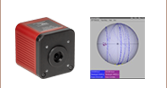
Field of View
Calcite polarizers feature a field of view (FOV) that varies with both wavelength and entrance orientation. The FOV of these prisms must be considered during alignment and collimation procedures.
As seen in the drawing and graph below and to the right, the side of the polarizer with the escape window has an FOV that decreases as the wavelength increases (FOV 1). The opposite side has an FOV that increases as the wavelength increases (FOV 2).
Transmission
Thorlabs uses only the highest quality natural calcite in our polarizing prisms. Typical transmission curves for these polarizers may be found on the Graphs tab. Because calcite is a naturally occuring material, variations in the crystal affect the transmission curve and the damage threshold rating. Variations in the calcite transmission curve are typically limited to wavelengths > 2 μm, making calcite an excellent material to use in the visible and NIR.
| Thorlabs' Calcite Polarizers | ||
|---|---|---|
| Glan-Laser Polarizers | Glan-Taylor Polarizers | Wollaston Polarizers |
| Glan-Thompson Polarizers Mounted or Unmounted |
Double Glan-Taylor Polarizer | Beam Displacers |
| Damage Threshold Specifications | |
|---|---|
| Coating Designation (Item # Suffix) |
Damage Threshold |
| (Uncoated) | 20 J/cm2 (1064 nm, 10 ns, 10 Hz, Ø0.433 mm) |
| -A | 10 J/cm2 (532 nm, 10 ns, 10 Hz, Ø0.750 mm) |
| -B | 10 J/cm2 (810 nm, 10 ns, 10 Hz, Ø0.155 mm) |
| -C | 10 J/cm2 (1542 nm, 10 ns, 10 Hz, Ø0.177 mm) |
| -C26 | 15 J/cm2 (1064 nm, 10 ns, 10 Hz, Ø0.433 mm) |
Damage Threshold Data for Thorlabs' Glan-Laser Calcite Polarizers
The specifications to the right are measured data for Thorlabs' Glan-laser calcite polarizer. Damage threshold specifications are constant for a given coating type, regardless of the size of the polarizer.
Care should be taken to ensure that the polarizer's clear aperture is large enough for your beam, and that the polarizer is well aligned. While each polarizer is air-spaced within the clear aperture, the prisms composing the polarizer are separated by an epoxied photo-etched spacer that is not designed to withstand high laser powers. Using these parts outside of the clear aperture can result in catastrophic damage and failure.
Laser Induced Damage Threshold Tutorial
The following is a general overview of how laser induced damage thresholds are measured and how the values may be utilized in determining the appropriateness of an optic for a given application. When choosing optics, it is important to understand the Laser Induced Damage Threshold (LIDT) of the optics being used. The LIDT for an optic greatly depends on the type of laser you are using. Continuous wave (CW) lasers typically cause damage from thermal effects (absorption either in the coating or in the substrate). Pulsed lasers, on the other hand, often strip electrons from the lattice structure of an optic before causing thermal damage. Note that the guideline presented here assumes room temperature operation and optics in new condition (i.e., within scratch-dig spec, surface free of contamination, etc.). Because dust or other particles on the surface of an optic can cause damage at lower thresholds, we recommend keeping surfaces clean and free of debris. For more information on cleaning optics, please see our Optics Cleaning tutorial.
Testing Method
Thorlabs' LIDT testing is done in compliance with ISO/DIS 11254 and ISO 21254 specifications.
First, a low-power/energy beam is directed to the optic under test. The optic is exposed in 10 locations to this laser beam for 30 seconds (CW) or for a number of pulses (pulse repetition frequency specified). After exposure, the optic is examined by a microscope (~100X magnification) for any visible damage. The number of locations that are damaged at a particular power/energy level is recorded. Next, the power/energy is either increased or decreased and the optic is exposed at 10 new locations. This process is repeated until damage is observed. The damage threshold is then assigned to be the highest power/energy that the optic can withstand without causing damage. A histogram such as that below represents the testing of one BB1-E02 mirror.

The photograph above is a protected aluminum-coated mirror after LIDT testing. In this particular test, it handled 0.43 J/cm2 (1064 nm, 10 ns pulse, 10 Hz, Ø1.000 mm) before damage.

| Example Test Data | |||
|---|---|---|---|
| Fluence | # of Tested Locations | Locations with Damage | Locations Without Damage |
| 1.50 J/cm2 | 10 | 0 | 10 |
| 1.75 J/cm2 | 10 | 0 | 10 |
| 2.00 J/cm2 | 10 | 0 | 10 |
| 2.25 J/cm2 | 10 | 1 | 9 |
| 3.00 J/cm2 | 10 | 1 | 9 |
| 5.00 J/cm2 | 10 | 9 | 1 |
According to the test, the damage threshold of the mirror was 2.00 J/cm2 (532 nm, 10 ns pulse, 10 Hz, Ø0.803 mm). Please keep in mind that these tests are performed on clean optics, as dirt and contamination can significantly lower the damage threshold of a component. While the test results are only representative of one coating run, Thorlabs specifies damage threshold values that account for coating variances.
Continuous Wave and Long-Pulse Lasers
When an optic is damaged by a continuous wave (CW) laser, it is usually due to the melting of the surface as a result of absorbing the laser's energy or damage to the optical coating (antireflection) [1]. Pulsed lasers with pulse lengths longer than 1 µs can be treated as CW lasers for LIDT discussions.
When pulse lengths are between 1 ns and 1 µs, laser-induced damage can occur either because of absorption or a dielectric breakdown (therefore, a user must check both CW and pulsed LIDT). Absorption is either due to an intrinsic property of the optic or due to surface irregularities; thus LIDT values are only valid for optics meeting or exceeding the surface quality specifications given by a manufacturer. While many optics can handle high power CW lasers, cemented (e.g., achromatic doublets) or highly absorptive (e.g., ND filters) optics tend to have lower CW damage thresholds. These lower thresholds are due to absorption or scattering in the cement or metal coating.

LIDT in linear power density vs. pulse length and spot size. For long pulses to CW, linear power density becomes a constant with spot size. This graph was obtained from [1].

Pulsed lasers with high pulse repetition frequencies (PRF) may behave similarly to CW beams. Unfortunately, this is highly dependent on factors such as absorption and thermal diffusivity, so there is no reliable method for determining when a high PRF laser will damage an optic due to thermal effects. For beams with a high PRF both the average and peak powers must be compared to the equivalent CW power. Additionally, for highly transparent materials, there is little to no drop in the LIDT with increasing PRF.
In order to use the specified CW damage threshold of an optic, it is necessary to know the following:
- Wavelength of your laser
- Beam diameter of your beam (1/e2)
- Approximate intensity profile of your beam (e.g., Gaussian)
- Linear power density of your beam (total power divided by 1/e2 beam diameter)
Thorlabs expresses LIDT for CW lasers as a linear power density measured in W/cm. In this regime, the LIDT given as a linear power density can be applied to any beam diameter; one does not need to compute an adjusted LIDT to adjust for changes in spot size, as demonstrated by the graph to the right. Average linear power density can be calculated using the equation below.

The calculation above assumes a uniform beam intensity profile. You must now consider hotspots in the beam or other non-uniform intensity profiles and roughly calculate a maximum power density. For reference, a Gaussian beam typically has a maximum power density that is twice that of the uniform beam (see lower right).
Now compare the maximum power density to that which is specified as the LIDT for the optic. If the optic was tested at a wavelength other than your operating wavelength, the damage threshold must be scaled appropriately. A good rule of thumb is that the damage threshold has a linear relationship with wavelength such that as you move to shorter wavelengths, the damage threshold decreases (i.e., a LIDT of 10 W/cm at 1310 nm scales to 5 W/cm at 655 nm):

While this rule of thumb provides a general trend, it is not a quantitative analysis of LIDT vs wavelength. In CW applications, for instance, damage scales more strongly with absorption in the coating and substrate, which does not necessarily scale well with wavelength. While the above procedure provides a good rule of thumb for LIDT values, please contact Tech Support if your wavelength is different from the specified LIDT wavelength. If your power density is less than the adjusted LIDT of the optic, then the optic should work for your application.
Please note that we have a buffer built in between the specified damage thresholds online and the tests which we have done, which accommodates variation between batches. Upon request, we can provide individual test information and a testing certificate. The damage analysis will be carried out on a similar optic (customer's optic will not be damaged). Testing may result in additional costs or lead times. Contact Tech Support for more information.
Pulsed Lasers
As previously stated, pulsed lasers typically induce a different type of damage to the optic than CW lasers. Pulsed lasers often do not heat the optic enough to damage it; instead, pulsed lasers produce strong electric fields capable of inducing dielectric breakdown in the material. Unfortunately, it can be very difficult to compare the LIDT specification of an optic to your laser. There are multiple regimes in which a pulsed laser can damage an optic and this is based on the laser's pulse length. The highlighted columns in the table below outline the relevant pulse lengths for our specified LIDT values.
Pulses shorter than 10-9 s cannot be compared to our specified LIDT values with much reliability. In this ultra-short-pulse regime various mechanics, such as multiphoton-avalanche ionization, take over as the predominate damage mechanism [2]. In contrast, pulses between 10-7 s and 10-4 s may cause damage to an optic either because of dielectric breakdown or thermal effects. This means that both CW and pulsed damage thresholds must be compared to the laser beam to determine whether the optic is suitable for your application.
| Pulse Duration | t < 10-9 s | 10-9 < t < 10-7 s | 10-7 < t < 10-4 s | t > 10-4 s |
|---|---|---|---|---|
| Damage Mechanism | Avalanche Ionization | Dielectric Breakdown | Dielectric Breakdown or Thermal | Thermal |
| Relevant Damage Specification | No Comparison (See Above) | Pulsed | Pulsed and CW | CW |
When comparing an LIDT specified for a pulsed laser to your laser, it is essential to know the following:

LIDT in energy density vs. pulse length and spot size. For short pulses, energy density becomes a constant with spot size. This graph was obtained from [1].
- Wavelength of your laser
- Energy density of your beam (total energy divided by 1/e2 area)
- Pulse length of your laser
- Pulse repetition frequency (prf) of your laser
- Beam diameter of your laser (1/e2 )
- Approximate intensity profile of your beam (e.g., Gaussian)
The energy density of your beam should be calculated in terms of J/cm2. The graph to the right shows why expressing the LIDT as an energy density provides the best metric for short pulse sources. In this regime, the LIDT given as an energy density can be applied to any beam diameter; one does not need to compute an adjusted LIDT to adjust for changes in spot size. This calculation assumes a uniform beam intensity profile. You must now adjust this energy density to account for hotspots or other nonuniform intensity profiles and roughly calculate a maximum energy density. For reference a Gaussian beam typically has a maximum energy density that is twice that of the 1/e2 beam.
Now compare the maximum energy density to that which is specified as the LIDT for the optic. If the optic was tested at a wavelength other than your operating wavelength, the damage threshold must be scaled appropriately [3]. A good rule of thumb is that the damage threshold has an inverse square root relationship with wavelength such that as you move to shorter wavelengths, the damage threshold decreases (i.e., a LIDT of 1 J/cm2 at 1064 nm scales to 0.7 J/cm2 at 532 nm):

You now have a wavelength-adjusted energy density, which you will use in the following step.
Beam diameter is also important to know when comparing damage thresholds. While the LIDT, when expressed in units of J/cm², scales independently of spot size; large beam sizes are more likely to illuminate a larger number of defects which can lead to greater variances in the LIDT [4]. For data presented here, a <1 mm beam size was used to measure the LIDT. For beams sizes greater than 5 mm, the LIDT (J/cm2) will not scale independently of beam diameter due to the larger size beam exposing more defects.
The pulse length must now be compensated for. The longer the pulse duration, the more energy the optic can handle. For pulse widths between 1 - 100 ns, an approximation is as follows:

Use this formula to calculate the Adjusted LIDT for an optic based on your pulse length. If your maximum energy density is less than this adjusted LIDT maximum energy density, then the optic should be suitable for your application. Keep in mind that this calculation is only used for pulses between 10-9 s and 10-7 s. For pulses between 10-7 s and 10-4 s, the CW LIDT must also be checked before deeming the optic appropriate for your application.
Please note that we have a buffer built in between the specified damage thresholds online and the tests which we have done, which accommodates variation between batches. Upon request, we can provide individual test information and a testing certificate. Contact Tech Support for more information.
[1] R. M. Wood, Optics and Laser Tech. 29, 517 (1998).
[2] Roger M. Wood, Laser-Induced Damage of Optical Materials (Institute of Physics Publishing, Philadelphia, PA, 2003).
[3] C. W. Carr et al., Phys. Rev. Lett. 91, 127402 (2003).
[4] N. Bloembergen, Appl. Opt. 12, 661 (1973).
| Posted Comments: | |
Antonio Polimeni
(posted 2023-05-27 16:22:05.53) We purchased two GL10 and we have not opened the polarizer box, yet.
Indeed, we noted this warning:
"Calcite is a temperature-sensitive crystal and will crack if it is exposed to thermal shock. Allow the shipping packaging to reach complete thermal equilibrium before opening (6 - 8 hours)."
Honestly, we do not understand what this really means. The polarizer was delivered in a standard box from the factory and we guess that no special care was used during transportation as far as the temperature stability was concerned. Therefore, what "reaching thermal equilibrium" means is not easily understandable.
Furthermore, we will use the polariser within a high-power laser application, where we are sure that a large temperature gradient will develop locally when the laser pulses will pass through the polarizer.
Please, let us know so that, in case, we can change this item (the boxes containing the polarisers have been not opened). cdolbashian
(posted 2023-06-01 04:51:18.0) Thank you for reaching out to us with this inquiry. This is a good point and in most cases there is no harm in removing them from the packaging and using the products. However, in a situation where the component is very cold and is brought into a warm laboratory environment, the total effect of thermal expansion on the entire component can lead to cracking, which we have observed in the past. The packaging provides sufficient insulation to slow this process down such that the crystals will not crack. This is why we recommend the thermal equilibration before use. stephen chinn
(posted 2022-10-31 06:10:01.43) Can this product be supplied with 1.91um V-coat AR, or 1700nm coating extended to 2000nm?
If provided with no coating, what temperature constraints apply for external coating suppliers? cdolbashian
(posted 2022-11-08 02:08:03.0) Thank you for reaching out to us Stephen. This seems feasible as a custom. I have reached out to you directly to discuss it. For future custom requests, please email techsales@thorlabs.com. kedves
(posted 2016-12-07 14:04:57.62) Dear Thorlabs,
How sensitive is the extinction ratio of GL15 to the alignment of the crystal? We are speculating whether we should choose one with or without AR-coating. In any case, the perpendicular reflection must be avoided (without AR-coating by a larger margin). Is my understanding correct that the FOV given (~6 degrees) means that within this angle the extinction ratio of 100000:1 can be reached? That would be more that enough for avoiding back-reflections, and a crystal without coating would mean higher damage threshold and more universal applicability.
Best regards tfrisch
(posted 2016-12-22 11:24:44.0) Hello, thank you for contacting Thorlabs. The FOV is the range for which the total internal reflection condition would be met for the rejected polarization state. I will reach out to you directly with more details. umo
(posted 2015-12-07 12:32:31.98) Do you have transmission and reflection data up to 950nm for your A-coating (eg on GL5-A)? besembeson
(posted 2015-12-07 11:00:56.0) Response from Bweh at Thorlabs USA: I will share the extended reflection data with you via email. We would recommend the GL5-B for such a wavelength though. mcg6
(posted 2015-06-10 14:32:36.903) Can you provide information on the damage threshold of GL10-A when exposed to 355nm light? We are looking at 5-10ns pulses. besembeson
(posted 2015-09-03 03:43:55.0) Response from Bweh at Thorlabs USA: Unfortunately we don't have any pulsed laser induced damage threshold data in the UV for this polarizer, but it would be much worse than at 1064nm. I would recommend you consider instead, the GLB10 Glan-Laser ?-BBO Polarizer that is specifically designed to deal with high-energy, short-wavelength laser light: http://www.thorlabs.us/thorproduct.cfm?partnumber=GLB10-UV curtis.volin
(posted 2013-08-20 10:33:18.683) Can you post transmission data in addition to the plot? I am interested in the 350-400nm range, but the resolution of the plot makes it difficult to get a quantitative estimate at short wavelengths. sharrell
(posted 2013-08-20 13:32:00.0) Thank you for your feedback. We’ve attached the transmission data for the Glan-Laser Polarizers as a link under the graph, and sent you the file directly via email. tcohen
(posted 2012-07-19 11:02:00.0) Response from Tim at Thorlabs: Thank you for contacting us! This polarizer will induce dispersion that will cause temporal broadening of your source. The level of importance will of course depend on your application. We don't have your email, but would like to go over this within the context of your application. To continue this conversation, please contact us at techsupport@thorlabs.com. user
(posted 2012-07-17 22:00:30.0) I'm interested in using a few glan laser polarizers with a 100 fs pulsed laser. I know this product has not been tested for ultrashort applications, but is there an obvious reason it wouldn't work? bdada
(posted 2012-02-24 18:58:00.0) Response from Buki at Thorlabs to jmmelkon:
Thank you so much for your feedback and for sharing your results with us. Please contact TechSupport@thorlabs.com if you want to discuss your application further. jmmelkon
(posted 2012-02-24 15:18:19.0) I may have found the reason for the excellent extinction ratio. Along with the output ray there is a very weak off-axis parasitic beam. I don't know how it is polarized or whether it could come from a residual reflexion from the output window's coating. Anyway, by spatially filtering out this beam, you can reach a 2.10^7 ratio.
Note that the PRM1 mount proved to be very useful in doing these measurements. user
(posted 2011-12-09 09:23:32.0) A response from Tyler at Thorlabs: Hello Jean Michel, Our specifications for the extinction ratio of calcium polarizers is conservative but I would like to have you discuss your test with an applications engineer. I will forward your questions to them and they will contact you directly. jean-michel.melkonian
(posted 2011-12-07 17:57:00.0) I measure an extinction ratio (Pout/Pin for e ray) of 2.10^7, i.e. 2 order of magnitude better than the specified value of 100'000:1.
Conditions: 1064 nm, 200 ns, 10 kHz, 12 W, 2 mm beam diameter, 1 mrad half-divergence. Input polarization is as linear as it could be after filtering by 2 similar polarizers.
Is the specified value (very) conservative, refer to another definition, or my measurement more likely wrong?
Thanks. jjurado
(posted 2011-05-17 09:51:00.0) Response from Javier at Thorlabs to huang.changhan: Thank you very much for contacting us. The calcite polarizer itself can be placed in vacuum; however, the black anodized mount it comes in will most likely outgass at levels lower than 10^3 Torr. Alternatively, we can offer an unmounted version of the GL10-A to you. I will contact you directly for further assistance. huang.changhan
(posted 2011-05-09 16:10:03.0) Can GL10-A be placed in the vacuum? jjurado
(posted 2011-03-11 16:44:00.0) Response from Javier at Thorlabs to Marc: Thank you for contacting us. Although we do not have a specification for the maximum divergence allowed when using this polarizer, 60 urad should be fine for almost every purpose, so we do not expect this to be the reason for the double beam. There are a variety of possible causes that we could consider:
(1) Measuring divergence across a focus, so the beam appears more collimated than what it actually is (say the measurement was made on each side of a waist, when the beam is actually divergent).
(2) Using polarizer at a wavelength where it is highly reflective.
(3) Misalignment of the polarizer.
(4) Misalignment of the other optics in the system.
(5) Placing too much stress on one of the optics in the system (polarizer, lenses, or others), causing stress birefringence.
(6) Defective polarizer.
I will contact you directly for further troubleshooting. marc.le-parquier
(posted 2011-03-09 10:52:48.0) Hello,
In specs section its noted that a divergent beam produce multiple output. Which is the maximum divergence allowed. My beam is around 60µrad and I try to image it on a camera with 100mm focal length lenses and another one around 1m FL. The two lenses produce a double image of beam and is not due to the lenses because with no lenses we already can seen the beginning of double Gaussian on the ccd (the two are mixed in one ellipsoid).
Is it possible with only 60µrad divergence? Or perhaps is due to a misalignment of GL15-B ?
Thank you
Best regards
Marc tor
(posted 2010-11-11 12:01:41.0) Response from Tor at Thorlabs to luis.dussan: Please note that this is a conservative estimate. We are currently working on testing damage thresholds of many of our optics. I will contact you shortly to determine which polarizers are most suitable for you. luis.dussan
(posted 2010-11-11 09:04:13.0) 10J/cm^2...Why so low? tor
(posted 2010-11-09 16:16:27.0) Response from Tor at Thorlabs to luis.dussan:
Thank you for your inquiry. Our Optics Department advises that 10J/cm^2 can be expected for your input parameters. Please do not hesitate to contact us if you require further information. luis.dussan
(posted 2010-11-09 11:29:47.0) For the -C coating what is the Fluence DT at 1550nm and 10ns 20Hz.
Thanks Thorlabs
(posted 2010-07-14 11:33:10.0) Response from Javier at Thorlabs to james.hanssen: thank you for your feedback. I will send you theoretical data for the transmission through our GL10 calcite polarizer. We will generate test data shortly and post our results. |
Polarizer Selection Guide
Thorlabs offers a diverse range of polarizers, including wire grid, film, calcite, alpha-BBO, rutile, and beamsplitting polarizers. Collectively, our line of wire grid polarizers offers coverage from the visible range to the beginning of the Far-IR range. Our nanoparticle linear film polarizers provide extinction ratios as high as 100 000:1. Alternatively, our other film polarizers offer an affordable solution for polarizing light from the visible to the Near-IR. Next, our beamsplitting polarizers allow for use of the reflected beam, as well as the more completely polarized transmitted beam. Finally, our alpha-BBO (UV), calcite (visible to Near-IR), rutile (Near-IR to Mid-IR), and yttrium orthovanadate (YVO4) (Near-IR to Mid-IR) polarizers each offer an exceptional extinction ratio of 100 000:1 within their respective wavelength ranges.
To explore the available types, wavelength ranges, extinction ratios, transmission, and available sizes for each polarizer category, click More [+] in the appropriate row below.
| Wire Grid Polarizers |
|---|
| Film Polarizers |
|---|


| Beamsplitting Polarizers |
|---|


| alpha-BBO Polarizers |
|---|
| Calcite Polarizers |
|---|
| Quartz Polarizers |
|---|
| Magnesium Fluoride Polarizers |
|---|
| Yttrium Orthovanadate (YVO4) Polarizers |
|---|
| Rutile Polarizers |
|---|
The transmittance of calcite near 350 nm is typically around 75% (see Graphs tab). For applications in the UV, we suggest using a-BBO polarizers as they offer superior UV transmittance. It is not recommended to use these polarizers for input beams with wavelengths greater than 2.3 µm, as calcite has different absorption coefficients for the ordinary and extrarodinary rays that diverge past this point.
The AR coating used for these polarizers is designed for 350 - 700 nm and has an average reflectance of <1% over the AR coating range, however, calcite's transmittance is diminished in the UV (see Graphs tab above for transmission and reflectance curves). Thorlabs recommends using a-BBO polarizers for UV applications.