 Products Home / Technical Resources / Optical Elements Technical Publications / Optics Handling and Care Tutorial
Optics Handling and Care Tutorial


Please Wait

Handling and Cleaning Procedures for Optical Components
The delicate nature of optical components requires that special procedures be followed in order to maximize their performance and lifetime. Through everyday use, optics can come in contact with contaminants such as dust, water, and skin oils. These contaminants increase scatter off the optical surface and absorb incident radiation, which can create hot spots on the optical surface, resulting in permanent damage. Optical components with coatings are particularly susceptible to this sort of damage.
The content of this guide covers common handling and cleaning procedures that are applicable to many optical components. Due to variation in materials, size, delicacy, etc. of optical components, it is important that the correct handling and cleaning methods are used. What is okay for one type of optical component will destroy another type of optical component. Because of this, we recommend that the guide be read in its entirety before cleaning an optic. If the type or category of optic is not specifically mentioned in the guide, please contact the optical component manufacturer for handling and cleaning instructions.
Handling
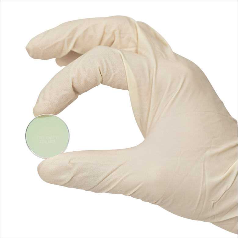
By practicing proper handling techniques, you will decrease the necessity to clean your optics and thus maximize their lifetime. Always unpack or open optics in a clean, temperature-controlled environment. Never handle optics with bare hands, as skin oils can permanently damage the optical surface quality. Instead, wear gloves; alternatively, for smaller optical components, it may be helpful to use optical or vacuum tweezers. Independent of the method used to hold the optic, if at all possible, only hold the optic along non-optical surfaces, such as the ground edges of the optic.
Important: The optical surface of holographic gratings, ruled gratings, first surface unprotected metallic mirrors, and pellicle beamsplitters (this is not an exhaustive list) should never be touched by hands or optical handling instruments. They are extremely sensitive, and any physical contact will cause damage.
Caution: Most crystals (e.g., calcite polarizers, beam displacers, lithium niobate wafers, and EO modulators) are temperature sensitive and can crack if exposed to thermal shock. Therefore, it is important to always allow the package and contents to come to thermal equilibrium prior to opening. These crystals are also much softer than conventional optics, and thus, need to be handled more carefully when cleaning.
Storage
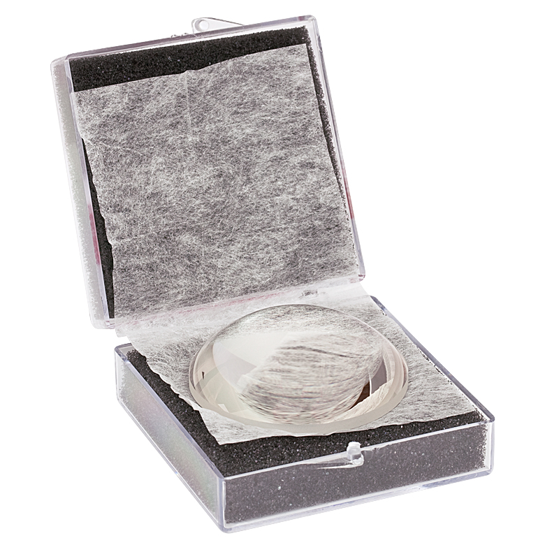
Never place optics on hard surfaces because any contaminant on the optic or the surface will be ground in. Instead, most optics should be wrapped in lens tissue and then stored inside an optic storage box designed for the optic. Typically, the box should be kept in a low humidity, low contaminant, and temperature-controlled environment. Optics are easily scratched or contaminated, and some optical coatings are hygroscopic, so proper storage is important for preserving the optical component.
Inspection
In general, optics should be inspected prior to use and before and after cleaning. It is often necessary to use a magnification device when inspecting an optical component due to the small size of most contaminants and surface defects. Even with a magnification device, it is sometimes useful to shine a bright light onto the optical surface in order to increase the intensity of the specular reflections from surface contaminants and defects.
When inspecting a reflectively coated surface, the optic should be held nearly parallel to your line of sight. By looking across the surface rather than directly at it, you will see contamination and not reflections. Polished surfaces such as lenses should be held perpendicular to your line of sight so that you can look through the optic.
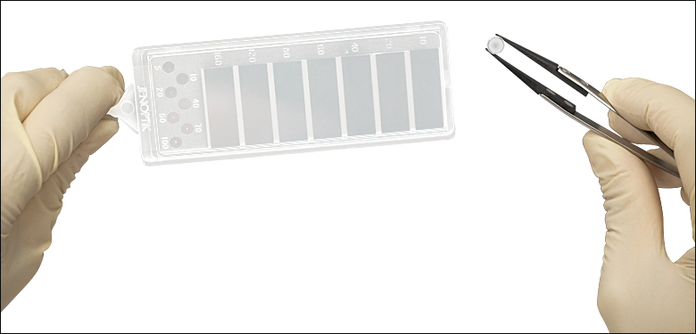
If a surface defect is located on a clean optical surface, a scratch-dig paddle can be used to categorize the size of the defect by comparing the size of the calibrated defects on the scratch-dig paddle to the size of the defects on the surface of the optic. If the size of the defect on the surface exceeds the manufacturer’s scratch-dig specification, it may be necessary to replace the optic in order to achieve the desired performance.
Cleaning Procedures
Always read the manufacturer’s recommended cleaning and handling procedures if available. Since cleaning an optic almost invariably involves handling it, please make sure to follow the proper handling procedures at all times when using the cleaning guideline discussed below. Optics can be permanently damaged if cleaned or handled incorrectly.
Before cleaning an optic, take time to inspect the optic in order to determine the type and severity of the contaminants. This inspection step should not be skipped because the process of cleaning the optic often involves solvents and physical contact with the optical surface, which can result in damage to the optical surface if repeated too frequently.
For optics with multiple contaminants, the order with which they are removed can be important so that the optical surface is not damaged by one contaminant while removing a separate contaminant. For instance, if an optic is contaminated with oil and dust, it is possible that wiping the oil off first will scratch the optical surface as the dust is drug along the surface by the wipe.
Blowing Off the Surface of an Optic
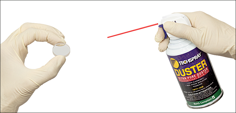
Dust and other loose contaminants usually should be blown off before any other cleaning technique is employed. A canister of inert dusting gas or a blower bulb is needed for this method. Do not use your mouth to blow on the surface because it is likely that droplets of saliva will be deposited on the optical surface.
If you are using inert dusting gas, hold the can upright before and throughout the procedure. Do not shake the can prior to or during use. Also, start the flow of gas with the nozzle pointed away from the optic. These steps help prevent the deposition of the inert gas propellant on the optical surface. If using canned gas, hold the can roughly 6” (15 cm) from the optic and use short blasts. Wave the nozzle of the inert gas can over the optic with the nozzle at a grazing angle to the optical surface. For large surfaces, trace a figure-eight pattern over the optical surface.
This cleaning method can be used on almost all types of optics. However, for some optics such as holographic gratings, ruled gratings, unprotected metallic mirrors, calcite polarizers, and pellicle beamsplitters, which can be damaged by physical contact, this is the only approved method for cleaning. Due to the non-contact and solvent-free nature of this cleaning method, it should be used as a first step in cleaning almost all optics.
Caution: The 2 μm thick Nitrocellulose membrane on pellicle beamsplitters is extremely fragile and easily broken by the force of air on the surface. If using canned air with these optics, ensure that the bottle is sufficiently far away so as not to break the membrane.
Caution: The polished escape face on calcite polarizers is very delicate and can be damaged by blowing air too directly at the surface.
Alternative Cleaning Methods
If blowing off the surface of the optic is not sufficient, the following are other acceptable cleaning methods and materials. When cleaning an optic, always use clean wipes and optical grade solvents to prevent damage from contaminants. Wipes should always be moist with an acceptable solvent and never used dry. Acceptable wipes (in order of softness) are pure cotton (such as Webril Wipes or Cotton Balls), lens tissue, and cotton-tipped applicators.
Typical solvents employed during cleaning are acetone, methanol, and isopropyl alcohol (isopropanol). Use all solvents with caution since most are poisonous, flammable, or both. Read product data sheets and MSDS sheets carefully before using any solvents.
Washing the Optic
If approved by the manufacturer, fingerprints and large dust particles can be removed by immersing the optic in a mild solution of distilled water and optical soap. The optic should not remain immersed any longer than necessary to remove the contaminants. Afterwards, rinse the optic in clean distilled water. Depending on the optic, the Drop and Drag or Lens Tissue (applicator) methods can be used to apply a quick-drying solvent like acetone or methanol to the optic to accelerate drying. Avoid pooling of any cleaning solutions as they dry because that tends to leave streaks on the optical surface.
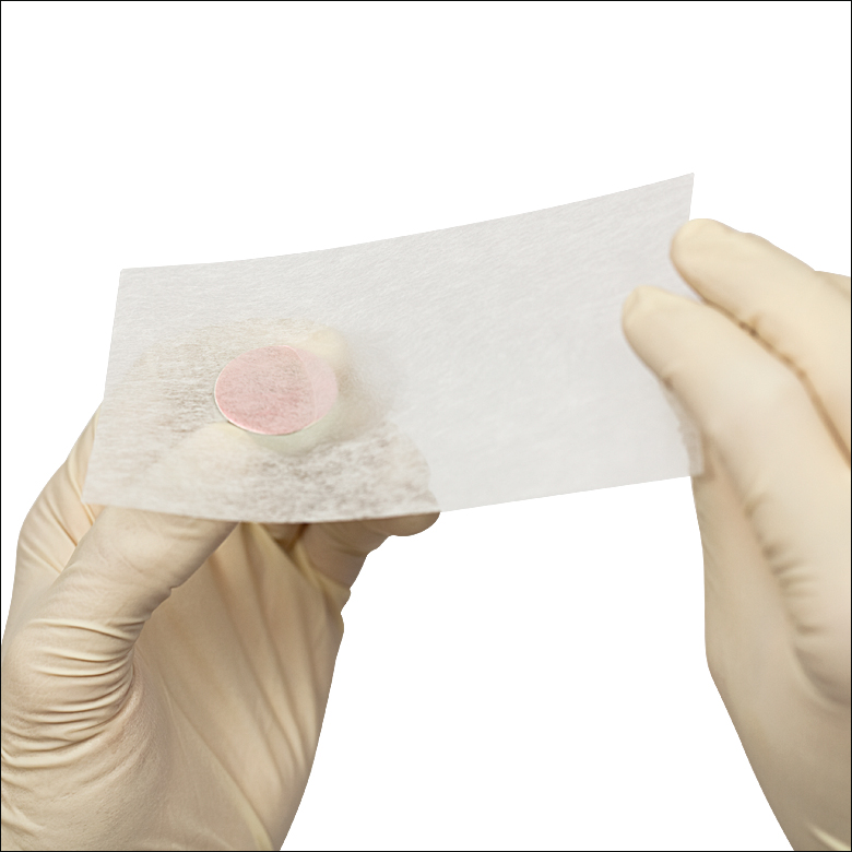
Drop and Drag Method
The Drop and Drag Method can be used for cleaning flat optical surfaces that are elevated above any surrounding surfaces. First, inspect the optic to determine the location of the contaminants. This allows you to plan your drag so that the contaminant is lifted from the surface of the optic as soon as possible instead of being dragged across the surface of the optic. After inspection, place or hold the optic so that a weak lateral force on the surface will not cause the optic to move. Take a fresh, clean sheet of lens tissue and hold it above (not in contact) the optic so that as you pull the lens tissue it will be drawn across the optical surface. Next place one or two drops of an approved quick drying solvent on the lens tissue being held above the optic. The weight of the solvent will cause the lens tissue to come into contact with the optical surface. Slowly but steadily drag the damp lens tissue across the optic being careful not to lift the lens tissue off of the surface. Continue dragging the lens tissue until it is off of the optical surface.
The correct amount of solvent will keep the lens tissue damp for the entire drag but not leave any visible trace of solvent on the optical surface after the drag is finished. Inspect the optic and repeat if necessary, but only use each sheet of lens tissue once. This cleaning method is preferred by many since the lens tissue is only in light contact with the optical surface. This method can be used successfully to remove small adhered particles and oils from an optical surface. Heavy concentrations of contaminants often require repeated treatments.
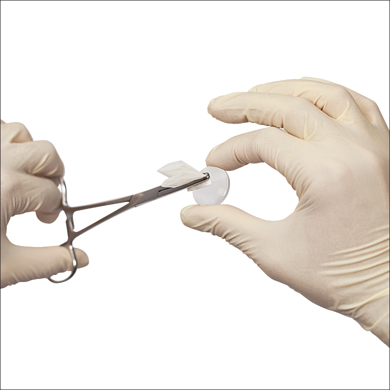
Lens Tissue with Forceps or Applicator Method
This method is often used with mounted or curved surface optics that require cleaning with a solvent. Inspect the optic to locate the sources of contamination. Plan a wiping path that will not result in dragging any large contaminants over more of the optical surface than is necessary. If lens tissue is used, it is important to fold the tissue in such a way that the portion of tissue that comes into contact with the optic is not touched. Clamp the folded lens tissue with forceps in such a way that a smooth wipe over the optical surface can be executed. Next, apply a couple of drops of solvent to the lens tissue. The tissue should be damp, but not dripping. If too much solvent was added, safely shake the excess solvent from the lens tissue. The lens tissue should now be wiped over the optical surface in a smooth motion.
During the wipe, continuously, but slowly, rotate the lens tissue. This will continuously change the portion in contact with the optical surface, which will rotate upward and away from the surface any accumulated contaminants. After the wipe, inspect the optic for any remaining contaminants or streaks and repeat the cleaning procedure if necessary with a new lens tissue. Streaks tend to form if too much solvent was on the lens tissue or on the optical surface where the edge of the tissue was wiped. If streaks are forming at the edge of the lens tissue, choose a larger applicator or plan a continuous wiping path that eliminates the wiped interface on the optical surface. If a spiral or snaking wipe path is used, it might be necessary to use a slower drying solvent so that the optical surface doesn’t dry until the wipe is complete.
Cleaning with Webril Wipes
Webril Wipes are soft, pure-cotton wipers that are highly recommended for cleaning most optics. They hold solvent well, do not dry out as fast as lens tissue or cotton-tipped applicators, and do not fall apart quickly like some other wipes. The outside edges of these wipes may leave some lint, so always use a folded edge when cleaning.
For smaller optics, roll the Webril wipe into a cone with the folded edge at the point, moisten the tip with a solvent and use the point as the wiping area. For larger optics, first cut the wipe into three pieces that are approximately 2.6” x 4”. Fold the wipe length wise so that it now measures 1.3” x 4”, and then make a fold approximately 1” from the end. Moisten the final folded edge with solvent and use that edge to wipe/clean the optical surface. Using a pump bottle to dispense the solvent will make it easier to hold the optic in one hand while moistening the wipe with the other.
During cleaning, wear gloves or finger cots. Pick up the optic in one hand and then wipe the Webril wipe lightly, continuously, and slowly across the entire surface of the optic so as to avoid streaking. You may need to adjust the amount of solvent, pressure applied to the wipe, and/or speed of the wipe to avoid streaks. Wiping times will also vary with solvent. For instance, if using acetone, you would need to wipe slightly faster than if you used alcohol since acetone dries faster.
Optic Handling and Cleaning Tools
- Gloves: Gloves are important when handling almost any unmounted optical component. Typically, gloves for handling optics are cotton, nitrile, or powder-free latex.
- Tweezers: Optical Tweezers and Vacuum Tweezers are commonly used to handle smaller optics. Optical tweezers are designed to hold small hard objects without slipping and with increased tactile feel. In addition, the specially designed tips of optical tweezers are made from a material (like carbon resin) that reduces the risk of scratching the optical component. Vacuum Tweezers use a suction cup to hold an optic. They usually have a variety of tips that are specialized to hold certain shapes and sizes of optical components. In addition, since a vacuum is being used to hold the optic, many users find it easier to handle the optic because they do not need to be concerned about maintaining the proper pressure on the optic as is necessary with conventional optical tweezers.
- Webril Wipes: Fabricated from pure cotton, these wipes can be used to clean optics or any other surface. Although the edges may leave lint particles behind, this can be avoided if they are folded and the folded edge is used to clean the optic. These wipes can also be used as a soft surface to lay optics on.
- Lens Tissue: Lens tissue is used to handle and clean optics since it offers a soft non-abrasive surface that can safely come into contact with many types of optical surfaces. Lens tissue is also often used to wrap optical components before placing the optic in a storage box.
- Optic Storage Boxes: Optic Storage Boxes typically have foam or molded plastic inserts. These inserts ensure that the optic will not move around in the box and that the optical surfaces do not come in to contact with a hard surface. Most optics should be wrapped in lens tissue prior to storage in an optic storage box. For smaller optics, it is usually easier to fold lens tissue over the optic rather than wrapping it.
- Magnifiers: Magnifiers and loupes allow the user to examine smaller optics closely. They are useful in determining the cleanliness and integrity of optical surfaces, which aids in determining the proper cleaning procedure. Alternatively, if the optic appears damaged under a magnifier, the optic may need to be replaced.
- Scratch-Dig Paddle: Most optics have manufacturer’s specified Scratch-Dig tolerance, which categorizes the optical quality of a surface. A Scratch-Dig Paddle has a series of calibrated optical defects which aid in determining how thick or deep a scratch is. By comparing the defects on the scratch-dig paddle to an optic, it is possible to determine if the optic meets the manufacturer’s specifications. If the specifications are not met, the optic may need to be returned or replaced.
- Inert Dusting Gas: Pressurized Inert Dusting Gas is great for cleaning off dust and other contaminants that are not adhered to the optical surfaces. An alternative source of air is a bulb blower. Pressurized inert dusting gas can provide a sustained stream of pressurized gas with which loose contaminants can be blown from the optical surface. However, because the gas is released from a pressurized canister it is often cooler than the surrounding environment and as a result can cool the surface of the optic. In addition, the stream of pressurized gas may contain droplets of the canister propellant that can be deposited on the surface of the optic. A blower bulb avoids the temperature and propellant issues but the air blown onto the optic surface will contain contaminants that may or may not stick to the surface. Blowing off a surface is the only acceptable cleaning method for some types of optics that have surfaces that cannot be touched.
- Forceps: Forceps are a small, lockable clamp that is often used to hold lens tissue when it is used in some cleaning procedures. Since forceps can easily scratch an optical surface, it is important to make sure forceps never come in contact with the optic.
- Cotton-Tipped Applicators (Some users may decide to avoid forceps and use Cotton-Tipped Applicators as an alternative. These are typically 6″ (15 cm) wooden sticks with cotton on one end to be used as an applicator for various cleaning agents. These applicators are especially useful for cleaning small optical surfaces like connectorized fiber tips. For larger surfaces it can be difficult to get a streak free finish. Note: cotton-tipped applicators are NOT Q-Tips or other drugstore applicators. These are optical grade applicators that will not deposit contaminants on an optic and the applicator material (frequently cotton) is free from abrasive fibers found in drugstore applicators.
- Optical Cleaning Solvents: There are a variety of optical cleaning solvents including distilled water, acetone, methanol, and propanol. Sometimes a mild soap is added to the distilled water. Newer solvents like the precision optical cleaner, fiber preparation fluid, and fiber cleaner are also available. It is important that only optical grade solvents be used because if contaminants exist in the solvent then those contaminants might be deposited on the optical surface during the cleaning process. It is critical that only manufacturer approved solvents be used on the optic because of potential damage to the optic. For instance, many optical adhesives are solvent in acetone, so the use of acetone to clean such optics can cause permanent damage.
Important Notes
- Always make sure optics are cool before cleaning.
- Be sure to follow the outlined handling techniques at all times.
- Cemented optics should not be immersed.
Be cautious when working with cleaning agents. Some may be poisonous or flammable, so read labels carefully before handling them. Through proper handling and cleaning of your optics, you will maximize their lifetime. Please contact our Technical Support team if you have questions regarding handling and cleaning optics.
Laser Induced Damage Threshold Tutorial
The following is a general overview of how laser induced damage thresholds are measured and how the values may be utilized in determining the appropriateness of an optic for a given application. When choosing optics, it is important to understand the Laser Induced Damage Threshold (LIDT) of the optics being used. The LIDT for an optic greatly depends on the type of laser you are using. Continuous wave (CW) lasers typically cause damage from thermal effects (absorption either in the coating or in the substrate). Pulsed lasers, on the other hand, often strip electrons from the lattice structure of an optic before causing thermal damage. Note that the guideline presented here assumes room temperature operation and optics in new condition (i.e., within scratch-dig spec, surface free of contamination, etc.). Because dust or other particles on the surface of an optic can cause damage at lower thresholds, we recommend keeping surfaces clean and free of debris. For more information on cleaning optics, please see our Optics Cleaning tutorial.
Testing Method
Thorlabs' LIDT testing is done in compliance with ISO/DIS 11254 and ISO 21254 specifications.
First, a low-power/energy beam is directed to the optic under test. The optic is exposed in 10 locations to this laser beam for 30 seconds (CW) or for a number of pulses (pulse repetition frequency specified). After exposure, the optic is examined by a microscope (~100X magnification) for any visible damage. The number of locations that are damaged at a particular power/energy level is recorded. Next, the power/energy is either increased or decreased and the optic is exposed at 10 new locations. This process is repeated until damage is observed. The damage threshold is then assigned to be the highest power/energy that the optic can withstand without causing damage. A histogram such as that below represents the testing of one BB1-E02 mirror.

The photograph above is a protected aluminum-coated mirror after LIDT testing. In this particular test, it handled 0.43 J/cm2 (1064 nm, 10 ns pulse, 10 Hz, Ø1.000 mm) before damage.

| Example Test Data | |||
|---|---|---|---|
| Fluence | # of Tested Locations | Locations with Damage | Locations Without Damage |
| 1.50 J/cm2 | 10 | 0 | 10 |
| 1.75 J/cm2 | 10 | 0 | 10 |
| 2.00 J/cm2 | 10 | 0 | 10 |
| 2.25 J/cm2 | 10 | 1 | 9 |
| 3.00 J/cm2 | 10 | 1 | 9 |
| 5.00 J/cm2 | 10 | 9 | 1 |
According to the test, the damage threshold of the mirror was 2.00 J/cm2 (532 nm, 10 ns pulse, 10 Hz, Ø0.803 mm). Please keep in mind that these tests are performed on clean optics, as dirt and contamination can significantly lower the damage threshold of a component. While the test results are only representative of one coating run, Thorlabs specifies damage threshold values that account for coating variances.
Continuous Wave and Long-Pulse Lasers
When an optic is damaged by a continuous wave (CW) laser, it is usually due to the melting of the surface as a result of absorbing the laser's energy or damage to the optical coating (antireflection) [1]. Pulsed lasers with pulse lengths longer than 1 µs can be treated as CW lasers for LIDT discussions.
When pulse lengths are between 1 ns and 1 µs, laser-induced damage can occur either because of absorption or a dielectric breakdown (therefore, a user must check both CW and pulsed LIDT). Absorption is either due to an intrinsic property of the optic or due to surface irregularities; thus LIDT values are only valid for optics meeting or exceeding the surface quality specifications given by a manufacturer. While many optics can handle high power CW lasers, cemented (e.g., achromatic doublets) or highly absorptive (e.g., ND filters) optics tend to have lower CW damage thresholds. These lower thresholds are due to absorption or scattering in the cement or metal coating.

LIDT in linear power density vs. pulse length and spot size. For long pulses to CW, linear power density becomes a constant with spot size. This graph was obtained from [1].

Pulsed lasers with high pulse repetition frequencies (PRF) may behave similarly to CW beams. Unfortunately, this is highly dependent on factors such as absorption and thermal diffusivity, so there is no reliable method for determining when a high PRF laser will damage an optic due to thermal effects. For beams with a high PRF both the average and peak powers must be compared to the equivalent CW power. Additionally, for highly transparent materials, there is little to no drop in the LIDT with increasing PRF.
In order to use the specified CW damage threshold of an optic, it is necessary to know the following:
- Wavelength of your laser
- Beam diameter of your beam (1/e2)
- Approximate intensity profile of your beam (e.g., Gaussian)
- Linear power density of your beam (total power divided by 1/e2 beam diameter)
Thorlabs expresses LIDT for CW lasers as a linear power density measured in W/cm. In this regime, the LIDT given as a linear power density can be applied to any beam diameter; one does not need to compute an adjusted LIDT to adjust for changes in spot size, as demonstrated by the graph to the right. Average linear power density can be calculated using the equation below.

The calculation above assumes a uniform beam intensity profile. You must now consider hotspots in the beam or other non-uniform intensity profiles and roughly calculate a maximum power density. For reference, a Gaussian beam typically has a maximum power density that is twice that of the uniform beam (see lower right).
Now compare the maximum power density to that which is specified as the LIDT for the optic. If the optic was tested at a wavelength other than your operating wavelength, the damage threshold must be scaled appropriately. A good rule of thumb is that the damage threshold has a linear relationship with wavelength such that as you move to shorter wavelengths, the damage threshold decreases (i.e., a LIDT of 10 W/cm at 1310 nm scales to 5 W/cm at 655 nm):

While this rule of thumb provides a general trend, it is not a quantitative analysis of LIDT vs wavelength. In CW applications, for instance, damage scales more strongly with absorption in the coating and substrate, which does not necessarily scale well with wavelength. While the above procedure provides a good rule of thumb for LIDT values, please contact Tech Support if your wavelength is different from the specified LIDT wavelength. If your power density is less than the adjusted LIDT of the optic, then the optic should work for your application.
Please note that we have a buffer built in between the specified damage thresholds online and the tests which we have done, which accommodates variation between batches. Upon request, we can provide individual test information and a testing certificate. The damage analysis will be carried out on a similar optic (customer's optic will not be damaged). Testing may result in additional costs or lead times. Contact Tech Support for more information.
Pulsed Lasers
As previously stated, pulsed lasers typically induce a different type of damage to the optic than CW lasers. Pulsed lasers often do not heat the optic enough to damage it; instead, pulsed lasers produce strong electric fields capable of inducing dielectric breakdown in the material. Unfortunately, it can be very difficult to compare the LIDT specification of an optic to your laser. There are multiple regimes in which a pulsed laser can damage an optic and this is based on the laser's pulse length. The highlighted columns in the table below outline the relevant pulse lengths for our specified LIDT values.
Pulses shorter than 10-9 s cannot be compared to our specified LIDT values with much reliability. In this ultra-short-pulse regime various mechanics, such as multiphoton-avalanche ionization, take over as the predominate damage mechanism [2]. In contrast, pulses between 10-7 s and 10-4 s may cause damage to an optic either because of dielectric breakdown or thermal effects. This means that both CW and pulsed damage thresholds must be compared to the laser beam to determine whether the optic is suitable for your application.
| Pulse Duration | t < 10-9 s | 10-9 < t < 10-7 s | 10-7 < t < 10-4 s | t > 10-4 s |
|---|---|---|---|---|
| Damage Mechanism | Avalanche Ionization | Dielectric Breakdown | Dielectric Breakdown or Thermal | Thermal |
| Relevant Damage Specification | No Comparison (See Above) | Pulsed | Pulsed and CW | CW |
When comparing an LIDT specified for a pulsed laser to your laser, it is essential to know the following:

LIDT in energy density vs. pulse length and spot size. For short pulses, energy density becomes a constant with spot size. This graph was obtained from [1].
- Wavelength of your laser
- Energy density of your beam (total energy divided by 1/e2 area)
- Pulse length of your laser
- Pulse repetition frequency (prf) of your laser
- Beam diameter of your laser (1/e2 )
- Approximate intensity profile of your beam (e.g., Gaussian)
The energy density of your beam should be calculated in terms of J/cm2. The graph to the right shows why expressing the LIDT as an energy density provides the best metric for short pulse sources. In this regime, the LIDT given as an energy density can be applied to any beam diameter; one does not need to compute an adjusted LIDT to adjust for changes in spot size. This calculation assumes a uniform beam intensity profile. You must now adjust this energy density to account for hotspots or other nonuniform intensity profiles and roughly calculate a maximum energy density. For reference a Gaussian beam typically has a maximum energy density that is twice that of the 1/e2 beam.
Now compare the maximum energy density to that which is specified as the LIDT for the optic. If the optic was tested at a wavelength other than your operating wavelength, the damage threshold must be scaled appropriately [3]. A good rule of thumb is that the damage threshold has an inverse square root relationship with wavelength such that as you move to shorter wavelengths, the damage threshold decreases (i.e., a LIDT of 1 J/cm2 at 1064 nm scales to 0.7 J/cm2 at 532 nm):

You now have a wavelength-adjusted energy density, which you will use in the following step.
Beam diameter is also important to know when comparing damage thresholds. While the LIDT, when expressed in units of J/cm², scales independently of spot size; large beam sizes are more likely to illuminate a larger number of defects which can lead to greater variances in the LIDT [4]. For data presented here, a <1 mm beam size was used to measure the LIDT. For beams sizes greater than 5 mm, the LIDT (J/cm2) will not scale independently of beam diameter due to the larger size beam exposing more defects.
The pulse length must now be compensated for. The longer the pulse duration, the more energy the optic can handle. For pulse widths between 1 - 100 ns, an approximation is as follows:

Use this formula to calculate the Adjusted LIDT for an optic based on your pulse length. If your maximum energy density is less than this adjusted LIDT maximum energy density, then the optic should be suitable for your application. Keep in mind that this calculation is only used for pulses between 10-9 s and 10-7 s. For pulses between 10-7 s and 10-4 s, the CW LIDT must also be checked before deeming the optic appropriate for your application.
Please note that we have a buffer built in between the specified damage thresholds online and the tests which we have done, which accommodates variation between batches. Upon request, we can provide individual test information and a testing certificate. Contact Tech Support for more information.
[1] R. M. Wood, Optics and Laser Tech. 29, 517 (1998).
[2] Roger M. Wood, Laser-Induced Damage of Optical Materials (Institute of Physics Publishing, Philadelphia, PA, 2003).
[3] C. W. Carr et al., Phys. Rev. Lett. 91, 127402 (2003).
[4] N. Bloembergen, Appl. Opt. 12, 661 (1973).

In order to illustrate the process of determining whether a given laser system will damage an optic, a number of example calculations of laser induced damage threshold are given below. For assistance with performing similar calculations, we provide a spreadsheet calculator that can be downloaded by clicking the button to the right. To use the calculator, enter the specified LIDT value of the optic under consideration and the relevant parameters of your laser system in the green boxes. The spreadsheet will then calculate a linear power density for CW and pulsed systems, as well as an energy density value for pulsed systems. These values are used to calculate adjusted, scaled LIDT values for the optics based on accepted scaling laws. This calculator assumes a Gaussian beam profile, so a correction factor must be introduced for other beam shapes (uniform, etc.). The LIDT scaling laws are determined from empirical relationships; their accuracy is not guaranteed. Remember that absorption by optics or coatings can significantly reduce LIDT in some spectral regions. These LIDT values are not valid for ultrashort pulses less than one nanosecond in duration.
A Gaussian beam profile has about twice the maximum intensity of a uniform beam profile.
CW Laser Example
Suppose that a CW laser system at 1319 nm produces a 0.5 W Gaussian beam that has a 1/e2 diameter of 10 mm. A naive calculation of the average linear power density of this beam would yield a value of 0.5 W/cm, given by the total power divided by the beam diameter:
However, the maximum power density of a Gaussian beam is about twice the maximum power density of a uniform beam, as shown in the graph to the right. Therefore, a more accurate determination of the maximum linear power density of the system is 1 W/cm.
An AC127-030-C achromatic doublet lens has a specified CW LIDT of 350 W/cm, as tested at 1550 nm. CW damage threshold values typically scale directly with the wavelength of the laser source, so this yields an adjusted LIDT value:
The adjusted LIDT value of 350 W/cm x (1319 nm / 1550 nm) = 298 W/cm is significantly higher than the calculated maximum linear power density of the laser system, so it would be safe to use this doublet lens for this application.
Pulsed Nanosecond Laser Example: Scaling for Different Pulse Durations
Suppose that a pulsed Nd:YAG laser system is frequency tripled to produce a 10 Hz output, consisting of 2 ns output pulses at 355 nm, each with 1 J of energy, in a Gaussian beam with a 1.9 cm beam diameter (1/e2). The average energy density of each pulse is found by dividing the pulse energy by the beam area:

As described above, the maximum energy density of a Gaussian beam is about twice the average energy density. So, the maximum energy density of this beam is ~0.7 J/cm2.
The energy density of the beam can be compared to the LIDT values of 1 J/cm2 and 3.5 J/cm2 for a BB1-E01 broadband dielectric mirror and an NB1-K08 Nd:YAG laser line mirror, respectively. Both of these LIDT values, while measured at 355 nm, were determined with a 10 ns pulsed laser at 10 Hz. Therefore, an adjustment must be applied for the shorter pulse duration of the system under consideration. As described on the previous tab, LIDT values in the nanosecond pulse regime scale with the square root of the laser pulse duration:
This adjustment factor results in LIDT values of 0.45 J/cm2 for the BB1-E01 broadband mirror and 1.6 J/cm2 for the Nd:YAG laser line mirror, which are to be compared with the 0.7 J/cm2 maximum energy density of the beam. While the broadband mirror would likely be damaged by the laser, the more specialized laser line mirror is appropriate for use with this system.
Pulsed Nanosecond Laser Example: Scaling for Different Wavelengths
Suppose that a pulsed laser system emits 10 ns pulses at 2.5 Hz, each with 100 mJ of energy at 1064 nm in a 16 mm diameter beam (1/e2) that must be attenuated with a neutral density filter. For a Gaussian output, these specifications result in a maximum energy density of 0.1 J/cm2. The damage threshold of an NDUV10A Ø25 mm, OD 1.0, reflective neutral density filter is 0.05 J/cm2 for 10 ns pulses at 355 nm, while the damage threshold of the similar NE10A absorptive filter is 10 J/cm2 for 10 ns pulses at 532 nm. As described on the previous tab, the LIDT value of an optic scales with the square root of the wavelength in the nanosecond pulse regime:
This scaling gives adjusted LIDT values of 0.08 J/cm2 for the reflective filter and 14 J/cm2 for the absorptive filter. In this case, the absorptive filter is the best choice in order to avoid optical damage.
Pulsed Microsecond Laser Example
Consider a laser system that produces 1 µs pulses, each containing 150 µJ of energy at a repetition rate of 50 kHz, resulting in a relatively high duty cycle of 5%. This system falls somewhere between the regimes of CW and pulsed laser induced damage, and could potentially damage an optic by mechanisms associated with either regime. As a result, both CW and pulsed LIDT values must be compared to the properties of the laser system to ensure safe operation.
If this relatively long-pulse laser emits a Gaussian 12.7 mm diameter beam (1/e2) at 980 nm, then the resulting output has a linear power density of 5.9 W/cm and an energy density of 1.2 x 10⁻⁴ J/cm2 per pulse. This can be compared to the LIDT values for a WPQ10E-980 polymer zero-order quarter-wave plate, which are 5 W/cm for CW radiation at 810 nm and 5 J/cm2 for a 10 ns pulse at 810 nm. As before, the CW LIDT of the optic scales linearly with the laser wavelength, resulting in an adjusted CW value of 6 W/cm at 980 nm. On the other hand, the pulsed LIDT scales with the square root of the laser wavelength and the square root of the pulse duration, resulting in an adjusted value of 55 J/cm2 for a 1 µs pulse at 980 nm. The pulsed LIDT of the optic is significantly greater than the energy density of the laser pulse, so individual pulses will not damage the wave plate. However, the large average linear power density of the laser system may cause thermal damage to the optic, much like a high-power CW beam.
| Posted Comments: | |
Sean Stevenson
(posted 2023-03-22 14:37:04.01) Hello. What steps should be taken to clean Protected Silver Mirrors? Cheers. jdelia
(posted 2023-03-30 01:27:54.0) Thank you for contacting Thorlabs. We outline several methods and solutions used to clean our general optics including protected silver mirrors in our "Optics Handling and Care Tutorial." I have also reached out to you directly to discuss your application. Gerrit Van de Velde
(posted 2023-01-04 14:15:03.037) Dear,
I was looking for information on how to clean the ED1-C20 types of engineered diffusers but couldn't find any. Does it mean that we can use like with other glass just clean soft cotton wipes with IPA?
If the info is on the site and I missed it, don't hesitate to point me towards the page. Thanks!
Thanks
Gerrit Moshe Sinvani
(posted 2020-02-27 10:55:43.667) Hello
I would like to know for pelicle beam splitter BP245B3 the curves you give for transmision and reflectance depend on the 45 degrees inclination/
or in other words how change of 5 or 10 degrees from the 45 will affect the transmision.
regards
Moshe llamb
(posted 2020-03-03 09:13:05.0) Hello Moshe, thank you for contacting Thorlabs. The transmission/reflectance data we provide for the pellicle beamsplitters is indeed for 45° angle of incidence. As the optical coating is shifted from an AOI of 45° to 0°, the specified wavelength range will increase by roughly ~10%. I have reached out to you directly with further data. sarafazli1990
(posted 2017-06-26 09:37:13.68) Hello.
We bought an optical lens from THORLABS company and I cleaned the lens with Aceton(and not ethanol!) As the lens is a coated lens, I want to be sure that it is still coated and I did not remove the coating by using Aceton! Would you please help me?
The lens features:
LA1805-A, D=25.4, F=30, N-B k7A coated Plano-convex lens- W043402
Warm regards,
S.Fazli tfrisch
(posted 2017-06-27 03:02:18.0) Hello, thank you for contacting Thorlabs. Acetone is a common solvent used to clean optics, and I would not expect damage from using it with an AR coated singlet lens. user
(posted 2016-01-23 06:20:07.337) will be nice if this was a pdf - easy to download and save. myanakas
(posted 2016-01-25 08:39:54.0) Response from Mike at Thorlabs: Thank you for your feedback. We are currently planning on making many of our technical publications into downloadable PDFs. We do not have a time line set for when these will be finished, but we can send you the document directly when completed. Please contact techsupport@thorlabs.com if you would like more information or would like to leave contact information. user
(posted 2015-12-08 16:08:21.39) I was thinking it would also be helpful to have a diagram showing how the Plano Lenses should be mounted in the lens mount. Should the flat side be against the back lip or the ring? jlow
(posted 2015-12-08 04:22:15.0) Response from Jeremy at Thorlabs: It doesn't matter the orientation of the lens within the mount. The orientation within the mount depends on the application and how it is going to be used with the rest of the setup. The main thing is to make sure the curved side to be facing the collimated beam. |