 Products Home / Optical Elements / Optical Beamsplitters / Plate Beamsplitters / Wedged Plate Beamsplitter
Wedged Plate Beamsplitter
- Uncoated UV Fused Silica Beamsplitter
- 5° Wedge Angle Separates Multiple Reflections
- Rectangular Shape Simplifies Mounting
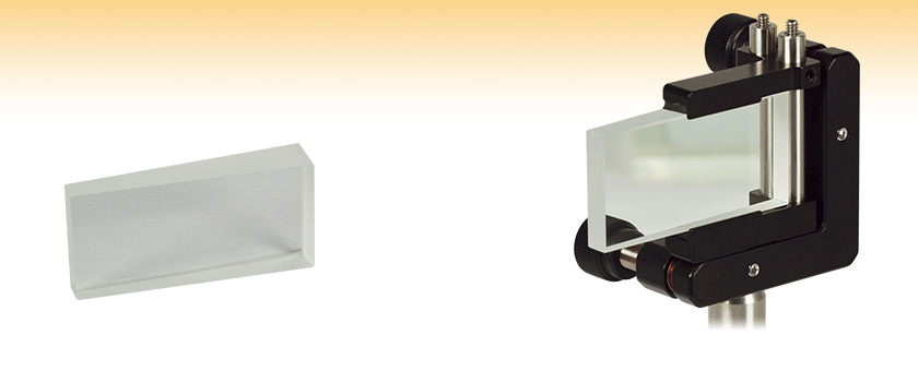
BSF2550
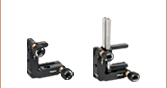
BSF2550 Mounted in a KM100C
Rectangular Optic Mount


Please Wait


Features
- Uncoated, Wedged Surface Creates Separated Attenuated Copies of an Incident Beam
- Ideal for High-Power Beam Attenuation
- Multiple Outputs may be Utilized for Different Experiments or Beam Monitoring
Thorlabs' Wedged Optical Beamsplitter is designed to separate a single input beam into multiple copies through successive reflections and refractions, as shown in the figure to the right. It is manufactured from UV fused silica, which offers transmission over the broad wavelength range from 185 nm to 2.1 µm. The wedge is formed using a 5° apex angle, which is designed to provide good separation between the multiple outputs. The rectangular shape allows for precise positioning of the output beams in a plane. It is 1" tall, ideal for mounting in our kinematic rectangular optic mounts or our fixed rectangular optic mount. The wedge is parallel to a 2" long surface, which allows for numerous copy beams to be created.
Upon each reflection and refraction, some of the input power will be lost; hence, the wedged beamsplitter may be used as an attenuator. Since the wedge is uncoated, the power handling will be increased above that for our neutral density filters. Successive transmitted or reflected beams might also be used for different experiments or multiple methods of beam monitoring, such as monitoring power fluctuations using a power meter or other detector, such as a camera or photodiode. Unused output beams can be blocked using a beam dump.
The angular deviation of the output beams may be easily calculated. For details, please see the Theory tab above. For more details on the theory of operation, please see the reference at the end of the Theory tab.

Click to Enlarge
Click Here for Raw Data
Plot of Transmission as a Function of Wavelength for a 10 mm Thick, Uncoated Sample of UV Fused Silica (Note: Surface Reflections are Included)
| Specifications | |
|---|---|
| Wedge Angle | 5° ± 3 arcmin |
| Size (L x H) | 50.8 mm x 25.4 mm (2.00" x 1.00") |
| Clear Aperture | 45.72 mm x 22.86 mm (1.80" x 0.90") |
| Surface Flatness | λ/4 @ 632 nm (per inch) |
| Surface Quality | 10-5 Scratch-Dig |
Dimensional Drawing of BSF2550 Wedged Plate Beamsplitter
Figure 1: Ray tracing and symbol definitions for the wedged beamsplitter.
Determining the Output Angles
By noting that the sum of the angles in a triangle is 180°, it can be shown that:
E1 = A + C,
G1 = 2E1 - C = C + 2A,
where the angles are defined in Figure 1. By continuing to apply these formulas to successive angles, it can be shown that:
GL = C + 2LA,
EL = C + (2L - 1)A
where L is any integer.
In figure 1, each ray output from the system is given a numeric designation; these will be referred to as the “output beam order.” The “even” orders are emitted from one side of the beamsplitter, and the “odd” orders are emitted from the other side, as indicated. Therefore there is a relationship between the beam order m and the angle indexing value L:
For odd values of m: m = 2L - 1
For even values of m: m = 2(L - 1).
Click to Enlarge
Figure 2: The index of refraction vs. wavelength for UV fused silica. Click here for an excel file containing this data.
The angles of refraction for the emerging beams may be calculated using Snell’s law from values of EL and GL. If the small angle approximation is used, then the sine of the angle is approximated by its value in radians, and it can be shown that:
FL = B + (2L - 1)nA
HL = B +2LnA,
where n is the index of refraction. The index of refraction depends on wavelength, a plot for UV Fused Silica is shown in Figure 2.
These expressions can be rewritten as a deviation from the incident beam, D. For the m = -1 beam, the deviation is:
D = 2B.
For the other odd orders, it is:
D = B + H(m+1)/2.
For the even orders, it is:
D = F(m/2)+1 - B - A
=(2m + 1)nA - A.
Remember that these values are approximations, and the real values may vary slightly due to the small angle approximation used in the derivation.
Other Considerations
It is worth noting that there will be a small polarization dependence on the intensity of the transmitted and reflected beams. However, if the angle of incidence is small, then the polarization effects will be minimized. It is also possible to calculate the attenuation experienced by each beam exiting the beamsplitter, the details of this calculation are in the reference.
Reference:
Beers, Y. "The Theory of the Optical Wedge Beam Splitter." NBS Monograph 146 (October 1974).
| Posted Comments: | |
Rosen Ivanov
(posted 2024-02-07 13:31:33.8) Dear Thorlabs Team,
I need a wedge similar to BSF2550 but with a more height at least around 30 mm (BSF2550 have 25.4mm height ), the other side could be the same 50.8mm or larger up to about 70mm . Wedge Angle could be from 3° to 5°. Surface Flatness and Surface Quality as for BSF2550.
Please tell me if you can offer bigger than BSF2550 wedge.
Thank you.
Best regards,
Rosen Ivanov jpolaris
(posted 2024-02-12 01:37:00.0) Thank you for contacting Thorlabs. Requests for custom items can be made by reaching out to us at our technical support email address that is local to your region. A complete list of our worldwide sales and technical support contacts can be found at the following link: https://www.thorlabs.com/supportcontact.cfm Chunyu Li
(posted 2023-06-06 13:46:37.097) Hello,
I am writing to ask about the power threshold of the beam splitter BSF2550 in terms of damage.
Thank you very much.
Best regards,
Chunyu cdolbashian
(posted 2023-06-12 01:41:57.0) Thank you for reaching out to us with this inquiry. We have not tested uncoated UVFS for damage threshold. Large peak powers from pulse lasers can cause localized heating within the substrate and cause the whole component to crack. Large CW power lasers can cause thermal lensing whereas the index of refraction changes as a function of temperature, thus altering the intended optical path. I have reached out to you directly to inquire about your source. user
(posted 2023-03-28 11:35:44.973) Can the power density of 500W/cm² be borne if the antireflection coating is plated at the right Angle? If possible, what is the price after coating? jgreschler
(posted 2023-03-29 03:17:49.0) Thank you for reaching out to Thorlabs. Damage thresholds vary from coating to coating, so I will need to reach out to you directly to discuss your application and find which one is right for you. Custom item quotations can be requested by contacting techsales@thorlabs.com jgreschler
(posted 2023-03-29 03:17:49.0) Thank you for reaching out to Thorlabs. Damage thresholds vary from coating to coating, so I will need to reach out to you directly to discuss your application and find which one is right for you. Custom item quotations can be requested by contacting techsales@thorlabs.com HCK user
(posted 2022-12-26 15:35:59.06) Is there any available data for polarization dependence feature of this product? cdolbashian
(posted 2022-12-28 10:34:32.0) Thank you for reaching out to us with this inquiry! Unfortunately, we have not tested the polarization dependence of this component explicitly, though we do have the following note on the "Theory" tab above: It is worth noting that there will be a small polarization dependence on the intensity of the transmitted and reflected beams. However, if the angle of incidence is small, then the polarization effects will be minimized. It is also possible to calculate the attenuation experienced by each beam exiting the beamsplitter, the details of this calculation are in the reference. Brian Villmoare
(posted 2022-04-13 01:26:17.44) Hi - is it possible to get these in specifically prescribed angles? Say, 15 degrees as the initial angle, giving also 30, 45, 60, etc.?
And what is the precision of these beamsplitters, in arcminutes/arcseconds?
Thanks!
cville1967@yahoo.com jgreschler
(posted 2022-04-22 09:05:25.0) Thank you for reaching out to Thorlabs. Custom configurations, dimensions, and wavelengths for our stock items can be requested by reaching out to techsupport@thorlabs.com. I have contacted you directly to further discuss this possibility. thumbd28455
(posted 2019-02-11 04:35:39.157) Could you make a BSF2550 plate with an AR coating & a Dielectric coating? nbayconich
(posted 2019-02-19 09:59:13.0) Thank you for contacting Thorlabs. We can provide AR coating for these beamsplitters. I will reach out to you directly to discuss our custom capabilities. micatlan
(posted 2017-09-12 13:07:36.913) Hi! could you make me a BSF2550 plate with smaller dimensions, 20mm x 20 mm?
Regards,
Michael Atlan tfrisch
(posted 2017-09-12 03:54:27.0) Hello, thank you for contacting Thorlabs. I will reach out to you about a quote. schumacher-PM
(posted 2015-04-01 10:08:17.04) Is there a ZEMAX-file available for this product? This would be very useful to simulate the behavior of my experiment. myanakas
(posted 2015-04-15 08:33:22.0) Response from Mike at Thorlabs: Thank you for your feedback. Zemax files have now been uploaded for our BSF2550 Wedged Plate Beamsplitter. They can be found by clicking on the red "Docs" icon next to the part number at the bottom of the page. I have also contacted you directly with these files. user
(posted 2015-01-28 13:28:11.09) Would be great if you offered this product but considerably thinner (<0.5 mm) at the tapered end. jlow
(posted 2015-02-03 10:26:40.0) Response from Jeremy at Thorlabs: We can offer custom solutions to this. Since you did not leave your contact information, can you contact us at techsupport@thorlabs.com for a quote please? 572595586
(posted 2014-07-10 09:59:05.81) Excuse me. This product is very useful for us. and there are some principle questions about how to use it. My question is that whether this product can separate the light according to the difference of wavelength. That is to say , I want to know whether each beam of light contains all wavelength of light or just with one wavelength.Thanks for offering me the answers. jlow
(posted 2014-08-19 08:37:43.0) Response from Jeremy at Thorlabs: Since different wavelength will see different refractive indices, multiple wavelengths would be separated by small angles. However, there are much better tools designed for wavelength separation such as dichroic mirrors, dispersive prisms, and gratings. If you would like to discuss about your application, please contact us at techsupport@thorlabs.com. |