 Products Home / Optical Elements / Optical Beamsplitters / Plate Beamsplitters / Polka Dot Beamsplitters
Polka Dot Beamsplitters
- Constant Reflection to Transmission Ratio Over Range
- 50:50 Beamsplitters
- Metal Coating is Relatively Insensitive to Incident Angle
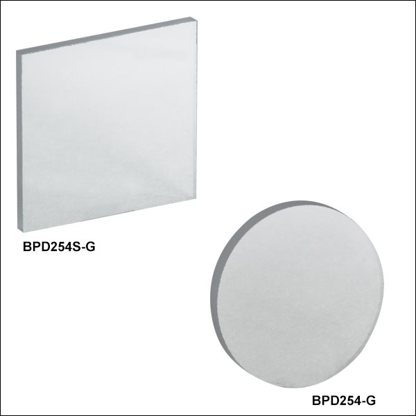
BPD254S-G
(1" x 1", B270 Glass Substrate)
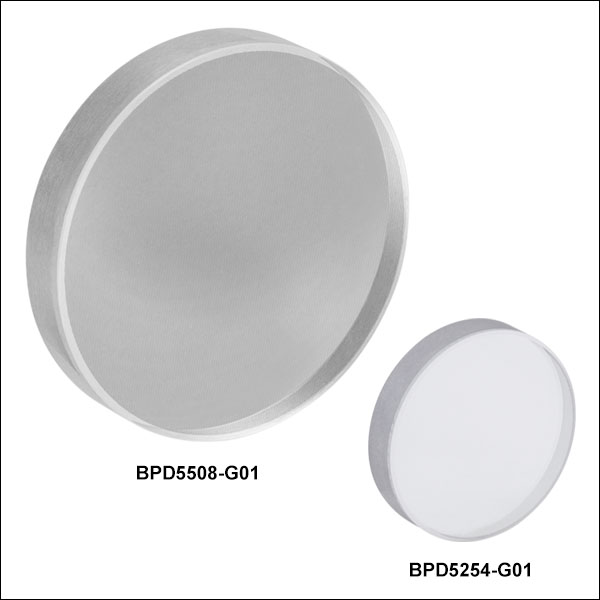
BPD5254-G01
(Ø1", CaF2 Substrate)
BPD508-FS
(Ø2", UVFS Substrate)


Please Wait
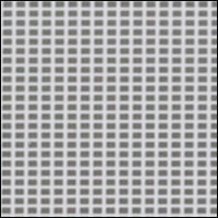
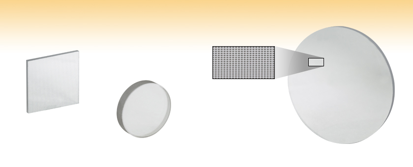
Detail of Aluminum Coating Pattern
Features
- 50:50 Beamsplitting Over Broad Transmission Range
- UVFS: 250 nm to 2.0 µm
- B270: 350 nm to 2.0 µm
- CaF2: 180 nm to 8.0 µm
- Three Substrate Options: UV Fused Silica, B270 Glass, or Calcium Fluoride (CaF2)
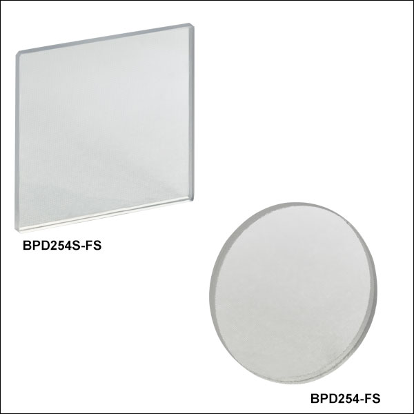
Thorlabs' 50:50 Polka Dot Beamsplitters offer a nearly constant beamsplitting ratio over their entire specified spectral range. They consist of a vacuum-deposited metal coating on one of three substrates: UV Fused Silica, B270, or CaF2. Due to their metal coatings, they can be used through a wide range of incident angles with only negligible changes to the reflected and transmitted intensity. To view wavelength- and angle-dependent reflection and transmission data, please click on the graph icons in the tables below.
The metal coating is applied in a regularly repeating array, which lends the beamsplitter its "polka dot" appearance, as shown to the right. Light is reflected by the metal-coated portion of the beamsplitter and transmitted through the uncoated portion of the beamsplitter. To maximize the reflected intensity, light should be incident on the coated side of the beamsplitter. The square dots have 0.0040" (100 µm) sides. The spacing between the dots is 0.0022" (56 µm) in all directions.

Polka dot beamsplitters are typically used at a 45° angle relative to the incident beam as shown in the diagram above. Our polka dot beamsplitters transmit 50% ± 5% when a beam is larger than 2 mm in diameter.
The Ø1" and Ø2" polka dot beamsplitters can be mounted into any of our Ø1" and Ø2" optic mounts, respectively. The 1" square beamsplitters can be held in a fixed filter mount like our DH1 Compact Dual Filter Holder.
Thorlabs also offers a family of plate beamsplitters with dielectric coatings. For more information on selecting a beamsplitter, please see the BS Selection Guide tab.
Beamsplitter Selection Guide
Thorlabs' portfolio contains many different kinds of beamsplitters, which can split beams by intensity or by polarization. We offer plate and cube beamsplitters, though other form factors exist, including pellicle and birefringent crystal. For an overview of the different types and a comparison of their features and applications, please see our overview. Many of our beamsplitters come in premounted or unmounted variants. Below is a complete listing of our beamsplitter offerings. To explore the available types, wavelength ranges, splitting/extinction ratios, transmission, and available sizes for each beamsplitter category, click More [+] in the appropriate row below.Plate Beamsplitters
| Non-Polarizing Plate Beamsplitters |
|---|


| Polarizing Plate Beamsplitters |
|---|
Cube Beamsplitters
| Non-Polarizing Cube Beamsplitters |
|---|


| Polarizing Cube and Polyhedron Beamsplitters |
|---|


Pellicle Beamsplitters
| Non-Polarizing Pellicle Beamsplitters |
|---|


Crystal Beamsplitters
| Polarizing Crystal Beamsplitters |
|---|
Other
| Other Beamsplitters |
|---|
| Posted Comments: | |
Liaoxin Sun
(posted 2023-09-11 11:53:05.427) I bought Polka-Dot beamsplitters, BPD5254-G01, for 457nm laser pump and infrared emission collection, an obviously diffraction occurs for 457nm, multiple laser spots appeared. Is this normal? cdolbashian
(posted 2023-09-25 10:08:25.0) Thank you for reaching out to us with this concern. I notice that the mirrored elements are separated by 50um for each element. This falls into a small enough separation to induce some effects of diffraction. The amplitude and spacing of fringes can be determined by using the J1 Bessel function and some algebra. I have contacted you directly with some supporting documentation. Alyssa Kostadinov
(posted 2021-11-30 08:34:09.963) Hi, do you have any data about the polarization dependency on reflection and transmission of s and p components at 45 degree AOI at 400-700nm range?
Thank you YLohia
(posted 2021-11-30 02:59:07.0) Hello, additional data can be requested by emailing techsupport@thorlabs.com. I have reached out to you directly with more information on the performance as a function of s and p polarization components. Hsiang-Chu Wang
(posted 2021-02-15 07:58:25.033) Dear Thorlab
I am interested in the component (BPD508-G), and wonder if it can be diced into a 25.2 mm x 35.6 mm x 1.5 mm.
Can you please also send me the spectrum of the transmission and reflection for both s- and p-polarized illumination.
Please contact me thanks. YLohia
(posted 2021-02-16 11:57:15.0) Hello, thank you for contacting Thorlabs. Custom optics can be requested by clicking on the "Request Quote" button above or by emailing techsupport@thorlabs.com. We will discuss the possibility of offering this directly. I have reached out to you with the transmission/reflection plots. Ivo Aubrecht
(posted 2019-06-18 08:27:22.74) Do you also sell beam splitters with uniform metallic coatings (no patterning)? with the same performance (approx. 50:50) in an angular range 5 - 45 deg? YLohia
(posted 2019-06-18 08:48:19.0) Hello, thank you for contacting Thorlabs. We will reach out to you directly to discuss the possibility of offering this item. nikita.levichev
(posted 2018-08-21 13:54:48.983) Hello! I want to use Polka-Dot beamsplitters for the process monitoring (VIS-NIR). Are there any distortions in image quality after such splitting? And what is the average size of aluminum coating parts? YLohia
(posted 2018-08-21 09:01:36.0) Hello, thank you for contacting Thorlabs. There are indeed distortions in image quality after splitting. The feature size is 100 um x 100 um with a 56 um spacing between the metal coated squares (for UVFS, B270, and CaF2 substrates). I will reach out to you directly to discuss your application further and suggest suitable alternatives based on your requirements. robert.woodward
(posted 2018-02-07 14:47:18.64) Please could you provide the polarisation dependence of this product (I'm particularly interested in: BPD5254-G01). How does this compare to your other mid-IR beamsplitters (and is there any information on damage thresholds too please?). Many thanks. YLohia
(posted 2018-03-29 01:14:12.0) Response from Yashasvi at Thorlabs USA: Hello, thank you for contacting Thorlabs. S-polarization state will impact the average reflectance and average transmission by roughly +5% and -5%, respectively. P-polarization state will impact the average reflectance and average transmission by roughly -5% and +5%, respectively. I will reach out to you directly with plots for comparison with other mid-IR beamsplitters. Unfortunately, we have not performed damage threshold tests for this product line as of now. An estimate for the damage threshold can be provided by looking up our general damage threshold for our aluminum coating (0.3 J/cm2 at 1064 nm, Ø1.00 mm pulsed beam, 10 ns pulses @ 10 Hz), but since we have not performed specific tests for this product line as of now, we advise to err on the side of caution. maxirossa
(posted 2017-10-03 07:19:25.47) What are the laser-induced damage thresholds of the polka dot beamsplitters, especially the BPD5254-G01 and the BPD254-FS? Thanks in advance. nbayconich
(posted 2017-10-05 01:05:37.0) Thank you for contacting Thorlabs. At the moment we have not tested these optics. I will reach out to you directly to discuss your application requirements of these polka dot beamsplitters. kaiqianglin
(posted 2017-06-14 05:03:42.573) Hey, do you have any data about the polarization dependency on reflection of s and p components at 45 degree incident? We want to use it as a non-polarizing beam splitter. Many thanks. nbayconich
(posted 2017-06-15 05:07:56.0) Thank you for contacting Thorlabs. There is some polarization dependency in these polka dot beamsplitters. I will contact you directly about our S and P polarization reflectivity & transmission measurements. Thorlabs
(posted 2010-11-29 14:23:17.0) Response from Javier at Thorlabs to bung: we do not have information regarding the dispersive properties of our polka dot beamsplitters. Also, I will check with our optics department regarding the details about the dot sizes and the spacing, and their relationship with the beam diameter, which is recommended to be limited to 2 mm at minimum. We will contact you directly with mnore information. bung
(posted 2010-11-22 23:20:49.0) Hi, I am concerned about the dispersive properties of the polka dots on the beam splitter. Moreover, I am concerned about the correlation between the dot sizes and the minimum beam size acceptable. Is it in fact possible to present some calculation data, as to why the dots are the size and spacing? Thank you. apalmentieri
(posted 2009-12-14 14:34:03.0) A response from Adam at Thorlabs, Inc: From your description, I believe you are asking about the dispersive properties of the AL coating in which case you will not see any dispersive effects from the AL coating. I will email you shortly to try and get more information about your setup to see if we can provide anymore information. gmp1g09
(posted 2009-12-14 12:28:09.0) Sorry, there was a misunderstanding. I meant spectral interference, not spatial interference. I mean, I dont care if the wavefront is spatially distorted and the two beams dont interfere spatially. The only think important for me is that each wavelenght of one broadband beam interfere with the same wavelenght of the other beam. Is it possible with polka dot? Thanks for your patience. Giorgio apalmentieri
(posted 2009-12-14 12:01:13.0) A response from Adam at Thorlabs: I would not recommend using the polka dot beamsplitter inside an interferometer. The polka dot beamsplitter splits the beam via small reflective AL squares on a transmissive substrate. These squares create a speckled beam pattern distorting the overall wavefront. This distorted wavefront is not suitabel for an interferometer. I would recommend looking at the cube or plate beamsplitters, BS013 or BSW10. gmp1g09
(posted 2009-12-12 14:48:04.0) Hello, please advise if "polka dot" BS can be used in an interferometer (either Michelson or Mach Zehender interferometers). In general I am looking for BS that has no (or low) polarisation sensitivity and very broad band (600nm up to 1600nm). I need that the two beams which combine each other in the interferometer would be allowed to correctly interfere in the polka dot beamsplitter/combiner. Is it ok the polka dot for generating interference between two beams?
Dr. Giorgio Ponzo
ORC (Optoelectronics Research Centre)
Southampton (UK) Tyler
(posted 2008-11-05 16:32:29.0) A response from Tyler at Thorlabs to boris_golberg: We dont currently have a standard product that will meet the specifications that you listed. A member of our technical support department will contact you to discuss your application and discuss the possibility of creating a custom part quote. Thank you for sending Thorlabs your product request. We love to hear about new products and when possible we add them to our product line so that they become a standard product with same-day shipping availability. boris_golberg
(posted 2008-10-27 02:54:04.0) Hello,
please advise if "polka dot" BS can be use for imaging application (microscope).
Ratio I need T/R = 10/90, imaging use reflection part.
In general I am looking for BS that has no (or low) polarisation sensitivity @ 193 nm with T/R = 10/90.
Please advise |

 Zoom
Zoom| Specifications | |
|---|---|
| Available Sizes | Ø1", Ø2", or 1" Square |
| Beamsplitting Ratio | 50% ± 5% |
| Minimum Beam Diameter for 50/50 Split | 2 mm |
| Material | UV Fused Silica |
| Wavelength Range | 250 nm - 2.0 µm |
| Coating Pattern | Square-Coated Apertures 0.0040" (100 µm) Sides, 0.0022" (56 µm) Spacing |
| Clear Aperture | >90% Diameter (Round Optics) >90% Length and Height (Square Optics) |
| Thickness | 1.5 mm (Nominal) |
| Dimensional Tolerance | +0.0 / -0.5 mm |
| Angle of Incidence | 0 to 45° |
These Polka Dot Beamsplitters are made from UV Fused Silica (UVFS) and provide high transmission over the 250 nm - 2.0 µm spectral range. They can be used from 0 to 45° AOI with only negligible changes to the reflected and transmitted intensity. Light should be incident on the aluminum-coated side to maximize the reflected intensity.
| Transmission and Reflectance Dataa | |
|---|---|
| 0° and 8° AOIb |  |
| 45° AOI |  |

 Zoom
Zoom| Specifications | |
|---|---|
| Available Sizes | Ø1", Ø2", or 1" Square |
| Beamsplitting Ratio | 50% ± 5% |
| Minimum Beam Diameter for 50/50 Split | 2 mm |
| Material | B270 |
| Wavelength Range | 350 nm - 2.0 µm |
| Coating Pattern | Square-Coated Apertures 0.0040" (100 µm) Sides, 0.0022" (56 µm) Spacing |
| Clear Aperture | >90% Diameter (Round Optics) >90% Length and Height (Square Optics) |
| Thickness | 1.5 mm (Nominal) |
| Dimensional Tolerance | +0.0 / -0.5 mm |
| Angle of Incidence | 0 to 45° |
These Polka Dot Beamsplitters are made from B270 glass and provide high transmission over the 350 nm - 2.0 µm spectral range. They can be used from 0 to 45° AOI with only negligible changes to the reflected and transmitted intensity. Light should be incident on the aluminum-coated side to maximize the reflected intensity.
| Transmission and Reflectance Dataa | |
|---|---|
| 0° and 8° AOIb |  |
| 45° AOI |  |

 Zoom
Zoom
| Specifications | |
|---|---|
| Available Sizes | Ø1" or Ø2" |
| Beamsplitting Ratio | 50% ± 5% |
| Minimum Beam Diameter for 50/50 Split | 2 mm |
| Material | CaF2 |
| Wavelength Range | 0.18 - 8.0 µm |
| Coating Pattern | Square-Coated Apertures 0.0040" (100 µm) Sides, 0.0022" (56 µm) Spacing |
| Clear Aperture | >90% Diameter |
| Surface Flatness | λ/4 at 632.8 nm, Over Clear Aperture |
| Surface Quality | 60-40 Scratch-Dig |
| Thickness | 5 ± 0.3 mm (Ø1" Optics) 8.0 mm (Ø2" Optics) |
| Diameter Tolerance | +0.0 / -0.2 mm |
| Angle of Incidence | 0 to 45° |
These Polka Dot Beamsplitters are made from Calcium Fluoride (CaF2) and provide high transmission over the 180 nm - 8.0 µm spectral range. They can be used from 0 to 45° AOI with only negligible changes to the reflected and transmitted intensity. Light should be incident on the aluminum-coated side to maximize the reflected intensity.
| Transmission and Reflectance Dataa | |
|---|---|
| 0° and 12° AOIb |  |
| 45° AOI |  |