 Products Home / Optical Elements / Optical Beamsplitters / Plate Beamsplitters / Non-Polarizing Plate Beamsplitters / UV Fused Silica Broadband Plate Beamsplitters (Coating: 1.2 - 1.6 µm)
UV Fused Silica Broadband Plate Beamsplitters (Coating: 1.2 - 1.6 µm)
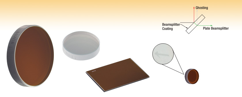
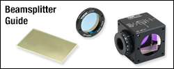
- Beamsplitter Coating for the 1.2 - 1.6 µm Range at 45° Incidence
- 10:90, 30:70, 50:50, 70:30, or 90:10 Split Ratios
- Ø1/2", Ø1", 25 mm x 36 mm, & Ø2" Sizes
BSW18
(Ø2")
BSS12
(Ø1")
BSW12R
(25 mm x 36 mm)
BSW06
(Ø1/2")
Engraved Arrow Points
in the Direction of
Light Transmission


Please Wait
| Plate Beamsplitter Selection Guide | |
|---|---|
| Substrate | Beamsplitter Coating |
| UV Fused Silica | 250 - 450 nm |
| 350 - 1100 nm | |
| 400 - 700 nm | |
| 532 nm and 1064 nm | |
| 600 - 1700 nm | |
| 700 - 1100 nm | |
| 1.2 - 1.6 µm | |
| IR Fused Silica | 0.9 - 2.6 µm |
| Calcium Fluoride | 1 - 6 μm |
| 2 - 8 μm | |
| Zinc Selenide | 1 - 12 μm |
| 7 - 14 μm | |

Features
- Beamsplitter Coating on Front Surface: 1.2 - 1.6 µm
- Five Split Ratios Available (R:T) Optimized for a 45° Angle of Incidence (AOI)
- 10:90
- 30:70
- 50:50
- 70:30
- 90:10
- Antireflection (AR) Coating on Back Surface: 1.2 - 1.6 µm
- Ø1/2", Ø1", 25 mm x 36 mm, and Ø2" Versions Available
- UV Fused Silica Substrate (Transmission Curve; Detailed Substrate Information)
- 30 arcmin Wedged Back Surface on Round Beamsplitters Minimizes Ghosting
Thorlabs' UV Fused Silica Broadband Beamsplitters provide split ratios of 10:90, 30:70, 50:50, 70:30, or 90:10 and have a dielectric beamsplitter coating ideal for the 1.2 - 1.6 µm range deposited on the front surface. The dielectric coating is optimized for a 45° angle of incidence and provides long-term stability. These beamsplitters come in Ø1/2", Ø1", 25 mm x 36 mm, and Ø2" sizes.
These plate beamsplitters are fabricated from UV-grade fused silica, which offers high transmission deep into the UV, good homogeneity, and a lower coefficient of thermal expansion than N-BK7. In addition, UV fused silica exhibits virtually no laser-induced fluorescence (as measured at 193 nm), making it an ideal choice for applications from the UV to the near IR.
To help reduce unwanted interference effects (e.g., ghost images) caused by the interaction of light reflected from the front and back surfaces of the optic, all of these plate beamsplitters have an antireflection (AR) coating deposited onto the back surface. This coating is designed for the same operating wavelength range as the beamsplitter coating on the front surface. Approximately 4% of the light incident at 45° on an uncoated substrate will be reflected; by applying an AR coating to the back side of the beamsplitter, this percentage is reduced to an average of less than 1% over the entire operating range of the coating. In addition to this feature, the back of all of our round broadband plate beamsplitters has a 30 arcmin wedge; therefore, the fraction of light that does get reflected from this AR-coated surface will diverge.
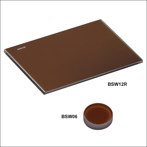
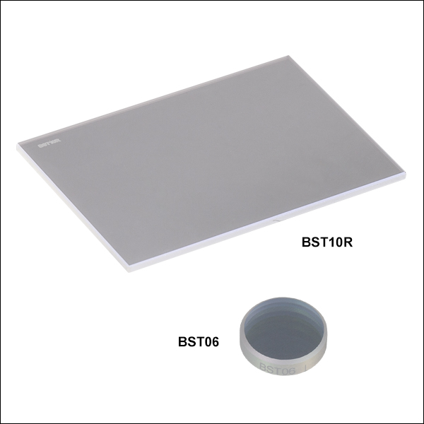
The edge of each round plate beamsplitter is engraved with the item number and an arrow pointing to the AR-coated, wedged surface (see the Drawings tab in the blue info icons below for an illustration). Our rectangular beamsplitters, which have been designed for mounting in microscopy filter cubes, feature the engraved item number on the side with the beamsplitter coating, making it easy to differentiate between the front and back surfaces.
Thorlabs offers three types of non-polarizing beamsplitters: Non-Polarizing Beamsplitting Cubes (mounted and unmounted), Pellicle Beamsplitters (mounted and unmounted), and the Plate Beamsplitters (see below and selection guide above). For a direct comparison of the performance of our non-polarizing beamsplitting cube, plate, and pellicle at 633 nm, see the Lab Facts tab.
Thorlabs Lab Fact: Beamsplitter Package Matters
We present laboratory measurements of the polarization angle, split ratio, and total throughput power of a beam transmitted through Thorlabs plate, cube, and pellicle beamsplitters. While all non-polarizing beamsplitters function similarly, the exact performance is different for different types of beamsplitter. Each type of beamsplitter contains its own advantages and disadvantages compared to other types of beamsplitters. Appropriate choice of beamsplitter is essential to sensitive experimental systems. We present a complete analysis and comparison of optical parameters for three common types of non-polarizing beamsplitters.
For our experiment we used the former generation HRS015 stabilized HeNe laser (replaced by the HRS015B) as the light source for our investigation. A linear polarizer is used to set the laser beam's polarization axis to 45° in order to provide equal s- and p-polarized light incident on the beamsplitter. The beamsplitter under investigation was then placed in the beampath, and its split beams directed to appropriate detectors. The total power though the optic, polarization states, split ratios, and angle of incidence effects were investigated under this configuration.

The plots below summarize the measured results for all three types of beamsplitters. From these graphs the performance of each optic can be easily compared to one another. The bottom left plot summarizes the results for the total power throughput for each optic. The total power throughput is measured as the fraction of input power. While the plate and pellicle beamsplitters perform rather similarly, the cube shows signs of absorption inside the optic. Additionally, this plot shows the relative insensitivity of throughput power to angle of incidence. The bottom middle graph summarizes the results for the output polarization angle for each optic. The cube shows the most similar polarization angles between the reflected and transmitted beams, with the plate producing the largest difference in polarization between beams. The bottom right plot summarizes the results for the split ratio, as a fraction of input power, for the beamsplitters. Here it can be shown that the plate beamsplitter demonstrates the most ideal for 50/50 power splitting. For details on the experimental setup employed and the results summarized here, please click here.
| Damage Threshold Specifications | |
|---|---|
| Coating Designation (Item # Prefix) |
Damage Threshold |
| BSW- | 4 J/cm2 (810 nm, 10 ns, 10 Hz, Ø0.157 mm) |
Damage Threshold Data for Thorlabs' 1.2 - 1.6 µm AR-Coated 50:50 UV Fused Silica Beamsplitters
The specifications to the right are measured data for Thorlabs' 1.2 - 1.6 µm AR-coated UV fused silica 50:50 beamsplitters. Damage threshold specifications are constant for all 50:50 AR-coated 1.2 - 1.6 µm UV fused silica beamsplitters.
Laser Induced Damage Threshold Tutorial
The following is a general overview of how laser induced damage thresholds are measured and how the values may be utilized in determining the appropriateness of an optic for a given application. When choosing optics, it is important to understand the Laser Induced Damage Threshold (LIDT) of the optics being used. The LIDT for an optic greatly depends on the type of laser you are using. Continuous wave (CW) lasers typically cause damage from thermal effects (absorption either in the coating or in the substrate). Pulsed lasers, on the other hand, often strip electrons from the lattice structure of an optic before causing thermal damage. Note that the guideline presented here assumes room temperature operation and optics in new condition (i.e., within scratch-dig spec, surface free of contamination, etc.). Because dust or other particles on the surface of an optic can cause damage at lower thresholds, we recommend keeping surfaces clean and free of debris. For more information on cleaning optics, please see our Optics Cleaning tutorial.
Testing Method
Thorlabs' LIDT testing is done in compliance with ISO/DIS 11254 and ISO 21254 specifications.
First, a low-power/energy beam is directed to the optic under test. The optic is exposed in 10 locations to this laser beam for 30 seconds (CW) or for a number of pulses (pulse repetition frequency specified). After exposure, the optic is examined by a microscope (~100X magnification) for any visible damage. The number of locations that are damaged at a particular power/energy level is recorded. Next, the power/energy is either increased or decreased and the optic is exposed at 10 new locations. This process is repeated until damage is observed. The damage threshold is then assigned to be the highest power/energy that the optic can withstand without causing damage. A histogram such as that below represents the testing of one BB1-E02 mirror.

The photograph above is a protected aluminum-coated mirror after LIDT testing. In this particular test, it handled 0.43 J/cm2 (1064 nm, 10 ns pulse, 10 Hz, Ø1.000 mm) before damage.

| Example Test Data | |||
|---|---|---|---|
| Fluence | # of Tested Locations | Locations with Damage | Locations Without Damage |
| 1.50 J/cm2 | 10 | 0 | 10 |
| 1.75 J/cm2 | 10 | 0 | 10 |
| 2.00 J/cm2 | 10 | 0 | 10 |
| 2.25 J/cm2 | 10 | 1 | 9 |
| 3.00 J/cm2 | 10 | 1 | 9 |
| 5.00 J/cm2 | 10 | 9 | 1 |
According to the test, the damage threshold of the mirror was 2.00 J/cm2 (532 nm, 10 ns pulse, 10 Hz, Ø0.803 mm). Please keep in mind that these tests are performed on clean optics, as dirt and contamination can significantly lower the damage threshold of a component. While the test results are only representative of one coating run, Thorlabs specifies damage threshold values that account for coating variances.
Continuous Wave and Long-Pulse Lasers
When an optic is damaged by a continuous wave (CW) laser, it is usually due to the melting of the surface as a result of absorbing the laser's energy or damage to the optical coating (antireflection) [1]. Pulsed lasers with pulse lengths longer than 1 µs can be treated as CW lasers for LIDT discussions.
When pulse lengths are between 1 ns and 1 µs, laser-induced damage can occur either because of absorption or a dielectric breakdown (therefore, a user must check both CW and pulsed LIDT). Absorption is either due to an intrinsic property of the optic or due to surface irregularities; thus LIDT values are only valid for optics meeting or exceeding the surface quality specifications given by a manufacturer. While many optics can handle high power CW lasers, cemented (e.g., achromatic doublets) or highly absorptive (e.g., ND filters) optics tend to have lower CW damage thresholds. These lower thresholds are due to absorption or scattering in the cement or metal coating.

LIDT in linear power density vs. pulse length and spot size. For long pulses to CW, linear power density becomes a constant with spot size. This graph was obtained from [1].

Pulsed lasers with high pulse repetition frequencies (PRF) may behave similarly to CW beams. Unfortunately, this is highly dependent on factors such as absorption and thermal diffusivity, so there is no reliable method for determining when a high PRF laser will damage an optic due to thermal effects. For beams with a high PRF both the average and peak powers must be compared to the equivalent CW power. Additionally, for highly transparent materials, there is little to no drop in the LIDT with increasing PRF.
In order to use the specified CW damage threshold of an optic, it is necessary to know the following:
- Wavelength of your laser
- Beam diameter of your beam (1/e2)
- Approximate intensity profile of your beam (e.g., Gaussian)
- Linear power density of your beam (total power divided by 1/e2 beam diameter)
Thorlabs expresses LIDT for CW lasers as a linear power density measured in W/cm. In this regime, the LIDT given as a linear power density can be applied to any beam diameter; one does not need to compute an adjusted LIDT to adjust for changes in spot size, as demonstrated by the graph to the right. Average linear power density can be calculated using the equation below.

The calculation above assumes a uniform beam intensity profile. You must now consider hotspots in the beam or other non-uniform intensity profiles and roughly calculate a maximum power density. For reference, a Gaussian beam typically has a maximum power density that is twice that of the uniform beam (see lower right).
Now compare the maximum power density to that which is specified as the LIDT for the optic. If the optic was tested at a wavelength other than your operating wavelength, the damage threshold must be scaled appropriately. A good rule of thumb is that the damage threshold has a linear relationship with wavelength such that as you move to shorter wavelengths, the damage threshold decreases (i.e., a LIDT of 10 W/cm at 1310 nm scales to 5 W/cm at 655 nm):

While this rule of thumb provides a general trend, it is not a quantitative analysis of LIDT vs wavelength. In CW applications, for instance, damage scales more strongly with absorption in the coating and substrate, which does not necessarily scale well with wavelength. While the above procedure provides a good rule of thumb for LIDT values, please contact Tech Support if your wavelength is different from the specified LIDT wavelength. If your power density is less than the adjusted LIDT of the optic, then the optic should work for your application.
Please note that we have a buffer built in between the specified damage thresholds online and the tests which we have done, which accommodates variation between batches. Upon request, we can provide individual test information and a testing certificate. The damage analysis will be carried out on a similar optic (customer's optic will not be damaged). Testing may result in additional costs or lead times. Contact Tech Support for more information.
Pulsed Lasers
As previously stated, pulsed lasers typically induce a different type of damage to the optic than CW lasers. Pulsed lasers often do not heat the optic enough to damage it; instead, pulsed lasers produce strong electric fields capable of inducing dielectric breakdown in the material. Unfortunately, it can be very difficult to compare the LIDT specification of an optic to your laser. There are multiple regimes in which a pulsed laser can damage an optic and this is based on the laser's pulse length. The highlighted columns in the table below outline the relevant pulse lengths for our specified LIDT values.
Pulses shorter than 10-9 s cannot be compared to our specified LIDT values with much reliability. In this ultra-short-pulse regime various mechanics, such as multiphoton-avalanche ionization, take over as the predominate damage mechanism [2]. In contrast, pulses between 10-7 s and 10-4 s may cause damage to an optic either because of dielectric breakdown or thermal effects. This means that both CW and pulsed damage thresholds must be compared to the laser beam to determine whether the optic is suitable for your application.
| Pulse Duration | t < 10-9 s | 10-9 < t < 10-7 s | 10-7 < t < 10-4 s | t > 10-4 s |
|---|---|---|---|---|
| Damage Mechanism | Avalanche Ionization | Dielectric Breakdown | Dielectric Breakdown or Thermal | Thermal |
| Relevant Damage Specification | No Comparison (See Above) | Pulsed | Pulsed and CW | CW |
When comparing an LIDT specified for a pulsed laser to your laser, it is essential to know the following:

LIDT in energy density vs. pulse length and spot size. For short pulses, energy density becomes a constant with spot size. This graph was obtained from [1].
- Wavelength of your laser
- Energy density of your beam (total energy divided by 1/e2 area)
- Pulse length of your laser
- Pulse repetition frequency (prf) of your laser
- Beam diameter of your laser (1/e2 )
- Approximate intensity profile of your beam (e.g., Gaussian)
The energy density of your beam should be calculated in terms of J/cm2. The graph to the right shows why expressing the LIDT as an energy density provides the best metric for short pulse sources. In this regime, the LIDT given as an energy density can be applied to any beam diameter; one does not need to compute an adjusted LIDT to adjust for changes in spot size. This calculation assumes a uniform beam intensity profile. You must now adjust this energy density to account for hotspots or other nonuniform intensity profiles and roughly calculate a maximum energy density. For reference a Gaussian beam typically has a maximum energy density that is twice that of the 1/e2 beam.
Now compare the maximum energy density to that which is specified as the LIDT for the optic. If the optic was tested at a wavelength other than your operating wavelength, the damage threshold must be scaled appropriately [3]. A good rule of thumb is that the damage threshold has an inverse square root relationship with wavelength such that as you move to shorter wavelengths, the damage threshold decreases (i.e., a LIDT of 1 J/cm2 at 1064 nm scales to 0.7 J/cm2 at 532 nm):

You now have a wavelength-adjusted energy density, which you will use in the following step.
Beam diameter is also important to know when comparing damage thresholds. While the LIDT, when expressed in units of J/cm², scales independently of spot size; large beam sizes are more likely to illuminate a larger number of defects which can lead to greater variances in the LIDT [4]. For data presented here, a <1 mm beam size was used to measure the LIDT. For beams sizes greater than 5 mm, the LIDT (J/cm2) will not scale independently of beam diameter due to the larger size beam exposing more defects.
The pulse length must now be compensated for. The longer the pulse duration, the more energy the optic can handle. For pulse widths between 1 - 100 ns, an approximation is as follows:

Use this formula to calculate the Adjusted LIDT for an optic based on your pulse length. If your maximum energy density is less than this adjusted LIDT maximum energy density, then the optic should be suitable for your application. Keep in mind that this calculation is only used for pulses between 10-9 s and 10-7 s. For pulses between 10-7 s and 10-4 s, the CW LIDT must also be checked before deeming the optic appropriate for your application.
Please note that we have a buffer built in between the specified damage thresholds online and the tests which we have done, which accommodates variation between batches. Upon request, we can provide individual test information and a testing certificate. Contact Tech Support for more information.
[1] R. M. Wood, Optics and Laser Tech. 29, 517 (1998).
[2] Roger M. Wood, Laser-Induced Damage of Optical Materials (Institute of Physics Publishing, Philadelphia, PA, 2003).
[3] C. W. Carr et al., Phys. Rev. Lett. 91, 127402 (2003).
[4] N. Bloembergen, Appl. Opt. 12, 661 (1973).
| Posted Comments: | |
A Peterson
(posted 2024-03-07 11:13:17.547) Hi, I'm looking for information on the R:T ratio changes with angle of incidence (specifically between 0 and 45 degrees) for BSN18, BSS18, BSW18, BST18, and BSX18. Is this data available? Thanks. cdolbashian
(posted 2024-03-18 04:46:33.0) Thank you for reaching out to us with this request! Unfortunately, we do not have all the data you requested, for all angles and wavelengths, at this time. However, we still have a fair amount, and I have provided you with as much of the extended data as we currently have available. Tahlia MacGillivray
(posted 2023-08-07 03:31:19.247) Hi thorlabs.com admin, Thanks for the informative and well-written post! cdolbashian
(posted 2023-08-16 11:26:00.0) Thank you for your feedback! Klaus Yang
(posted 2023-03-09 02:37:54.2) To the thorlabs.com administrator, Your posts are always thought-provoking and inspiring. jdelia
(posted 2023-03-09 10:33:00.0) Thank you for contacting Thorlabs, and for providing this feedback. Benjamin Lang
(posted 2021-12-20 10:10:39.297) As "Laurent L" (posted 2019-04-25 11:48:59.733) I am also interested in the reflectance/transmittance behavior of the beamsplitters at 0° incidence. Both, the BBAR as well as the beamsplitter coating data for the BSX and BST splitters would be interesting to us. Many thanks in advance! cdolbashian
(posted 2022-01-06 11:37:07.0) Thank you for reaching out to us Benjamin. I have reached out to you directly with this data. Sakees Chidambaram
(posted 2020-11-30 07:11:41.363) Hi, Is there any temperature dependence on non-polarizing plate beam-splitters (UV fused silica, 1550 nm)? What is the typical working temperature range? Can you also provide a detailed operating/ environmental specification for the same?
many thanks! YLohia
(posted 2020-12-14 01:52:13.0) Hello, thank you for contacting Thorlabs. While we don't have formal operating temperature ranges spec'd for these, we do expect these to be fine for your -20 C to +55 C application. I have reached out to you directly to discuss further. Laurent L
(posted 2019-04-25 11:48:59.733) What is the behavior of those beamsplitters at 0° incidence? Thanks YLohia
(posted 2019-04-25 04:25:26.0) Thank you for contacting Thorlabs. We will reach out to you directly with transmission information at 0 deg AOI. jlow
(posted 2012-08-01 17:06:00.0) Response from Jeremy at Thorlabs: Thank you for this inquiry. I will get in contact with you directly on the possibility of making this custom. jikim
(posted 2012-07-31 14:18:33.0) I would like to ask the availability of plate beam splitters with 6 mm diameter, 3 mm thickness, and 10:90 (T:R). The disired quantity is 3 pieces.
Could you also provide me a cube type BS with 5 mm^3 and 10:90 (T:R)?
Best Regards tcohen
(posted 2012-04-05 15:13:00.0) Response from Tim at Thorlabs: Our online specifications consider incident light on the coated side. You may experience slightly different transmission/reflection as the AOI changes due to refraction through the substrate. Also, please note that the uncoated surface has a slight wedge to diminish ghosting. I have contacted you to discuss this further. Junweiwei
(posted 2012-03-22 15:35:23.0) Can I use the plate beam splitter BST12 in the Michelson interferometer setup where the beam will come in 2 directions, such that there are 2 beams (one reflection and one transmission) in both out-going directions? Will the two beams well-overlapped? jjurado
(posted 2011-02-02 15:26:00.0) Response from Javier at Thorlabs to qihong.wu: Thank you very much for submitting your inquiry. We will send you a plot with information about the phase shift generated by the BSW06. We will also post this information on the web shortly. qihong.wu
(posted 2011-01-25 07:35:56.0) BSW06
Could you provide the phase shift of P and S under 45 degree for BSW Thorlabs
(posted 2010-07-22 11:58:18.0) Response from Javier at Thorlabs to Matthieu: Thank you for your feedback. We can certainly offer a BSW20 beamsplitter with a thickness of 3 mm. However, keep in mind that the surface flatness would be compromised (~1/6 wave). I will contact you directly with more details. Matthieu.Refregiers
(posted 2010-07-22 11:47:28.0) Dear Sir/Madam,
Is it possible to obtain a BSW20 with a 3mm thickness or a 1 inch diameter BSW19 ? Adam
(posted 2010-05-17 15:49:50.0) A response from Adam at Thorlabs to Melsscal: I will contact you directly to get information about the application and provide you with a quote. melsscal
(posted 2010-05-17 14:05:01.0) We need 0.5" Dia :
1>Beam splitter for 780 nm beam (simple circular disc type) R/T =10/90 (3 pieces)
2>Beam splitter for 780 nm beam (simple circular disc type) R/T =30/70 (3 pieces)
Is it possible to get a custom quote for same ?
Regards A.K.Bose ghegenbart
(posted 2008-09-03 02:13:46.0) Comment from Gerald Hegenbart, Thorlabs Germany:
The spec for the flatness of both surfaces is lambda/10 at 633 nm over the clear aperture. Triggered by your inquiry the wavefront error in transmission has been measured by our optics department on an item out of the actual production. It was determined to be about 0.17 lambda peak-to-valley (VP) and about 0.03 root-mean-square (rms). I will email the plots to you.
Custom coatings are available on demand. To understand your needs, clarify the details, and agree on a path forward I will contact you directly. michael.deyerler
(posted 2008-08-28 03:44:53.0) Hello,
we purchased the BSW14 beamsplitter plate.
Id like to know the
- wavefront error in transmission @ 45°
- the flattness of the rear surface.
- is this type available in R/T=25%/75%
I appreciate your quick reply.
best regards
Michael Deyerler
P.S. A similar, not completed feedback was submitted on failure. Please discard it. |
Beamsplitter Selection Guide
Thorlabs' portfolio contains many different kinds of beamsplitters, which can split beams by intensity or by polarization. We offer plate and cube beamsplitters, though other form factors exist, including pellicle and birefringent crystal. For an overview of the different types and a comparison of their features and applications, please see our overview. Many of our beamsplitters come in premounted or unmounted variants. Below is a complete listing of our beamsplitter offerings. To explore the available types, wavelength ranges, splitting/extinction ratios, transmission, and available sizes for each beamsplitter category, click More [+] in the appropriate row below.Plate Beamsplitters
| Non-Polarizing Plate Beamsplitters |
|---|


| Polarizing Plate Beamsplitters |
|---|
Cube Beamsplitters
| Non-Polarizing Cube Beamsplitters |
|---|


| Polarizing Cube and Polyhedron Beamsplitters |
|---|


Pellicle Beamsplitters
| Non-Polarizing Pellicle Beamsplitters |
|---|


Crystal Beamsplitters
| Polarizing Crystal Beamsplitters |
|---|
Other
| Other Beamsplitters |
|---|
 Plate Beamsplitters")
 Zoom
Zoom

Click for Raw Data in the 1.0 - 1.8 μm Range
Transmission and reflectance data for the broadband plate beamsplitters coated for 1.2 - 1.6 µm was obtained for a 45° angle of incidence (AOI). The shaded region denotes the stated beamsplitter coating range. Reflectance and transmission were measured separately using a Perkin Elmer Lambda 950 UV/VIS/NIR spectrophotometer with a calcite polarizer attachment.
| Item # | Size | Thickness | Wedge Angle | Split Ratio (R:T) | Overall Performance | Info |
|---|---|---|---|---|---|---|
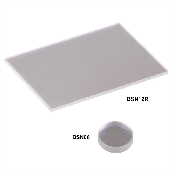
| BSN06 | Ø1/2" | 3 mm | 30 arcmin | 10:90 | Tabs = 90 ± 8%, Rabs = 10 ± 8%, Tabs + Rabs > 99% |Ts - Tp| < 35% and |Rs - Rp| < 35%, 45° AOI |
|
| BSN12 | Ø1" | 5 mm | 30 arcmin | 10:90 | ||
| BSN12R | 25 mm x 36 mm | 1 mm | No Wedge | 10:90 | ||
| BSN18 | Ø2" | 8 mm | 30 arcmin | 10:90 |
 Plate Beamsplitters")
 Zoom
Zoom
Click for Raw Data in the 300 - 2500 nm Range
Transmission and reflectance data for the broadband plate beamsplitters coated for 1.2 - 1.6 µm was obtained for a 45° angle of incidence (AOI). The shaded region denotes the stated beamsplitter coating range. Reflectance and transmission were measured separately using a Perkin Elmer Lambda 950 UV/VIS/NIR spectrophotometer with a calcite polarizer attachment.
| Item # | Size | Thickness | Wedge Angle | Split Ratio (R:T) | Overall Performance | Info |
|---|---|---|---|---|---|---|
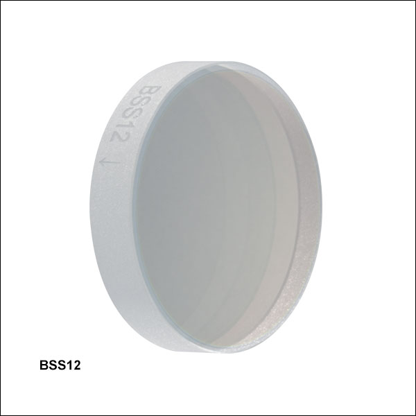
| BSS06 | Ø1/2" | 3 mm | 30 arcmin | 30:70 | Tabs = 70 ± 8%, Rabs = 30 ± 8%, Tabs + Rabs > 99% |Ts - Tp| < 35% and |Rs - Rp| < 35%, 45° AOI |
|
| BSS12 | Ø1" | 5 mm | 30 arcmin | 30:70 | ||
| BSS12R | 25 mm x 36 mm | 1 mm | No wedge | 30:70 | ||
| BSS18 | Ø2" | 8 mm | 30 arcmin | 30:70 |
 Plate Beamsplitters")
 Zoom
Zoom
Click for Raw Data in the 300 - 2500 nm Range
Transmission and reflectance data for the broadband plate beamsplitters coated for 1.2 - 1.6 µm was obtained for a 45° angle of incidence (AOI). The shaded region denotes the stated beamsplitter coating range. Reflectance and transmission were measured separately using a Perkin Elmer Lambda 950 UV/VIS/NIR spectrophotometer with a calcite polarizer attachment.
| Item # | Size | Thickness | Wedge Angle | Split Ratio (R:T) | Overall Performance | Info |
|---|---|---|---|---|---|---|
| BSW06 | Ø1/2" | 3 mm | 30 arcmin | 50:50 | Tabs = 50 ± 8%, Rabs = 50 ± 8%, Tabs + Rabs > 99% |Ts - Tp| < 15% and |Rs - Rp| < 15%, 45° AOI |
|
| BSW12 | Ø1" | 5 mm | 30 arcmin | 50:50 | ||
| BSW12R | 25 mm x 36 mm | 1 mm | No Wedge | 50:50 | ||
| BSW18 | Ø2" | 8 mm | 30 arcmin | 50:50 |
 Plate Beamsplitters")
 Zoom
Zoom

Click for Raw Data in the 300 - 2500 nm Range
Transmission and reflectance data for the broadband plate beamsplitters coated for 1.2 - 1.6 µm was obtained for a 45° angle of incidence (AOI). The shaded region denotes the stated beamsplitter coating range. Reflectance and transmission were measured separately using a Perkin Elmer Lambda 950 UV/VIS/NIR spectrophotometer with a calcite polarizer attachment.
| Item # | Size | Thickness | Wedge Angle | Split Ratio (R:T) | Overall Performance | Info |
|---|---|---|---|---|---|---|
| BST06 | Ø1/2" | 3 mm | 30 arcmin | 70:30 | Tabs = 30 ± 8%, Rabs = 70 ± 8%, Tabs + Rabs > 99% |Ts - Tp| < 35% and |Rs - Rp| < 35%, 45° AOI |
|
| BST12 | Ø1" | 5 mm | 30 arcmin | 70:30 | ||
| BST12R | 25 mm x 36 mm | 1 mm | No Wedge | 70:30 | ||
| BST18 | Ø2" | 8 mm | 30 arcmin | 70:30 |
 Plate Beamsplitters")
 Zoom
Zoom

Click for Raw Data in the 300 - 2500 nm Range
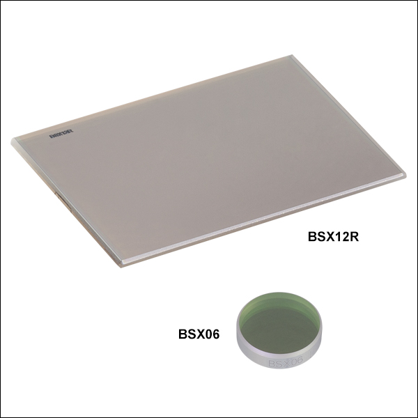
Transmission and reflectance data for the broadband plate beamsplitters coated for 1.2 - 1.6 µm was obtained for a 45° angle of incidence (AOI). The shaded region denotes the stated beamsplitter coating range. Reflectance and transmission were measured separately using a Perkin Elmer Lambda 950 UV/VIS/NIR spectrophotometer with a calcite polarizer attachment.
| Item # | Size | Thickness | Wedge Angle | Split Ratio (R:T) | Overall Performance | Info |
|---|---|---|---|---|---|---|
| BSX06 | Ø1/2" | 3 mm | 30 arcmin | 90:10 | Tabs = 10 ± 8%, Rabs = 90 ± 8%, Tabs + Rabs > 99% |Ts - Tp| < 35% and |Rs - Rp| < 35%, 45° AOI |
|
| BSX12 | Ø1" | 5 mm | 30 arcmin | 90:10 | ||
| BSX12R | 25 mm x 36 mm | 1 mm | No Wedge | 90:10 | ||
| BSX18 | Ø2" | 8 mm | 30 arcmin | 90:10 |