 Products Home / Motorized Stages / Motorized 50 mm (1.97") Linear Translation Stages / ORIC® 50 mm Linear Translation Stage with Piezoelectric Inertia Drive
ORIC® 50 mm Linear Translation Stage with Piezoelectric Inertia Drive
- 50 mm Travel, Open-Loop Linear Stage
- 3 kg Horizontal Load Capacity
- Stackable Design for Compact 1-, 2-, or 3-Axis Setups
- Compact Footprint: 83.5 mm x 32.0 mm
U.S. Patent 11,606,045
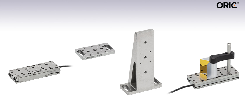
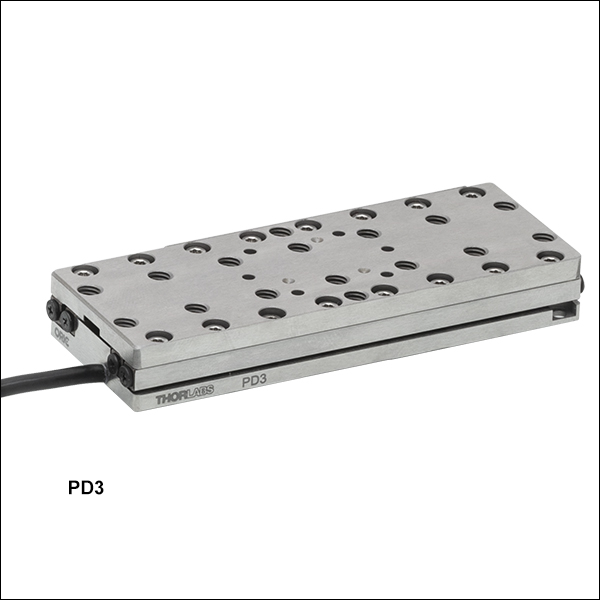
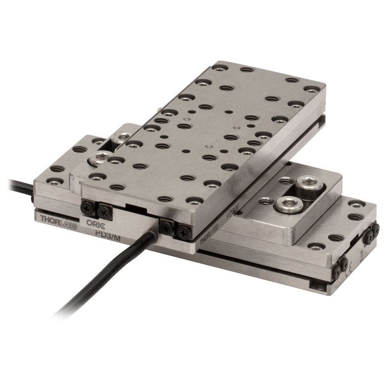
PD3
Piezo Inertia Stage
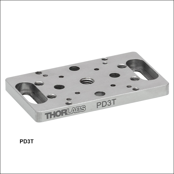
PD3T(/M)
Adapter Plate
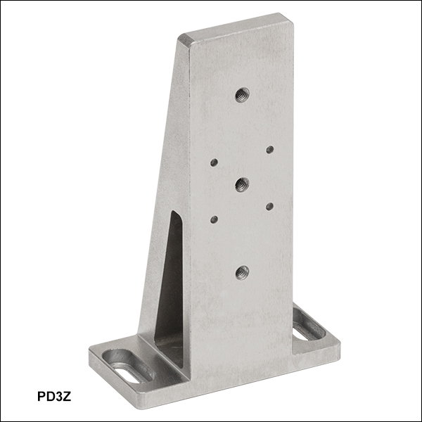
PD3Z
Right-Angle
Bracket
Application Idea
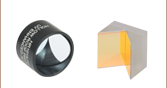
PD3 Stage with Hollow Roof Prism
and PM4 Clamping Arm


Please Wait

| Quick Links |
|---|
| Linear Stage |
| Adapters |
| Controllers |
| ORIC® Piezo Inertia Stage Selection Guide |
|---|
| 4.5 mm Vertical Translation Stage |
| 5 mm Linear Translation Stages |
| 20 mm Linear Translation Stages |
| 50 mm Linear Translation Stage |
| Rotation Stages |
| Vacuum-Compatible Stages |
Click to Enlarge
Three PD3(/M) Stages can be mounted in an XYZ configuration using the PD3T(/M) and PD3Z(/M) adapters.
Features
- Compact Stainless Steel Stage with Piezo Inertia Drive
- Ideal for OEMs and Set-and-Hold Applications that Require Relative Positioning with High Resolution
- Top Plate Adapter Provides Alternative Mounting Hole Patterns
- Mounting Adapter Provide Flat Surface for Mounting the Stage
- Right-Angle Bracket Adapter Allows Vertical Mounting and XYZ Configurations
- Requires a Piezo Inertia Stage Controller (Sold Separately Below)
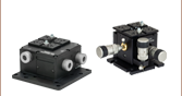
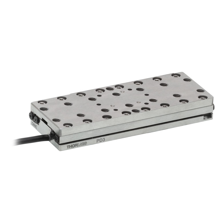
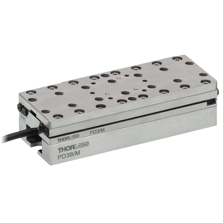
Thorlabs' PD3(/M) ORIC® Piezoelectric Inertia Drive Stage (U.S. Patent 11,606,045) provides fast and stable piezo-controlled linear motion in a compact package with no backlash. This stage provides open-loop operation and a horizontal load capacity of 3 kg. The piezo inertia drive is self-locking when the stage is at rest and no power is supplied to the piezo, making this stage ideal for set-and-hold applications that require nanometer resolution and long-term alignment stability.
Load Mounting Options
The load can be secured to the stage's moving platform using 8-32 (M4 x 0.7) threaded holes. Alternatively, the PD3T(/M) adapter plate (sold separately below) provides alternate mounting hole patterns for the top plate of the stage. The load can be aligned using an array of Ø2 mm, 1.5 mm deep dowel pin holes in the moving platform or the adapter plate; see the drawings below for details. Thorlabs also offers replacement dowel pins in packs of 20 below. Ensure that the maximum insertion depth of these holes is not exceeded or else the stage may be damaged. For more information, please refer to the Specs tab or the support documents accessible through the red Support Docs icons (![]() ) below.
) below.
Stage Mounting Options
The mounting counterbores are accessible when the moving plate is translated to the ends of the travel range. There are two mounting options: two 2-56 (M2 x 0.4) screws on the corners with 0.35 N·m recommended torque or two 8-32 (M4 x 0.7) screws along the center line with 0.55 N·m recommended torque. We offer the TD75 torque driver for tightening to a specific torque value.
The stage should be mounted on an even surface with a recommended flatness of ≤5 μm. If the stage is mounted on a surface with >5 µm flatness (as with most breadboards and optical tables), the mounting torque may need to be decreased for the velocity variation and pitch/yaw of the stage to meet specifications. If needed, the PD3B(/M) and PD1B3(/M) mounting adapters provide a mounting surface with precise flatness to avoid warping the stage when mounting it to a table surface.
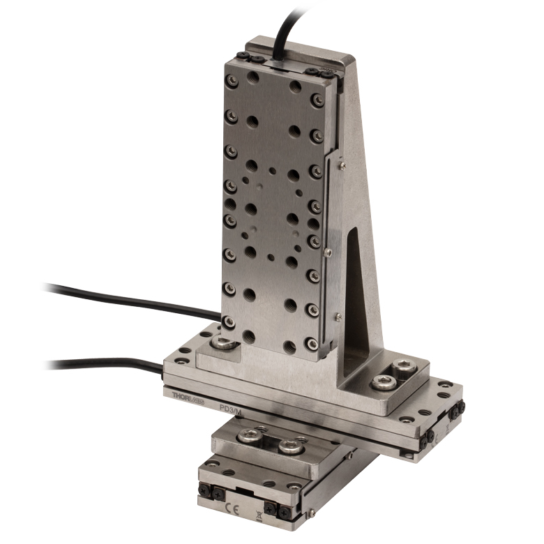
Two linear stages can be stacked on top of each other in an XY configuration for applications that require additional movement. The PD3Z(/M) right-angle bracket adapter allows one single-axis stage to be mounted vertically on top of another stage for an XZ or XYZ configuration, as shown in the photo to the right. Note that when the stage is mounted vertically, the load capacity is greatly reduced.
Compatibility with Other ORIC Stages
Other ORIC stages can be mounted onto the PD3(/M) 50 mm stage. PD1 Series 20 mm Stages can be mounted directly to the PD3(/M) stage's top plate, and PD2 Series 5 mm Stages can be attached using a PD2U(/M) Adapter Plate. For applications that require translation and rotation, an ORIC rotation stage can be mounted on top of a PD3(/M) stage using ER05-P4 cage rods and the PD3T(/M) adapter plate.
Required Controller
A PDXC Piezo Inertia Stage Controller, PDXC2 Compact Piezo Inertia Stage Controller, KIM001 Single-Channel K-Cube™ Piezo Inertia Motor Controller, or KIM101 Four-Channel K-Cube Piezo Inertia Motor Controller, available below, is required to operate this stage; the piezo inertia drive cannot be driven using a standard piezo controller. To drive the PD3(/M) stage, the PDXC controller requires firmware revision 1.27 or higher (indicated when the controller is powered on). The KIM001 or KIM101 controller must be from 2019 or newer (noted on the S/N label) with a firmware revision of 010003 or higher (indicated when the controller is powered on). Older firmware will not function properly and may cause failure of the stage and/or the controller. Since the PDXC and PDXC2 controller operates at higher frequencies but outputs a lower maximum voltage than the K-Cube controllers, it is capable of driving the PD3(/M) stage at a higher speed with a smaller step size and lower driving force. See the Specs tab for stage performance when used with each type of controller.
Click to Enlarge
Simplified Illustration Showing the Operation of the Piezo Inertia Drive
The "stick-slip" cycle consists of a slow piezo expansion and a fast piezo contraction.
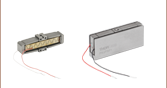
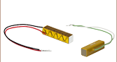
Piezoelectric Inertia "Stick-Slip" Motor
The piezo inertia motor consists of three main parts: a flexure-coupled piezo actuator, a friction element, and a slider (the moving platform). During the "stick" part of a cycle, the piezo slowly expands under the ramp voltage, pushing the friction element and the slider forward in unison. During the "slip" part, the drive voltage drops rapidly and the piezo element returns to its starting length, with the friction element "slipping" backward. The slider does not move due to its inertia and the low coefficient of kinetic friction between the friction element and the bottom surface of the slider. The graph to the right shows the piezo drive voltage during one "stick-slip" cycle.
Repeating this cycle produces continuous forward travel of the slider. For travel in the reverse direction, the opposite drive voltage pattern is required, resulting in rapid piezo expansion and slower piezo contraction, or "slip-stick". During operation, the stage makes a high pitch noise and may generate some heat. This is normal behavior in the performance of the device and does not indicate a fault condition.
Due to a number of factors that include the application conditions, piezo hysteresis, component variance, and the axial load, the achieved step size will vary and is not repeatable. To help overcome this variance, an external feedback system will be necessary.
| PD3(/M) Stage Specificationsa | ||
|---|---|---|
| Driving Controller | PDXC or PDXC2 Benchtop Controller | KIM001 or KIM101 K-Cube Controllers |
| Travel | 50 mm (2") | |
| Step Size | Minimum: 0.1 µmb Maximum: <1 µmc Adjustability: From 0.1 μm to 1 μmc |
Minimum: 1.0 µmb Maximum: <3 µmc Adjustability: ≤30%c |
| Maximum Step Frequency | 20 kHz | 2 kHz |
| Speed (Continuous Stepping)d,e | 10 mm/s Typical Max | 3 mm/s Typical Max |
| Average Speed Variation Over Travel Rangee,f |
±10% | |
| Horizontal Load Capacity | 3 kg (6.61 lbs) | |
| Vertical Load Capacityg | 100 g (3.5 oz) | 120 g (4.2 oz) |
| Clamping / Holding Force | 6 N | |
| Pitch / Yaw Over Travel Range | 200 µrad | |
| XY Stacked Orthogonality | <5 mrad | |
| Motor Type | Piezoelectric Inertia Drive | |
| Lifetimeh | >10 Billion Steps | |
| Piezo Specifications | ||
| Max Operating Voltage | 50 V (Item # PDXC) or 56 V (Item # PDXC2) | 125 V |
| Capacitance | 170 nF | |
| Physical Specifications | ||
| Operating Temperature | 10 to 40 °C (50 to 104 °F) | |
| Connector Type | D-Sub Female | SMC Female (PD2AD Adapter Required, Sold Separately) |
| Cable Length | Integrated Cable: 1 m (3.3 ft), PDXCE Cable (Optional, Not Included): 3 m (9.8 ft)i |
Integrated Cable: 1 m (3.3 ft) & PD2AD Adapter (Required, Not Included): 1 m (3.3 ft)j |
| Top Plate Mounting Options |
Sixteen 8-32 (M4 x 0.7) Threaded Holes, 3.2 mm Deep Six Ø2 mm Dowel Pin Holes, 1.5 mm Deep PD3T(/M) Adapter |
|
| Dimensions | 83.5 mm x 32.0 mm x 11.5 mm (3.29" x 1.26" x 0.45") |
|
| Weight (Including Cable) | 210 g (7.41 oz) | |
| Required Controller (Sold Separately Below)k,l |
PDXC, PDXC2, KIM001, or KIM101 | |
PD3(/M) Stage
Female 15-Pin D-Sub
PD2AD(/M) Adapter Cable
Male 15-Pin D-Sub
SMC Female

0 to 125 V
| Pin(s) | Voltage | Name | Description |
|---|---|---|---|
| 3 | 0 V | GND | Digital Ground |
| 12 | 0 V | PGND | Power Ground |
| 13 | 125 V Max | SigOut1 | Piezo Output 1 |
| 14 | 5 V TTL | EEPROM | 1-Wire EEPROM |
| 1, 2, 4-11, 15 | - | - | Reserved |
| D-Sub Pin(s) | SMC Connector | Voltage | Name | Description |
|---|---|---|---|---|
| 12 | Outer Shield | 0 V | PGND | Power Ground |
| 13 | Core Wire | 125 V Max | SigOut1 | Piezo Output 1 |
| 1-11, 14, 15 | - | - | - | Reserved |
Software
PDXC Version 2.0.0
The PDXC Software Package, which includes a GUI, drivers, and LabVIEW™/C++/Python SDK for third-party development.
Thorlabs offers the PDXC software package to interface with the PDXC Piezo Stage Controller. This controller is designed to drive the following piezo inertia stages:
- PDXZ1(/M) 4.5 mm Vertical Stage with Optical Encoder
- PD2(/M) 5 mm Linear Stage
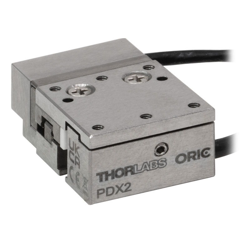
- PDX2(/M) 5 mm Linear Stage with Optical Encoder
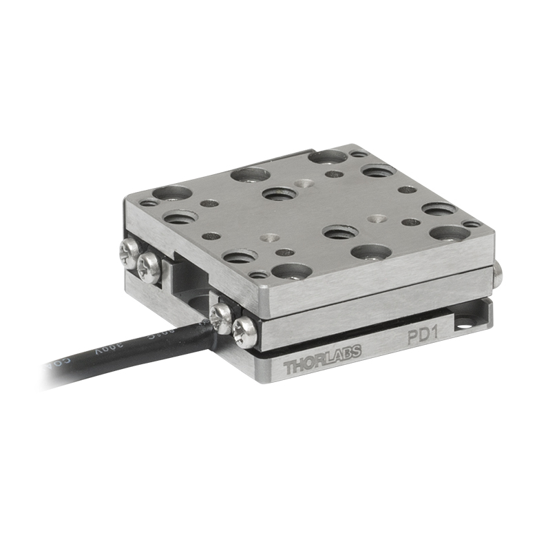
- PD1(/M) 20 mm Linear Stage
- PD1V(/M) Vacuum-Compatible 20 mm Linear Stage
- PD1D(/M) 20 mm Monolithic XY Stage
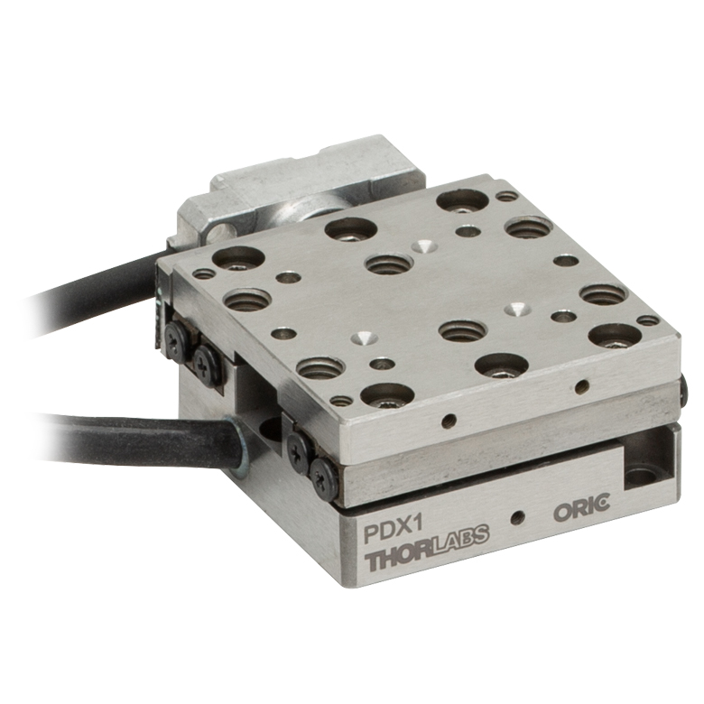
- PDX1(/M) 20 mm Linear Stage with Optical Encoder
- PD3(/M) 50 mm Linear Stage
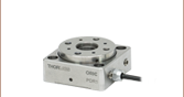
- PDR1C(/M) Rotation Stage
- PDXR1(/M) Rotation Stage with Optical Encoder
The software package allows two methods of usage: graphical user interface (GUI) utilities for direct interaction with and control of the controllers 'out of the box', and a set of programming interfaces for third-party development of custom-integrated positioning and alignment solutions to be easily programmed in the development language of choice (LabVIEW™/C++/Python SDK).
Note: This software is compatible with the PDXC2, KIM001, and KIM101 controllers; it cannot be used to operate the PDXC controller. The PDXC2 controller is only compatible with the Kinesis® software.
Software
Kinesis Version 1.14.50
The Kinesis Software Package, which includes a GUI for control of Thorlabs' Kinesis system controllers.
Also Available:
- Communications Protocol

Kinesis GUI Screen
Thorlabs offers the Kinesis® software package to drive our wide range of motion controllers. The software can be used to control devices in the Kinesis family, which covers a wide variety of motion controllers ranging from small, low-powered, single-channel drivers (such as the K-Cubes™) to high-power, multi-channel benchtop units and modular 19" rack nanopositioning systems (the MMR60x Rack System).
The Kinesis Software features .NET controls which can be used by 3rd party developers working in the latest C#, Visual Basic, LabVIEW™, or any .NET compatible languages to create custom applications. Low-level DLL libraries are included for applications not expected to use the .NET framework and APIs are included with each install. A Central Sequence Manager supports integration and synchronization of all Thorlabs motion control hardware.
By providing this common software platform, Thorlabs has ensured that users can mix and match any of our motion control devices in a single application, while only having to learn a single set of software tools. In this way, it is perfectly feasible to combine any of the controllers from single-axis to multi-axis systems and control all from a single, PC-based unified software interface.
The software package allows two methods of usage: graphical user interface (GUI) utilities for direct interaction with and control of the controllers 'out of the box', and a set of programming interfaces that allow custom-integrated positioning and alignment solutions to be easily programmed in the development language of choice.
Legacy Software
Select products are still capable of running the legacy APT™ software package. Information on software compatibility can be found in the product documentation ( ), and additional details about the APT software can be found here.
Thorlabs' Kinesis® software features new .NET controls which can be used by third-party developers working in the latest C#, Visual Basic, LabVIEW™, or any .NET compatible languages to create custom applications.
C#
This programming language is designed to allow multiple programming paradigms, or languages, to be used, thus allowing for complex problems to be solved in an easy or efficient manner. It encompasses typing, imperative, declarative, functional, generic, object-oriented, and component-oriented programming. By providing functionality with this common software platform, Thorlabs has ensured that users can easily mix and match any of the Kinesis controllers in a single application, while only having to learn a single set of software tools. In this way, it is perfectly feasible to combine any of the controllers from the low-powered, single-axis to the high-powered, multi-axis systems and control all from a single, PC-based unified software interface.
The Kinesis System Software allows two methods of usage: graphical user interface (GUI) utilities for direct interaction and control of the controllers 'out of the box', and a set of programming interfaces that allow custom-integrated positioning and alignment solutions to be easily programmed in the development language of choice.
For a collection of example projects that can be compiled and run to demonstrate the different ways in which developers can build on the Kinesis motion control libraries, click on the links below. Please note that a separate integrated development environment (IDE) (e.g., Microsoft Visual Studio) will be required to execute the Quick Start examples. The C# example projects can be executed using the included .NET controls in the Kinesis software package (see the Kinesis Software tab for details).
 |
Click Here for the Kinesis with C# Quick Start Guide Click Here for C# Example Projects Click Here for Quick Start Device Control Examples |
|
LabVIEW
LabVIEW can be used to communicate with any Kinesis- or APT-based controller via .NET controls. In LabVIEW, you build a user interface, known as a front panel, with a set of tools and objects and then add code using graphical representations of functions to control the front panel objects. The LabVIEW tutorial, provided below, provides some information on using the .NET controls to create control GUIs for Kinesis- and APT-driven devices within LabVIEW. It includes an overview with basic information about using controllers in LabVIEW and explains the setup procedure that needs to be completed before using a LabVIEW GUI to operate a device.
 |
Click Here to View the LabVIEW Guide Click Here to View the Kinesis with LabVIEW Overview Page |
|
Achieving the Specified Performance
In this application note, we will discuss how to achieve the specified velocity and step size for the open-loop PD1(/M), PD1D(/M), and PDR1(/M) ORIC® Stages when driving them with KIM001 or KIM101 K-Cube™ Controllers; examples using the Kinesis® software and the K-Cube's front panel controls are discussed below. There are limitations when using an open-loop system, and we have created this application note to help minimize velocity and step size variation. We recommend using this application note upon initial setup, and/or if you are having issues with velocity and step size variation. For further details on how to change settings, please refer to the manuals of the individual stage and controller.
Click to Enlarge
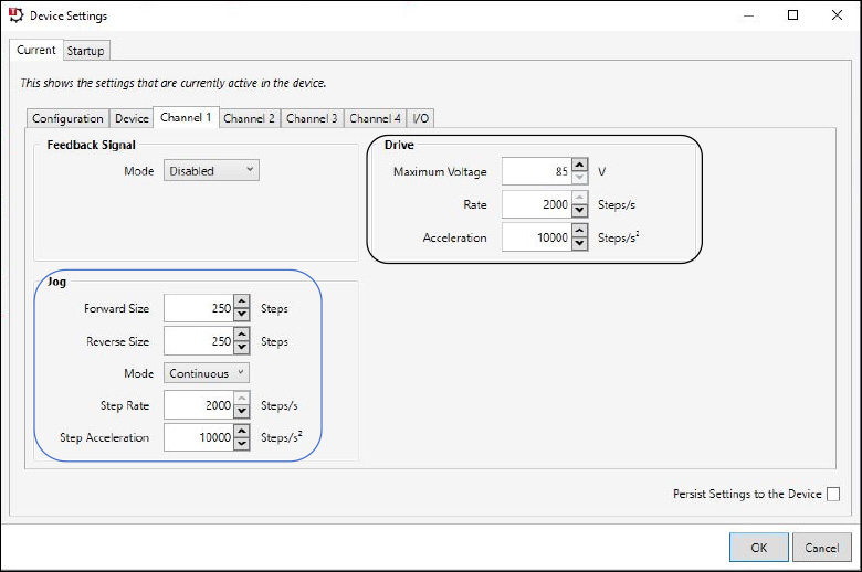
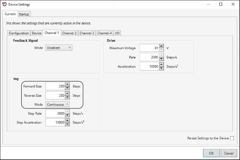
Figure 2: These are the recommended channel settings for the PD(R) stage type. They can be changed in Device Settings -> Current Device Settings-> Channel 1.
Click to Enlarge
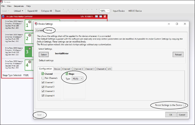
Figure 1: When controlling an ORIC Stage, the stage type needs to be set to PD(R). This can be found in the Kinesis Software Device Settings -> Startup.
Click to Enlarge
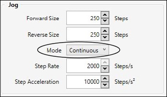
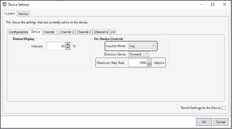
Figure 4: Depicted in the circle is the jog mode, which should be set to continuous. This can be changed in Device Settings -> Current ->

Figure 3: Circled in black are the jog buttons which can be found in the device GUI.
Kinesis© Software Control with a K-Cube Controller
The Kinesis software defaults the stage type to PIA, which is not applicable to ORIC stages; to change this, we need to change the startup settings. The startup settings can be found by first accessing the device settings in the device GUI panel and then clicking the Startup tab. Under the Configuration tab, change the stage type to PD(R), check the "Persist Settings to the Device" box on the bottom right, and click the "Save" button in the lower left corner. These selections are shown circled in Figure 1. By using these settings, the Kinesis software will use the PD(R) stage type. The other device and channel settings can also be changed in the startup settings.
With the PD(R) stage type, we recommend certain channel settings to achieve the specified speed, speed variation, and force. These settings can be changed in the "Channel 1" tab of the device settings and are depicted in Figure 2. We will be focusing on the settings in the “Drive” box, circled in black, and the "Jog" box, circled in blue.
For the "Drive" box, we recommend setting the "Maximum Voltage" to 85 V, the "Rate" at 2000 steps/s, and "Acceleration" to 10000 Steps/s2. For the settings in the "Jog" box, we recommend setting the "Forward Size" to 250 Steps, the "Reverse Size" to 250 Steps, the "Mode" to "Continuous", the "Step Rate" to 2000 Steps/s, and the "Step Acceleration" to 10000 Steps/s2. To achieve the specified results, it is important to make sure the stage is mounted properly to an even surface, to our recommended mounting plate, or to a compatible adapter plate.
A continuous jog at a step rate higher than 1000 steps/s can only be achieved by using the jog buttons in the device GUI, shown circled in Figure 3. Continuous jog movement is limited to within 1000 step/s when using the joystick on the KIM101 K-Cube Controller or wheel on the KIM001 K-Cube Controller. Single movement or movement by counts is not limited to 1000 step/s when using the joystick or wheel.
Please note that if you change the jog mode in Kinesis to "Continuous" or "Single" this will only influence the jog buttons in the Kinesis GUI, shown circled in Figure 3. This will not change the joystick mode on the KIM001 or KIM101 controller front panel. The jog mode can be found in Kinesis under Device settings -> Channel 1 -> "Jog" box -> "Mode", also shown in Figure 4. More information on this can be found in the Front Panel Control section, located below.
Click to Enlarge
Figure 6: Kinesis software showing the "Device" tab under Device Settings in the Device GUI. The "Maximum Step Rate" setting is circled in blue. To use the joystick with continuous jogging mode this setting must be less than 1000 steps/s. The Kinesis joystick modes can be selected via the dropdown menu circled in black.
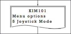
Figure 5: Drawing of the front panel of the KIM101 K-Cube Controller showing option 5, Joystick Mode.
Click to Enlarge
Figure 8: Kinesis software showing where the step size can be changed using the "Forward Size" and "Reverse Size" settings. The "Mode" setting, also shown, only affects the controls of the jog buttons in the GUI and does not affect the joystick mode.

Click to Enlarge
Figure 7: The drive rate can be changed in the Kinesis software under Device Settings -> Current -> Channel 1. This is equivalent to Front Panel Control option 3, "Set Velocity".
KIMx01 Front Panel Control and Related Settings in Kinesis
There are 10 options on the front panel control menu. These can be accessed using the two buttons and joystick on the KIM101 K-Cube Controller or the button and wheel on the KIM001 K-Cube Controller.
Option 5, Joystick Mode, shown in Figure 5, has 3 modes: "Jog to Count", "Jogging in Steps", and "Velocity Control". The Joystick mode in the Kinesis software is related to option 5, Joystick Mode, on the front panel. The three options for the Joystick Mode in the Kinesis software are "Step Rate", "Jog", and "Goto Position". This setting is circled in black in Figure 6.
"Jog to Count" mode will move the stage to the target count, which is defaulted at 0, under the velocity that is set by option 3, "Set Velocity" on the front panel. The setting for option 3 is the velocity at which the stage will move for option 5’s “Jog to Count” mode and for option 1, "Goto Pos Count". There is an equivalent setting in Kinesis which can be found in Device Settings -> Channel 1 -> "Drive" box -> "Rate". This is shown in Figure 7.
In "Jogging in Steps" mode, option 3, "Set Velocity" does not change the stage's velocity. The velocity in this mode must be changed in the Kinesis software. This can be changed in Device settings -> Channel 1 -> "Jog" box -> "Step Rate". Instead of changing the step rate to increase the stage speed, the step size can be changed to increase the stage speed. The step size can be changed on the front panel of a KIM001 or KIM101 device through option 4, "Jog Step Size". This can also be achieved in Kinesis through Device settings -> "Channel 1" -> "Jog" box-> "Forward Size" and "Reverse Size", shown in Figure 8.
In option 5 "Velocity Control" mode, the joystick can be used to achieve continuous jogging, but only if the velocity is less than 1000 step/s. This velocity cannot be changed by option 3 on the front panel. The velocity can only be changed in the Kinesis software under the Device settings -> Device -> "Maximum Step Rate", shown in Figure 6. A value of 10000 may appear initially, but this value is not accepted by the software and must be revised to a number between 1 and 1000.
In Kinesis, the joystick mode "Step Rate", is related to the "Velocity Control" mode on the front panel and can use the setting of "Maximum Step Rate". The "Direction Sense" can be used to switch the travel direction when using the joystick or wheel.
| Posted Comments: | |
| No Comments Posted |
Motorized Linear Translation Stages
Thorlabs' motorized linear translation stages are offered in a range of maximum travel distances, from a stage with 20 µm of piezo translation to our 600 mm direct drive stage. Many of these stages can be assembled in multi-axis configurations, providing XY or XYZ translation. For fiber coupling applications, please see our multi-axis stages, which offer finer adjustment than our standard motorized translation stages. In addition to motorized linear translation stages, we offer motorized rotation stages and goniometers. We also offer manual translation stages.
Piezo Stages
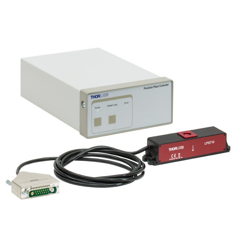
These stages incorporate piezoelectric elements in a variety of drive mechanisms. ORIC® stages incorporate piezo inertia drives that use "stick-slip" friction properties to obtain extended travel ranges. Our Nanoflex™ translation stages use standard piezo chips along with manual actuators. Elliptec® stages use resonant piezo motors to push and pull the moving platform through resonant elliptical motion. Our LPS710E z-axis stage features a mechanically amplified piezo design and includes a matched controller.
| Piezoelectric Stages | ||||
|---|---|---|---|---|
| Product Family | ORIC® PDXZ1 Closed-Loop 4.5 mm Vertical Stage |
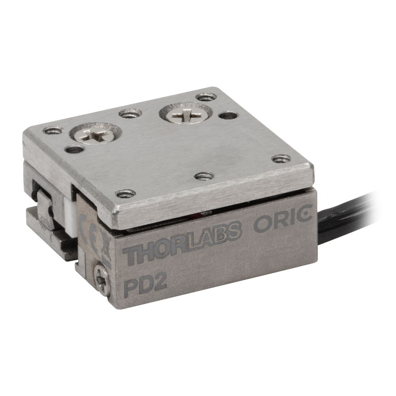
ORIC® PD2 Open-Loop 5 mm Stage |
ORIC® PDX2 Closed-Loop 5 mm Stage |
|
| Click Photo to Enlarge |
 |
 |
 |
|
| Travel | 4.5 mm | 5 mm | ||
| Speed | 1 mm/s (Typ.)a | 10 mm/s (Typ. Max)b | 8 mm/s (Typ.)c | |
| Drive Type | Piezoelectric Inertia Drive | |||
| Possible Axis Configurations | Z | X, XY, XYZ | ||
| Mounting Surface Size |
45.0 mm x 42.0 mm | 13 mm x 13 mm | ||
| Additional Details | ||||
| Piezoelectric Stages | |||||
|---|---|---|---|---|---|
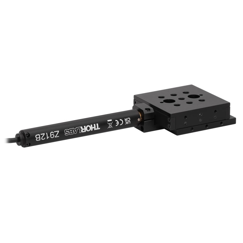
| Product Family | ORIC® PD1 Open-Loop 20 mm Stage |
ORIC® PD1D Open-Loop 20 mm Monolithic XY Stage |
ORIC® PDX1 Closed-Loop 20 mm Stage |
ORIC® PD3 Open-Loop 50 mm Stage |
|
| Click Photo to Enlarge |
 |
 |
 |
 |
|
| Travel | 20 mm | 50 mm | |||
| Speed | 3 mm/s (Typ. Max)a | 20 mm/s (Typ. Max)b | 10 mm/sc | ||
| Drive Type | Piezoelectric Inertia Drive | ||||
| Possible Axis Configurations | X, XY, XYZ | XY, XYZ | X, XY, XYZ | X, XY, XYZ | |
| Mounting Surface Size |
30 mm x 30 mm | 80 mm x 30 mm | |||
| Additional Details | |||||
| Piezoelectric Stages | ||||||
|---|---|---|---|---|---|---|
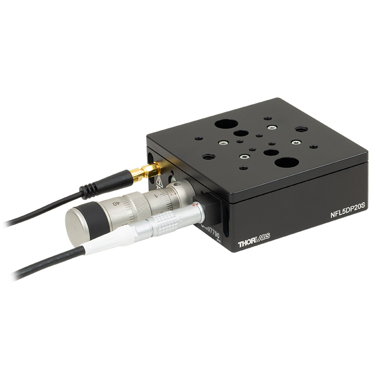
| Product Family | Nanoflex™ 20 µm Stage with 5 mm Actuator |
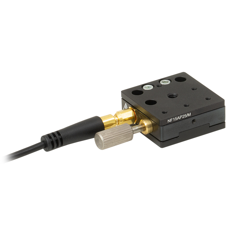
Nanoflex™ 25 µm Stage with 1.5 mm Actuator |
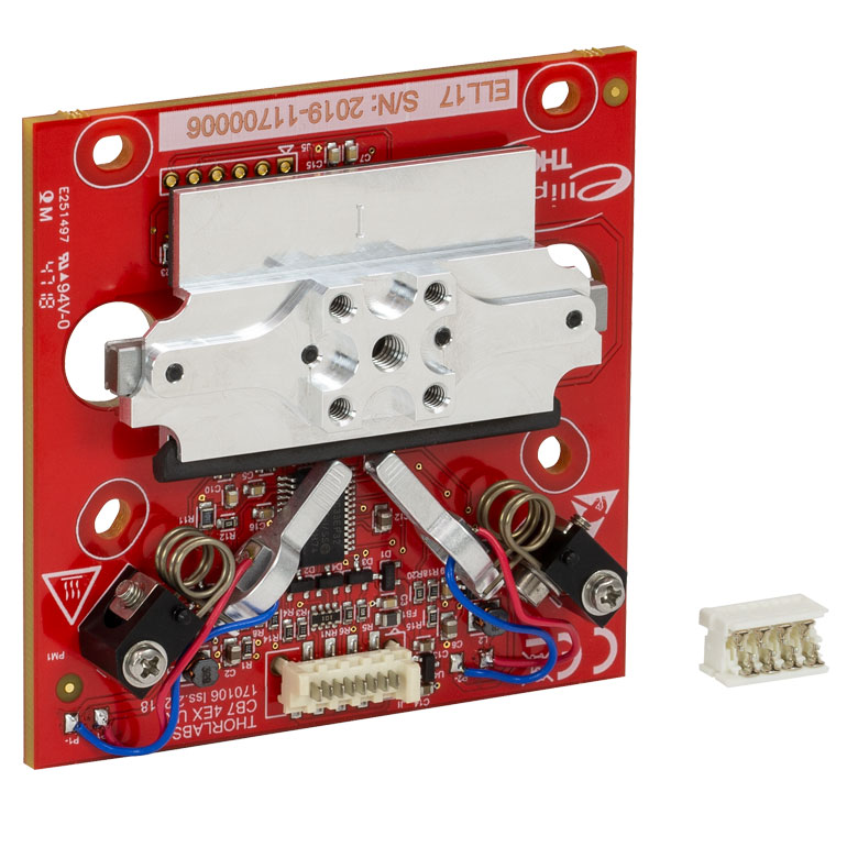
Elliptec® 28 mm Stage | Elliptec® 60 mm Stage | LPS710E 1.1 mm Vertical Stage | |
| Click Photo to Enlarge |
 |
 |
 |
 |
 |
|
| Travel | 20 µm + 5 mm Manual | 25 µm + 1.5 mm Manual | 28 mm | 60.0 mm | 1.1 mm | |
| Maximum Velocity | - | 180 mm/s | 90 mm/s | - | ||
| Drive Type | Piezo with Manual Actuator | Resonant Piezoelectric Motor | Amplified Piezo | |||
| Possible Axis Configurations | X, XY, XYZ | X | Z | |||
| Mounting Surface Size | 75 mm x 75 mm | 30 mm x 30 mm | 15 mm x 15 mm | 21 mm x 21 mm | ||
| Additional Details | ||||||
Stepper Motor Stages
These translation stages feature removable or integrated stepper motors and long travel ranges up to 300 mm. Many of these stages either have integrated multi-axis capability (PLSXY) or can be assembled into multi-axis configurations (PLSX, LNR Series, NRT Series, and LTS Series stages). The MLJ150 stage also offers high load capacity vertical translation.
| Stepper Motor Stages | |||||
|---|---|---|---|---|---|
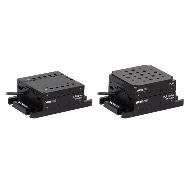
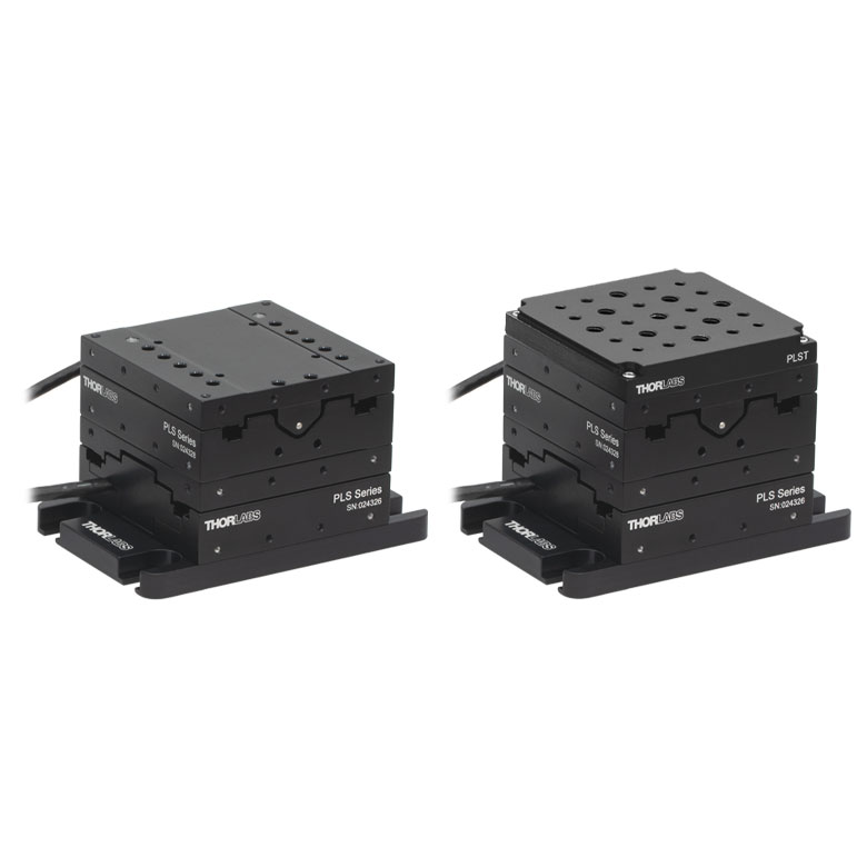
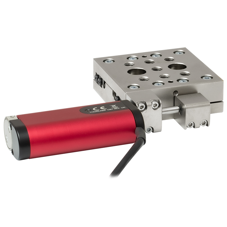
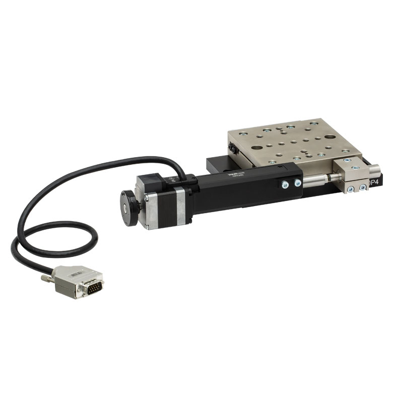
| Product Family | PLSX with and without PLST(/M) Top Plate 1" Stage |
PLSXY with and without PLST(/M) Top Plate 1" Stage |
LNR Series 25 mm Stage |
LNR Series 50 mm Stage |
|
| Click Photo to Enlarge |
 |
 |
 |
 |
|
| Travel | 1" | 25 mm | 50 mm | ||
| Maximum Velocity | 7.0 mm/s | 2.0 mm/s | 50 mm/s | ||
| Possible Axis Configurations |
X, XY | X, XY, XYZ | X, XY, XYZ | ||
| Mounting Surface Size |
3" x 3" | 60 mm x 60 mm | 100 mm x 100 mm | ||
| Additional Details | |||||
| Stepper Motor Stages | ||||||
|---|---|---|---|---|---|---|
| Product Family | NRT Series 100 mm Stage |
NRT Series 150 mm Stage |
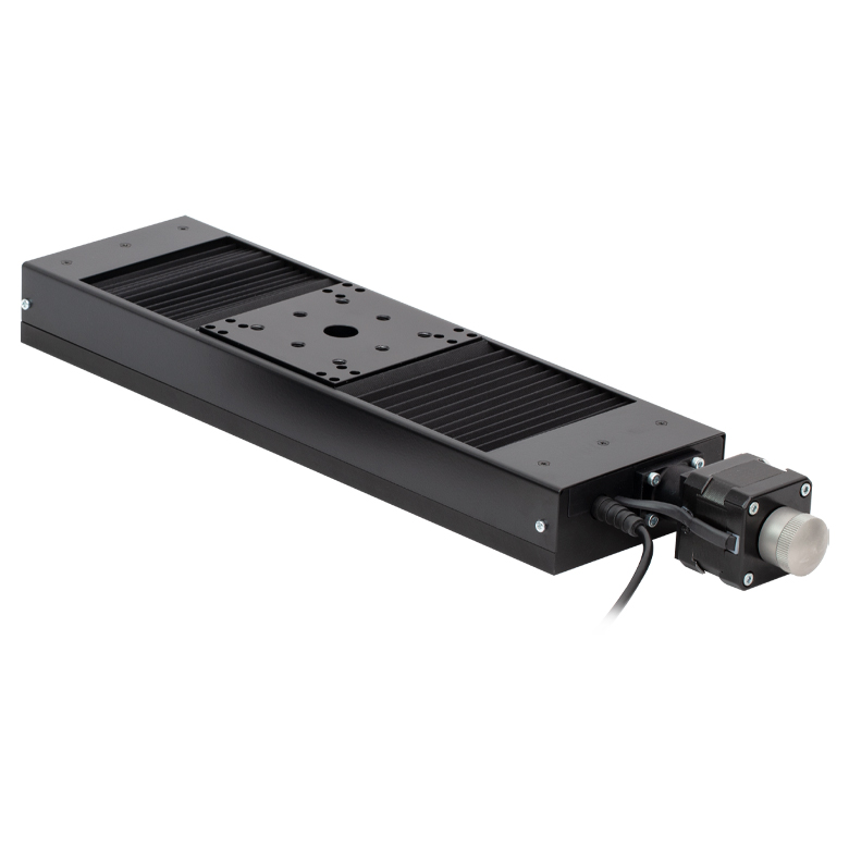
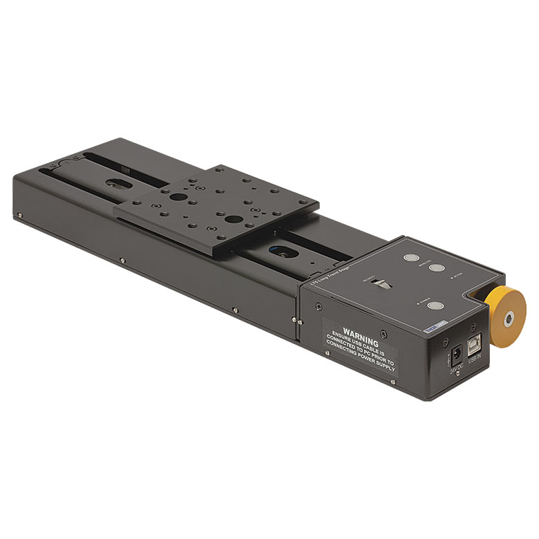
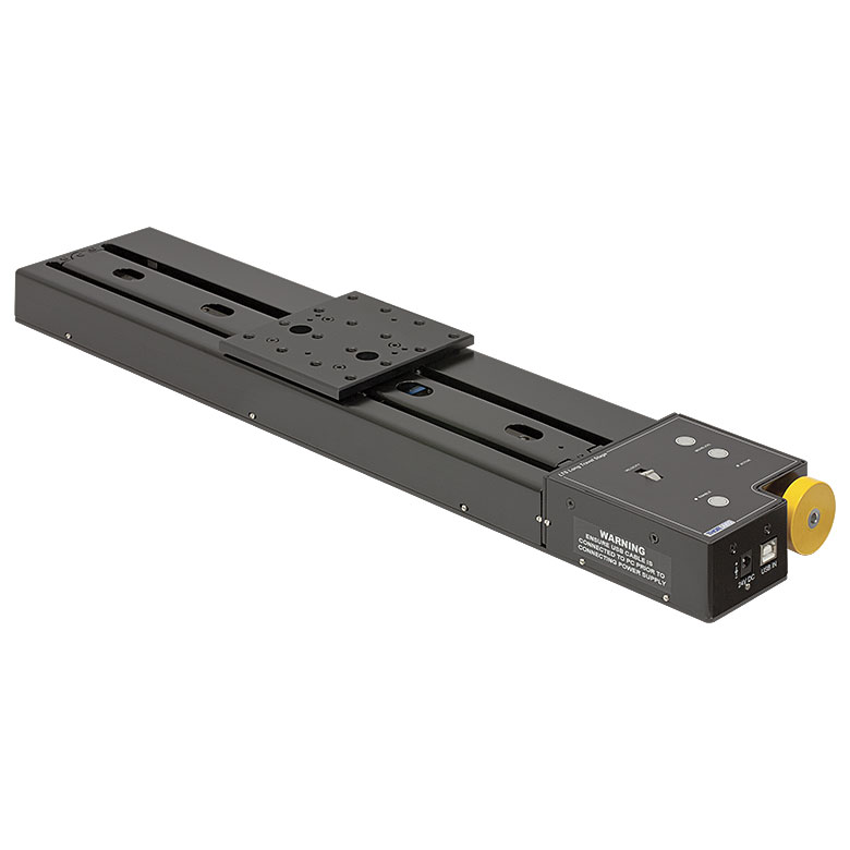
LTS Series 150 mm Stage |
LTS Series 300 mm Stage |
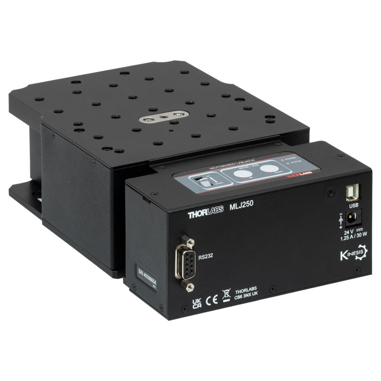
MLJ250 50 mm Vertical Stage |
|
| Click Photo to Enlarge |
 |
 |
 |
 |
 |
|
| Travel | 100 mm | 150 mm | 150 mm | 300 mm | 50 mm | |
| Maximum Velocity | 30 mm/s | 50 mm/s | 3.0 mm/s | |||
| Possible Axis Configurations |
X, XY, XYZ | X, XY, XYZ | Z | |||
| Mounting Surface Size |
84 mm x 84 mm | 100 mm x 90 mm | 148 mm x 131 mm | |||
| Additional Details | ||||||
DC Servo Motor Stages
Thorlabs offers linear translation stages with removable or integrated DC servo motors. These stages feature low profiles and many can be assembled in multi-axis configurations.
| DC Servo Motor Stages | ||||
|---|---|---|---|---|
| Product Family | MT Series 12 mm Stages |
PT Series 25 mm Stages |
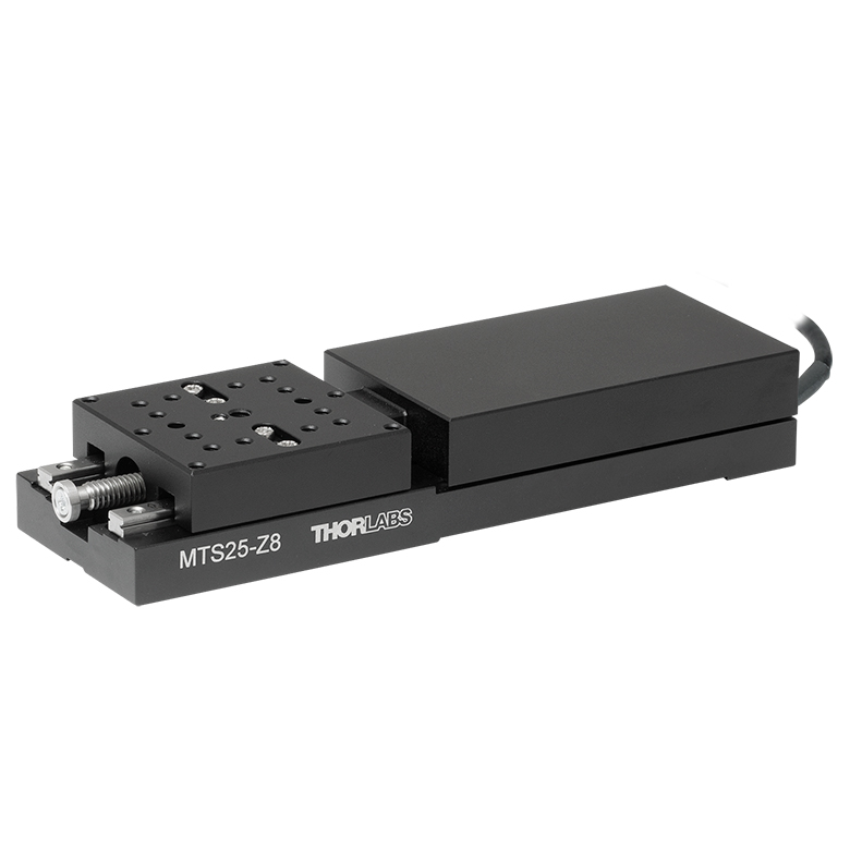
MTS Series 25 mm Stage |
MTS Series 50 mm Stage |
| Click Photo to Enlarge |
 |
 |
 |
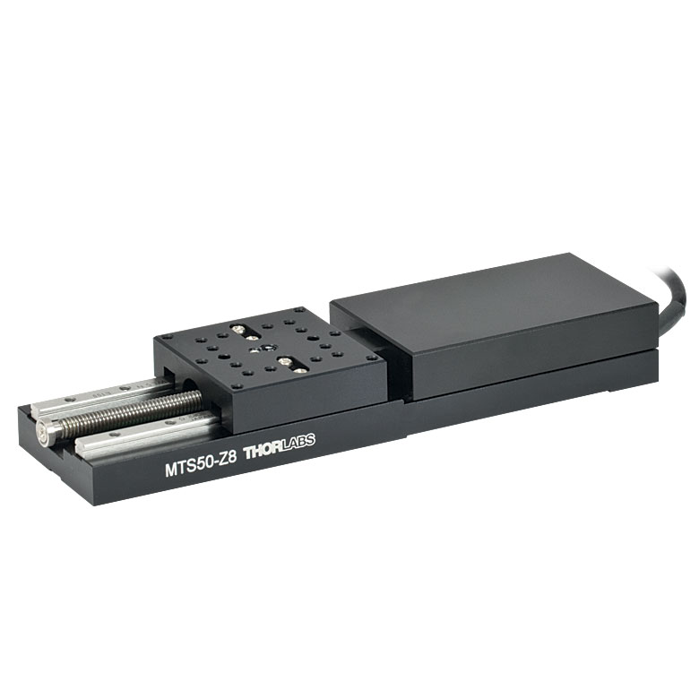 |
| Travel | 12 mm | 25 mm | 25 mm | 50 mm |
| Maximum Velocity | 2.6 mm/s | 2.4 mm/s | ||
| Possible Axis Configurations | X, XY, XYZ | X, XY, XYZ | ||
| Mounting Surface Size |
61 mm x 61 mm | 101.6 mm x 76.2 mm | 43 mm x 43 mm | |
| Additional Details | ||||
| DC Servo Motor Stages | ||||
|---|---|---|---|---|
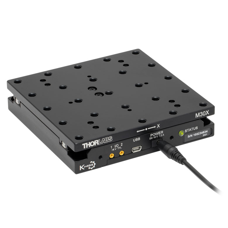
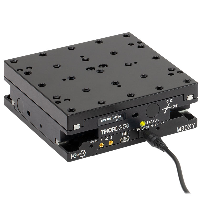
| Product Family | M30 Series 30 mm Stage |
M30 Series 30 mm Monolithic XY Stage |
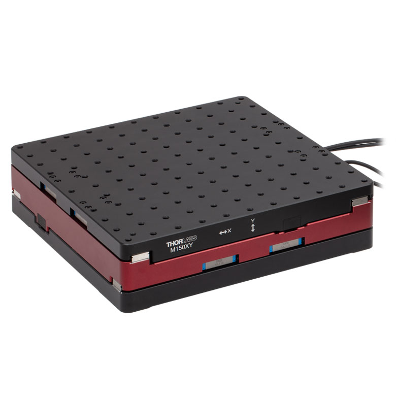
M150 Series 150 mm XY Stage |
KVS30 30 mm Vertical Stage |
| Click Photo to Enlarge |
 |
 |
 |
 |
| Travel | 30 mm | 150 mm | 30 mm | |
| Maximum Velocity | 2.4 mm/s | X-Axis: 170 mm/s Y-Axis: 230 mm/s |
8.0 mm/s | |
| Possible Axis Configurations | X, Z | XY, XZ | XY | Z |
| Mounting Surface Size |
115 mm x 115 mm | 272.4 mm x 272.4 mm | 116.2 mm x 116.2 mm | |
| Additional Details | ||||
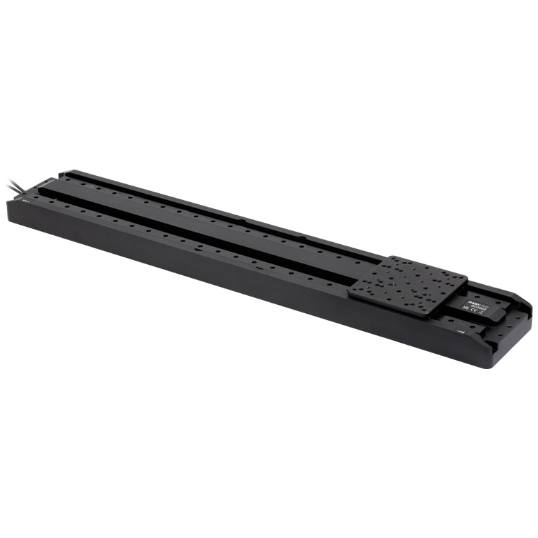
Direct Drive Stages
These low-profile stages feature integrated brushless DC servo motors for high speed translation with zero backlash. When no power is applied, the platforms of these stages have very little inertia and are virtually free running. Hence these stages may not be suitable for applications where the stage's platform needs to remain in a set position when the power is off. We do not recommend mounting these stages vertically.
| Direct Drive Stages | |||||
|---|---|---|---|---|---|
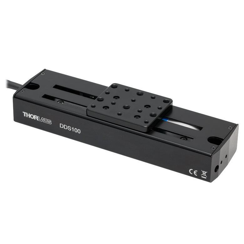
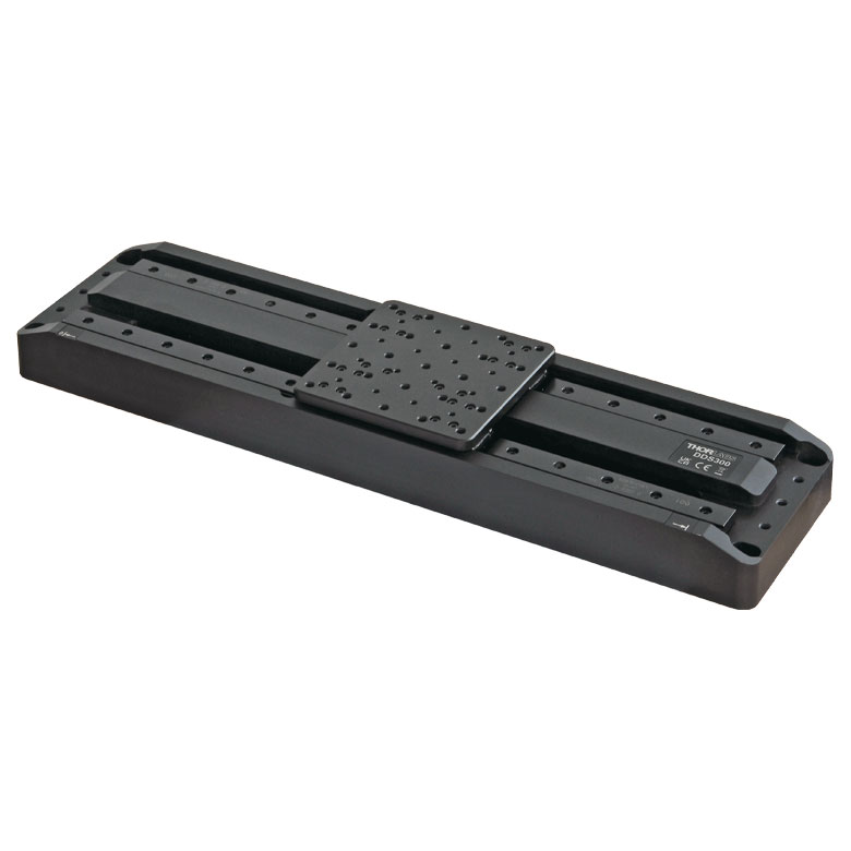
| Product Family | DDS Series 50 mm Stage |
DDS Series 100 mm Stage |
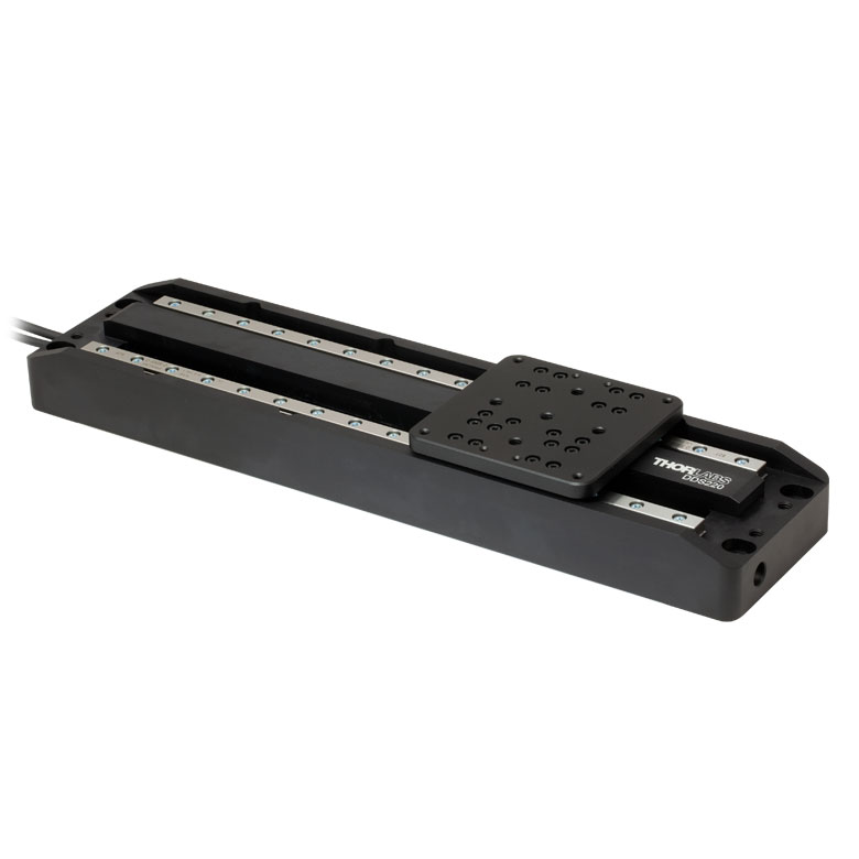
DDS Series 220 mm Stage |
DDS Series 300 mm Stage |
DDS Series 600 mm Stage |
| Click Photo to Enlarge |
 |
 |
 |
 |
 |
| Travel | 50 mm | 100 mm | 220 mm | 300 mm | 600 mm |
| Maximum Velocity | 500 mm/s | 300 mm/s | 400 mm/s | 400 mm/s | |
| Possible Axis Configurations | X, XY | X, XY | X | X | |
| Mounting Surface Size | 60 mm x 52 mm | 88 mm x 88 mm | 120 mm x 120 mm | ||
| Additional Details | |||||

 Zoom
Zoom
Click for Details
PD3(/M) Top Plate Schematic. Dimensions for the metric stage are given in parentheses.
Includes:
- Linear Stage with Integrated Cable,
D-Sub Female Connector - Two 2-56 (M2 x 0.4) Mounting Screws
- Two Ø2 mm Dowel Pins
- 9/64" (3.0 mm) Hex Key
- Open-Loop Operation
- Provides High-Resolution Positioning
- <5 mrad XY Stacked Orthogonality
- Speeds Up to 10 mm/s when Driven with PDXC or PDXC2 Controller
- Integrated 1 m (3.3 ft) Cable with D-Sub Female Connector
- Requires the PDXC, PDXC2, KIM001, or KIM101 Piezo Inertia Controller (Sold Separately Below)
The PD3(/M) ORIC® open-loop piezo inertia stage can support loads up to 3 kg, operates with no backlash, and can achieve speeds up to 10 mm/s when driven with a PDXC or PDXC2 controller. The piezo inertia drive is self-locking when the stage is at rest and no power is supplied to the piezo, making these actuators ideal for set-and-hold applications that require micrometer resolution and long-term alignment stability. See the Specs tab for detailed specifications.
The stage should be placed on a surface with flatness ≤5 µm. If needed, the PD3B(/M) or PD1B3(/M) mounting adapters (sold separately below) will provide a flat surface for the stage to reduce stage warping. Along with this, we also offer an alternative top plate adapter and a right-angle bracket adapter.
Each stage has an integrated 1.0 m cable with a 15-pin D-sub connector that can connect directly to a PDXC or PDXC2 controller. If additional cable length is needed, the 3 m long PDXCE Extension Cable (available separately below) can be used. Due to the capacitance of the cables, do not use cables longer than 4.5 m in total when connecting the stage to a PDXC controller.
Alternatively, the PD3(/M) stage can be connected to a KIM001 or KIM101 controller using the PD2AD adapter cable (1 m long; sold separately). Due to the capacitance of the cables, do not use cables longer than 2.5 m in total when connecting the stage to a KIMx01 controller.
Note: During operation, the stage makes a high-pitch noise and may generate some heat. This is normal behavior in the performance of the device and does not indicate a fault condition.

 Zoom
Zoom
Click for Details
PD3T(/M) Adapter Plate Schematic. Dimensions for the metric adapter plate are given in parentheses.
Click to Enlarge
Two PD3(/M) stages can be mounted in an XY configuration using the PD3T(/M) adapter.
- Provides Different Mounting Hole Pattern:
- 2-56 (M2 x 0.4) Mounting Holes
- 4-40 Mounting Holes for 30 mm Cage System or ORIC Rotation Stage
- 8-32 (M4 x 0.7) Mounting Holes
- #8 (M4) Counterbores for Second PD3(/M) Stage in XY Configuration (See Photo to the RIght)
- 1/4"-20 (M6 x 1.0) Mounting Hole
- Required for XY and XYZ Stage Configurations
- Each Adapter Includes Two 2-56 (M2 x 0.4) Mounting Screws and Two Ø2 mm Dowel Pins
The PD3T(/M) adapter plate provides alternative mounting holes for the PD3(/M) stage and enables XY configurations using two PD3(/M) stages. The adapter is secured to the top of the stage using four 8-32 (M4 x 0.7) cap screws in the two counterbore slots along with dowel pins for alignment. The top of the PD3T(/M) adapter plate offers a variety of mounting features including four 4-40 mounting holes which are spaced for 30 mm cage systems and also provide compatibility with an ORIC rotation stage using ER05 cage rods. The #8 (M4) counterbores on the underside of the plate can be used to mount a second PD3(/M) stage for an XY configuration, as shown in the photo above.

 Zoom
Zoom
Click for Details
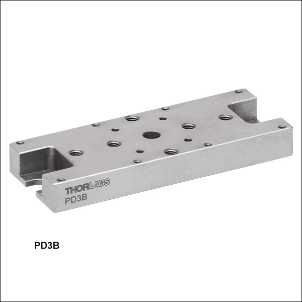
PD3B(/M) Mounting Adapter Schematic. Dimensions for the metric adapter are given in parentheses.
Click to Enlarge
PD3/M Stage Mounted to PD3B/M Adapter Base
- Provides Flat Surface for Mounting PD3(/M) Stage (See Photo to the Right)
- 1/4" (M6) Mounting Slots
- Reduces Stage Warping When Mounting to Table or Breadboard
- Variety of Mounting Features:
- 2-56 (M2 x 0.4) and 8-32 (M4 x 0.7) Corner Mounting Holes for PD3(/M) Stage
- 2-56 (M2 x 0.4) and 8-32 (M4 x 0.7) Mounting Holes Near Center for PD1 Series 20 mm Stages
- 1/4"-20 (M6 x 1.0) Mounting Hole on Underside for Ø1" and Ø1.5" Posts
The PD3B(/M) mounting adapter provides a flat surface for mounting the PD3(/M) stage. If the stage is mounted on a surface with >5 µm flatness (as with most breadboards and optical tables), the speed variation and pitch/yaw of the stage may suffer due to the stage warping. Mounting the stage on this adapter drastically reduces the amount the stage warps when mounted on a table or breadboard with insufficient flatness.
The PD3B(/M) adapter features a 1/4" (M6) mounting slot on each end (3" [75.0 mm] apart). The PD3(/M) stage can be mounted to the adapter using two 8-32 (M4 x 0.7) screws along the centerline of the stage with up to 0.55 N·m torque. Alternatively, two 2-56 (M2 x 0.4) screws can be used near the corners with a maximum of 0.35 N·m torque. To mount the PD3B(/M) to a breadboard, two SH25S038 (SH6MS10) 1/4"-20 (M6) and two W25S050 1/4" (M6) washers can be used. Mounting features are also present for PD1 Series 20 mm Stages and a 1/4"-20 (M6 x 1.0) mounting hole on the underside enables mounting on Ø1" and Ø1.5" optical posts.

 Zoom
Zoom
Click for Details
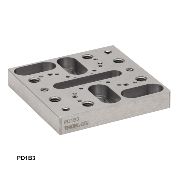
Mechanical Drawing for the PD1B3(/M) Adapter Plate. See the table on the left for descriptions of the hole labels. Dimensions for the metric version of the adapter plate are given in parentheses.

- Provide Flat Surface for Mounting ORIC Stages
- Passivated Stainless Steel Construction
- Reduces Stage Warping When Mounting to Table or Breadboard
- Dimensions (L x W x H): (65.0 mm x 65.0 mm x 10.0 mm)
Thorlabs' PD1B3(/M) Universal Adapter Plate provides a flat surface (flatness ≤5 µm) for mounting any of the ORIC piezo inertia stages. Mounting holes are labelled in the mechanical drawing to the right corresponding to the table below. The four 4-40 threaded holes are 30 mm cage system compatible, and two 1/4"-20 (M6) screws are included for mounting to breadboards.
If the stage is mounted on a surface with >5 µm flatness (as with most breadboards and optical tables), the velocity variation and pitch/yaw of the stage may suffer due to the stage warping. Mounting the stage on the adapter drastically reduces the amount the stage warps when mounted on a table or breadboard with insufficient flatness.
| Labela | Holes/Slots Patternb | Spacingb (Stage Compatibility) | Threading Depth | Places |
|---|---|---|---|---|
| A | 1/4"-20 (M6) | 1" x 2" (25 x 50 mm) | Through | 6 |
| B | Ø2 mm Dowel Pin Holes | 16 x 16 mm | 1.5 mm | 4 |
| C | #4-40 | 30 x 30 mm (Item # PDR1(/M), PDR1V(/M)) | 3.5 mm | 4 |
| D | 1/4"-20 (M6) C-Slot | 1" to 2" (25 to 50 mm) | N/A | 4 |
| E | #00-90 (M1.2) | 10 x 10 mm (Item # PD2(/M), PDX2(/M)) | 3 mm | 4 |
| F | #8-32 (M4) C-Slot | 1.25" (31.25 mm) | N/A | 1 |
| G | #2-56 (M2) | 27.0 x 23.4 mm (Item # PDXZ1(/M), PD1(/M), PDX1(/M), PD1D(/M), PD1V(/M), PDR1C(/M)) / 40.8 x 30 mm | 7 mm | 8 |
| H | #8-32 (M4) | 2" (50 mm) (Item # PD3(/M)) / 2" x 2" (50 x 50 mm) (Item # PDXR1(/M)) | 7.8 mm | 4 |

 Zoom
ZoomClick to Enlarge
Three PD3(/M) stages can be mounted in an XYZ configuration using the PD3T(/M) and PD3Z(/M) adapters.
Click for Details
PD3Z(/M) Bracket Schematic. Dimensions for the metric bracket are given in parentheses.
- Mounts PD3(/M) Stage at 90° for Vertical Translation
- Enables Vertical Z-, XZ-, or XYZ-Axis Configurations
The PD3Z(/M) right-angle bracket allows the user to mount the PD3(/M) stage at 90°. The bracket can be secured to the breadboard or top plate of the stage using two 8-32 (M4 x 0.7) cap screws in the base mounting slots. The vertical stage can be mounted on the bracket using two 8-32 (M4 x 0.7) cap screws in the mounting counterbores along the stage centerline. Four Ø2 mm dowel pin holes are located on each face for precise alignment.
Note that in an XYZ configuration, the locking plate of the bottom stage may interfere with the translation range of the vertical stage. Simply remove the locking plate to achieve the full range of translation in all three dimensions.
Note: Long-term operation (>3 billion steps) when mounted vertically may cause rail creep, leading to a reduced travel range. To restore the stage performance, we recommend mounting the stage horizontally after 1 billion steps of operation in a vertical orientation and translating it back and forth across the full travel range several times.

 Zoom
Zoom
Click for Details
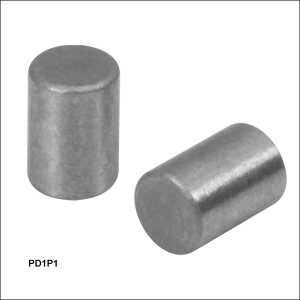
PD1P1 Dowel Pins fit into the mounting holes of most ORIC® Stages, as shown in the PD1 Stage above.
- Ø2 mm, 3 mm Long Dowel Pins
- Corrosion-Resistant Stainless Steel
- Sold in Packs of 20
The PD1P1 Dowel Pins are 2 mm in diameter and are 3 mm long. They serve as replacements for the dowel pins that are included with Thorlabs' 4.5 mm Vertical, 20 mm, 50 mm, Rotating, and Vacuum-Compatible ORIC® Stages. Composed of stainless steel, the dowel pins are corrosion-resistant.
The dowel pins are sold in packs of 20.

 Zoom
Zoom| Key Specificationsa | ||
|---|---|---|
| SMC Port | Number of Ports | Two |
| Voltage | 0 to 40 V | |
| Frequency | 20 kHz Max | |
| D-Sub Port | Number of Ports | One |
| Voltage | -10 to 50 V | |
| Frequency | 20 kHz Max | |
| Max Current Limit | 10 A | |
| Front USB | Type A, USB Host 2.0 | |
| Back USB | Type B, USB Device 2.0 | |
| Voltage of Analog In/Out | -10 to 10 V, ±2% | |
| Voltage of Trigger In/Out | 0 to 5 V, TTL | |
| Input Power | 100 - 240 VAC, 50 - 60 Hz | |
- For complete specifications, please see the manual by clicking the red Docs icon (
 ) below.
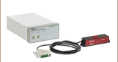
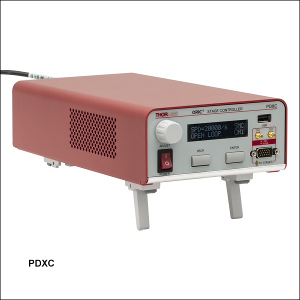
- Controller for ORIC Piezo Inertia Linear Stages, PDXZ1(/M) Vertical Stage, and both PDR1C(/M) and PDXR1(/M) Rotation Stages
- Supports Both Open- and Closed-Loop Operation
- SMC and 15-Pin D-Sub Ports Available
This controller is designed to control our ORIC piezo-inertia-driven linear stages, PDXZ1(/M) vertical stage, and both PDR1C(/M) and PDXR1(/M) rotation stages. It offers two channels that support open-loop stage control using SMC outputs and one channel that can provide open- or closed-loop stage control using a 15-pin D-sub output. If a longer connection is required for ORIC stages with a D-Sub connector, the PDXCE Extension Cable can be used (sold separately below).
Embedded software allows this unit to be fully controlled using the buttons, LCD display, and knob on the front panel. Alternatively, built-in external trigger modes support single-channel operation. By connecting multiple controllers together, multi-channel operation in D-sub mode such as a raster scan is possible. Users can select the output port(s), switch between open-loop and closed-loop modes, and perform homing and encoder calibration without being connected to a PC. In addition to these on-unit controls, USB connectivity provides simple PC-control with our available software platform.
The unit comes with a compatible region-specific power cord. For all applications, use an IEC320 compatible power cord fitted with a plug appropriate for your particular power socket. Ensure the line voltage rating marked on the rear panel agrees with your local power supply.
For more information, please see our full web presentation.

 Zoom
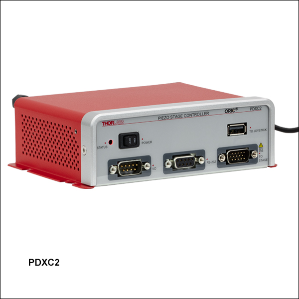
Zoom| Key Specificationsa | ||
|---|---|---|
| Performance Specificationsa | ||
| D-sub Port | Number of Ports | One |
| Voltage | 0 to 56 V | |
| Frequency | 20 kHz Max | |
| Max Current Limit | 10 A | |
| Front USB | Type A, USB HID Host | |
| Back USB | Type B, USB Device 2.0 | |
| I/O Port | Voltage of Analog In/Out | -10 to 10 V, ±2% |
| Voltage of Trigger In/Out | 0 to 5 V, TTL | |
| Ethernet PC Communication | One RJ-45 Port | |
| Dimensions (L x W x H) | 115.2 mm x 150.0 mm x 48.5 mm (4.54” x 5.91” x 1.91”) |
|
| Weight | 0.53 kg | |
| Input Power | 12 V, 3 A DAC | |
- For complete specifications, please see the manual by clicking the red Docs icon () below.
- Controller for ORIC Piezo Inertia Linear Stages, PDXZ1(/M) Vertical Stage, and both PDR1C(/M) and PDXR1(/M) Rotation Stages
- Compact Design and PC Control with Kinesis® Software
- Supports Both Open- and Closed-Loop Operation
- Energy Efficient Switch Amplifier Circuit Outputs Peak Current of 10 A
- Configurable High Speed Communication Interfaces: USB 2.0, Gigabit Ethernet, Digital I/0, Analog I/0
- 800 Hz to 20 kHz Pulse Rate Range
The PDXC2 compact controller is designed for our ORIC piezo-inertia-driven linear stages, PDXZ1(/M) vertical stage, and both PDR1C(/M) and PDXR1(/M) rotation stages. It features one channel that supports open- or closed-loop stage control using a 15-pin D-sub output. The PDXC2AD D-sub to SMC adapter cable can be used to operate stages with an SMC connection in open-loop mode.
The PDXC2 controller is connected to PC by either the USB or ethernet ports on the back panel of the controller. All the operating parameters and operations, such as switching between open- and closed-loop modes, performing homing operation, and parameter optimization are controlled by PC with the Kinesis® software (available for download on the Kinesis Software tab above). Settings such as trigger modes and movement parameters can be configured for operations such as raster scans. Calibration for specific ORIC stages with encoders (Item #s PDX1(/M) and PDXR1(/M) only) is performed with the PDXC2 Calibration Tool found on the Motion Control Software page. Please see the user manual for details. Command-line control is also possible through the USB and RS-232 ports.
The PDXC2 unit is powered by the included DS12 12 VDC power adapter, which operates at an input voltage of 100 - 240 VAC and ships with a region-specific AC cable. For all applications, use an IEC320 compatible power cord fitted with a plug appropriate for your particular power socket. Make sure that the line voltage rating marked on the power adapter agrees with your local power supply.
For more information, please see our full web presentation.

 Zoom
Zoom
Click to Enlarge
DB15 Male to DB15 Female
Click to Enlarge
Mechanical Drawing
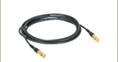
- Connects Male D-Sub Connector on a PDXZ1(/M), PD2(/M), PDX2(/M), PDX1(/M), PD3(/M) or PDXR1(/M) Stage to PDXC or PDXC2 Piezo Inertial Stage Controller
- 3000.0 mm (118.11") of Extra Length
The PDXCE extension cable can connect the PDXZ1(/M) 4.5 mm vertical travel stage; the PD2(/M) 5 mm, PDX2(/M) 5 mm, PDX1(/M) 20 mm, PD3(/M) 50 mm linear piezo inertia stages; or the PDXR1(/M) rotation stage to the PDXC or PDXC2 ORIC Inertia Stage Controller. The cable provides 3000.0 mm (118.11") of extra cord length if needed.

 Zoom
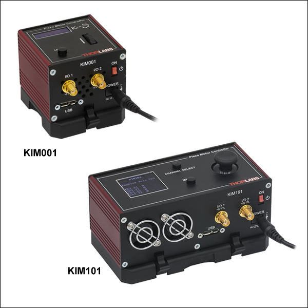
Zoom| Key Specificationsa | ||
|---|---|---|
| Item # | KIM001 | KIM101 |
| Piezoelectric Outputs (SMC Male) | One | Four |
| Piezo Output Voltage | 85 to 125 VDC | 85 to 125 VDC per Channel |
| Top Panel Controls | Scroll Wheel | Dual-Axis Joystick |
| External Input (SMA Female) |
±10 V ± 2% | |
| Input Power | +15 VDC @ 2 A | |
| Housing Dimensionsb |
60.0 mm x 60.0 mm x 47.0 mm (2.36" x 2.36" x 1.85") |
121.0 mm x 60.0 mm x 47.0 mm (4.76" x 2.36" x 1.85") |
| Compatible Software | Kinesis | |
| Compatible Piezo Inertia Stagesc |
5 mm Linear Stage, 20 mm Linear Stages, 50 mm Linear Stage, & Rotation Stages |
|
- For complete specifications, please see the manuals by clicking the red Docs icons () below.
- Not Including Mounting Plate
- Compatibility with the PD2(/M) 5 mm and PD3(/M) 50 mm stages require the PD2AD adapter cable. The KIM001 and KIM101 controllers are not compatible with the PDX1(/M) Linear Stage with Optical Encoder.
- Compact Footprints
- Adjustable Voltage Output from 85 V to 125 V
- Single-Channel and Four-Channel Versions Available
- Standalone Operation via Top Panel Controls and Display or PC Control via USB Plug and Play
- See Table for Compatible Stages
These compact K-Cube Controllers provide easy manual and PC control of our piezo inertia stages that use SMC connectors, piezo inertia actuators, and optic mounts. They are also compatible with our PD2(/M) 5 mm or PD3(/M) 50 mm linear stages when used with a PD2AD adapter cable (sold separately). The controllers feature adjustable voltage output from 85 V to 125 V. The top panel display screen enables operation as soon as the unit is turned on, without the need for connection to a PC. Alternatively, both controllers have USB connectivity that provides 'Plug-and-Play' PC-controlled operation with our Kinesis® software package (included).
These units have small footprints and may be mounted directly to the optical table using the 1/4" (M6) counterbored slots in the base plate. Their compact size allows these controllers to be positioned close to the motorized system for added convenience when manually adjusting motor positions using the top panel controls. Tabletop operation also allows minimal drive cable lengths for easier cable management.
KIM001 Single-Channel Controller
This single-channel piezo inertia controller provides a voltage output for a single piezo inertia stage or actuator. The top panel features a spring-loaded scroll wheel for driving the stage or actuator as well as selecting menu options.
KIM101 Four-Channel Controller
This four-channel controller features four SMC outputs to drive piezo inertia devices. The channels can be controlled independently or simultaneously in pairs using the dual-axis joystick on the controller's top panel. The controller can be configured to operate up to four PD series piezo inertia stages, up to four PIA series piezo inertia actuators, or up to two PIM series piezo inertia optic mounts; one KIM101 can only concurrently drive devices that use the same "Select Stage" configuration in the controller's menu options (see the manuals for more details).
For more information, please see the full web presentation.
Operation
Set the stage configuration on the KIM001 or KIM101 controller to "PD(R)" before driving this stage. Select the "Select Stage" option, change it from "PIA" to "PD(R)", and then restart the controller. The display will show "Stage is PD(R)" and the configuration will be changed to drive the ORIC PD Series stage. For additional front panel configuration details, please see the KIM001 or KIM101 controller manuals by clicking the red Docs icons () below. These drivers have an internal sawtooth voltage signal generator capable of sending sub-millisecond pulses (steps) with controllable amplitudes from 85 V to 125 V.
Power Supply
The KIM001 and KIM101 Motor Controllers do not ship with a power supply. The compatible KPS201 Power Supply is sold separately below.
Note: Due to the nature of its design, and its non-linear high frequency switching, the KIM001 and KIM001 units are not compatible with the KCH301 and KCH601 hubs. Only use the KPS201 power supply unit. These controllers are also not compatible with the PDX1(/M) stage. Compatibility with the PD2(/M) 5 mm and PD3(/M) 50 mm stages require the PD2AD adapter cable.
 or PD3(/M) Stage to KIMx01 Controller Adapter Cable")
 Zoom
Zoom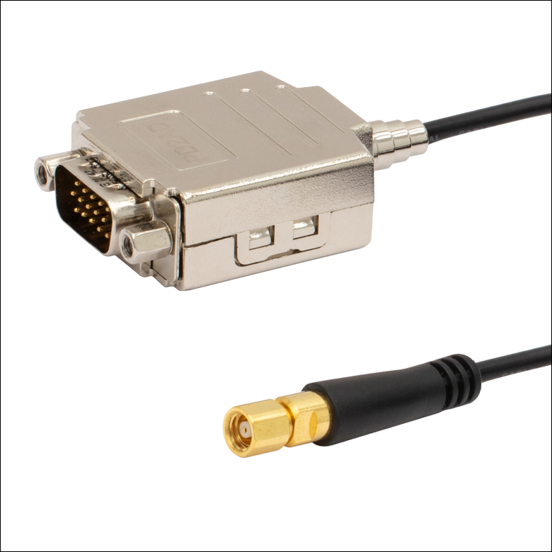
Click to Enlarge
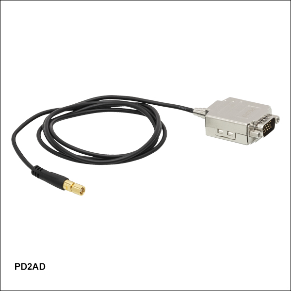
DB15 Male to SMC Female
Click to Enlarge
Mechanical Drawing
- Adapts Male D-Sub Connector on a PD2(/M) or PD3(/M) Stage to an SMC Female Connector
- 50 Ω Impedance
- RG174/U Coaxial Cable
The PD2AD piezo drive cable is required to drive the PD2(/M) 5 mm or PD3(/M) 50 mm linear piezo inertia stages using the KIM001 or KIM101 K-Cube controllers.
Note that the D-sub connector's Pin 12 is connected to the outer shield of the SMC connector, while Pin 13 is connected to the SMC core wire.

 Zoom
Zoom- Power Supply Compatible with KIM001 and KIM101 Motor Controllers
- Universal Input: 100 - 240 VAC
- Region-Specific Adapter Plug Shipped with Power Supply
The KPS201 power supply outputs +15 VDC at up to 2.66 A and can power a single K-Cube or T-Cube with a 3.5 mm jack. It plugs into a standard wall outlet. One region-specific plug adapter, selectable at checkout, is included with each power supply.