 Products Home / Motorized Stages / Motorized Linear Stages / Motorized 50 mm (1.97") Linear Translation Stages / 50 mm (1.97") Compact Motorized Translation Stage
50 mm (1.97") Compact Motorized Translation Stage
- 50 mm (1.97") of Travel in a Low-Profile Package
- 8-32 (M4 x 0.7) and 4-40 (M3 x 0.5) Tapped Holes
- Mounting Adapters for Breadboards, Multi-Axis Motion, and 60 mm Cage Systems
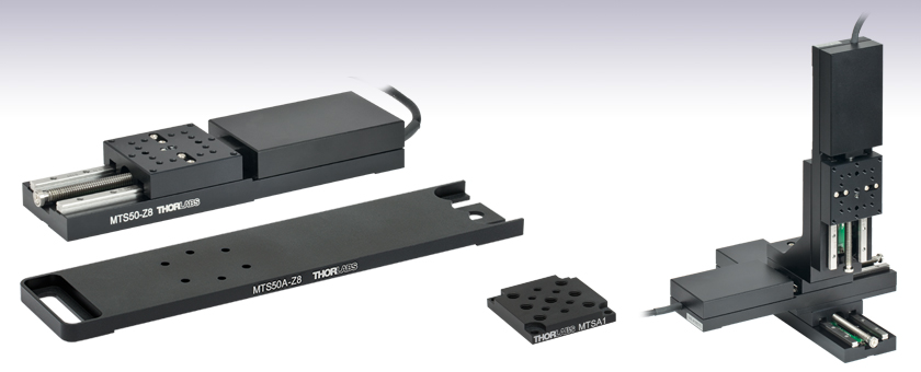
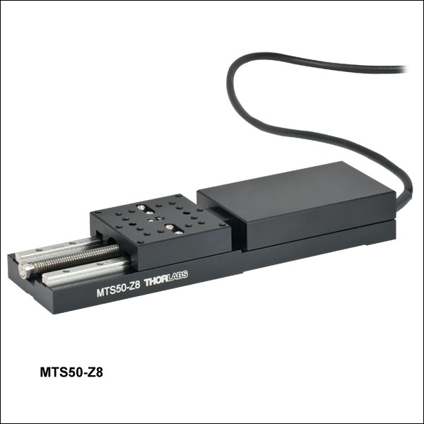
MTS50-Z8
50 mm Stage
MTS50A-Z8
Breadboard Mounting Adapter
MTSA1
Accessory Mounting Plate
1/4"-20 (M6) and 8-32 (M4) Taps
Application Idea
Three MTS50-Z8 Stages
in XYZ Configuration,
Using an MTS50B-Z8
Adapter Plate and
MTS50C-Z8 Bracket


Please Wait
| Key Specificationsa | |
|---|---|
| Travel Range | 50 mm (1.97") |
| Velocity (Max) | 2.4 mm/s |
| Min Incremental Movementb | 0.8 µm |
| Repeatabilityc | 15 µm |
| Backlashd | <6 µm |
| Horizontal Load Capacity (Max) | 25 lbs (12 kg) |
| Vertical Load Capacity (Max) | 10 lbs (4.5 kg) |
| Included Actuator | Built-In DC Servo |
| Cable Length | 0.5 m (1.6 ft) |
| Required Controller | KDC101 |
Features
- 50 mm (1.97") Travel Range
- Carriage Contains One Centered 8-32 (M4 x 0.7) Tap and Eighteen 4-40 (M3 x 0.5) Taps
- Low-Profile Package Combines Actuator and Moving Platform
- DC Servo Motor Actuator
- Several Mounting Adapters Available
- Base Plate for Breadboard Mounting
- Mounting Adapter Plate for Standard Optical Accessories, Provides Seven 1/4"-20 (M6 x 1.0) and Six 8-32 (M4 x 0.7) Tapped Holes
- XY Mounting Adapter
- Right-Angle Bracket for Vertical Mounting
- Adapter for 60 mm Cage Systems
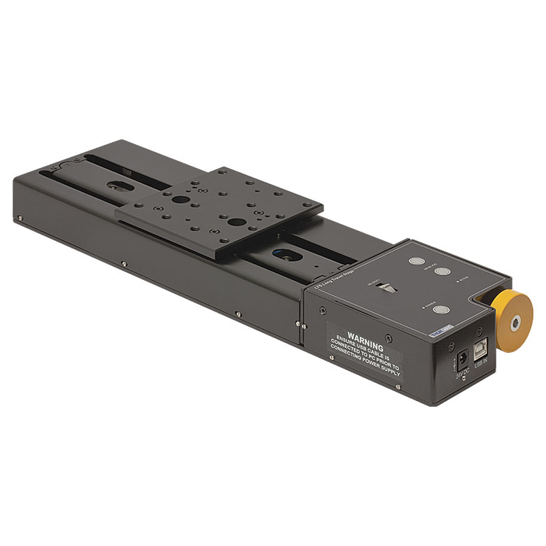
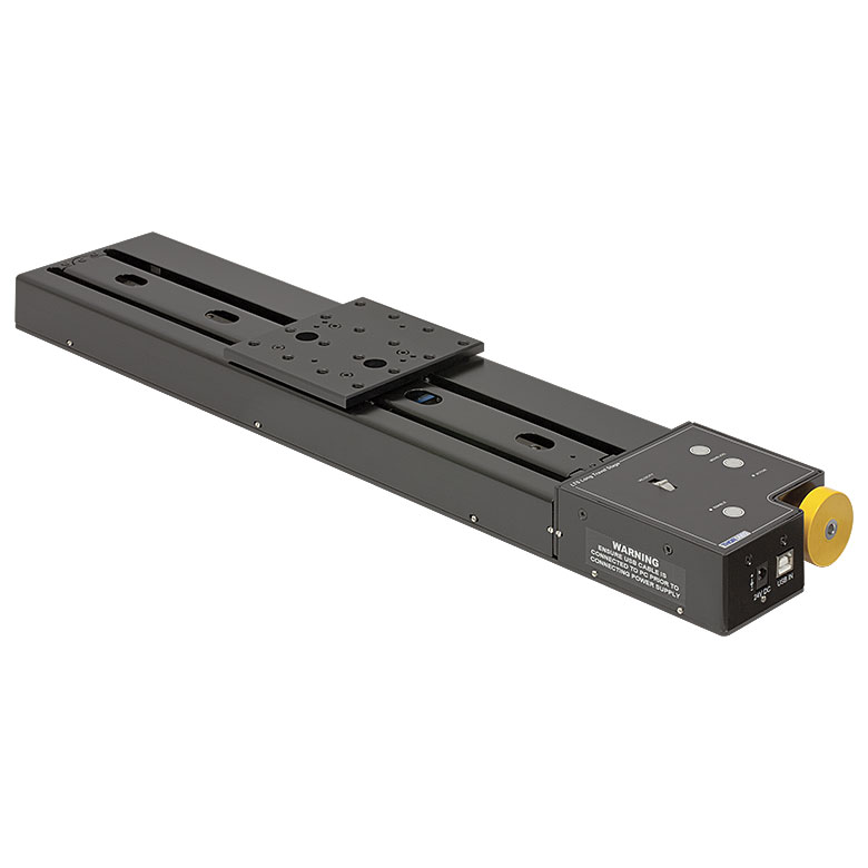
Thorlabs' MTS50(/M)-Z8 Motorized Translation Stage features 50 mm (1.97") of electronically controlled linear travel along a well-defined axis. Each stage is equipped with a 1.50" x 1.50" (37.5 mm x 37.5 mm) tapped hole matrix that includes eighteen
The moving platform contains holes for alignment pins that ensure orthogonality when the stage is stacked with other stages or connected to our accessories. Horizontal loads of 25 lbs (12 kg) and vertical loads of 10 lbs (4.5 kg) are supported by the 67.49:1 planetary gear head. A built-in Hall Effect encoder provides a resolution of 29 nm (see the Specs tab for additional details).
The translation mechanism, based upon a dual set of linear rails with continuously recirculating ball bearings, provides smooth, low-friction movement. Built-in limit switches prevent travel outside of the intended range, regardless of the control interface being used.
Mounting Adapters and Stage Combinations
Thorlabs' adapter plates and brackets provide a convenient way to mount the MTS50(/M)-Z8 stage on an optical table or breadboard; to install a motor along the optical axis of our 60 mm cage systems; and to allow several stages to be combined in XY, XZ, or XYZ configurations. A multi-hole adapter plate is also available that offers seven 1/4"-20 (M6 x 1.0) and six 8-32 (M4 x 0.7) tapped holes, providing more options when mounting standard optical accessories to the top platform. Our MTS25-Z8 25 mm (0.98") Motorized Translation Stage can also be combined with the MTS50(/M)-Z8 in certain arrangements. All these uses are described in greater detail below.
Controller Options
The KDC101 DC Servo Motor Controller is required to operate the stage and is sold separately below. Alternatively, we offer the KMTS50E(/M) bundle, which includes the MTS50(/M)-Z8 translation stage, the KDC101 DC Servo Controller, and a KPS101* power supply at a significant savings over ordering these items separately.
The KDC101 controller provides control for a single axis, with or without a PC. The unit is fully compatible with our Kinesis and XA software packages, which supply out-of-the-box stage control from a PC and enable support for common programming interfaces like LabVIEW and LabWindows. Please see the Kinesis and XA Software tab for more information. A USB cable is included with the KDC101.
Thorlabs also manufactures the LNR502(/M) Motorized Stage, which features a larger mounting surface for even more flexibility.
*This previous-generation item is not available for individual purchase. If a replacement is needed, the KPS201 Power Supply can be used.
| Stage Specifications | |
|---|---|
| Translation | |
| Travel Range | 50 mm (1.97") |
| Repeatabilitya | 15 µm |
| Backlashb | <6 µm |
| Theoretical Min Incremental Movementc | 0.03 µm |
| Min Incremental Movementd | 0.8 µm |
| Accuracy | 100 µm |
| Homing Accuracy | ±4.0 µm |
| Motion Parameters | |
| Speed | 2.4 mm/s Max |
| Acceleration | 4.5 mm/s2 Max |
| Load Capacity | |
| Vertical Load | Recommendede: <4.0 kg (<8.8 lbs); Max: 4.5 kg (10 lbs) |
| Horizontal Load | Recommendede: <10 kg (<22 lbs); Max: 12 kg (25 lbs) |
| Straightness | |
| Pitch | 873 µrad |
| Yaw | 500 µrad |
| Motor Specifications | |
| Motor Type | DC Servo |
| Motor Drive Voltage | 6 VDC |
| Feedback | Hall Effect Encoder |
| Encoder Resolution | 29 nm |
| Encoder Counts per Lead Screw Revolution | 34,555 |
| Planetary Gear Head Ratio | 67.49:1 |
| Cable Length | 0.5 m (1.6 ft) |
| General Specifications | |
| Dimensions | 6.33" x 1.69" x 0.87" (160.8 mm x 43.0 mm x 22.0 mm) |
| Weight | 0.35 kg (0.76 lbs) |
Encoder Resolution Calculation
For the MTS50-Z8 (MTS50/M-Z8), there are 512 encoder counts per revolution of the motor. The output shaft of the motor goes into a 67.49:1 planetary gear head. This requires the motor to rotate 67.49 times to rotate the 1.0 mm pitch lead screw one revolution. The end result is the lead screw advances by 1.0 mm.
The linear displacement of the actuator per encoder count is given by
512 x 67.49 = 34,555 encoder counts per revolution of the lead screw,
whereas the linear displacement of the lead screw per encoder count is given by
1.0 mm / 34,555 counts = 2.9 x 10⁻⁵ mm (29 nm).
Motor Connector
D-Type Male
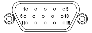
| Pin | Description | Pin | Description |
|---|---|---|---|
| 1 | Ground/Return | 9 | Reserved for Future Use |
| 2 | Forward Limit Switch | 10 | Vcc |
| 3 | Reverse Limit Switch | 11 | Encoder A |
| 4 | Reserved for Future Use | 12 | Reserved for Future Use |
| 5 | Motor - | 13 | Encoder B |
| 6 | Reserved for Future Use | 14 | Ident |
| 7 | Motor + | 15 | Ident |
| 8 | Reserved for Future Use |
Software
Kinesis Version 1.14.58
XA Version 1.6.0
The Kinesis and XA Software Packages, which include a GUI for control of Thorlabs' motion controllers.
Also Available:
- Firmware Update Utilities
- Communications Protocol

Figure 789A Kinesis GUI Screen
Thorlabs offers two platforms to drive our wide range of motion controllers: our XA software package and our Kinesis software package, which is being phased out. The Kinesis software supports most of Thorlabs' motion control products. The XA software is an improved platform for developers that currently supports some of our most popular motion control products (see the full list of supported products here). The software is undergoing continuous, intensive development and will eventually add support for our entire line of motion control products. The XA software application will be fully supported through the year 2040.
Kinesis Motion Control Software
The Kinesis software features .NET controls which can be used by 3rd party developers working in the latest C#, Visual Basic, LabVIEW™, or any .NET compatible languages to create custom applications. Low-level DLL libraries are included for applications not expected to use the .NET framework. A Central Sequence Manager supports integration and synchronization of all Thorlabs motion control hardware.
By providing a common software platform, Thorlabs has ensured that users can easily mix and match any of the Kinesis controllers in a single application, while only having to learn a single set of software tools. In this way, it is perfectly feasible to combine any of the controllers from single-axis to multi-axis systems and control all from a single, PC-based unified software interface.
Click to Enlarge
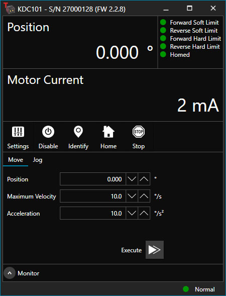
Figure 789B XA GUI for KDC101 Brushed DC Servo Controller
The software package allows two methods of usage: graphical user interface (GUI) utilities for direct interaction with and control of the controllers out of the box, and a set of programming interfaces that allow custom-integrated positioning and alignment solutions to be easily programmed in the development language of choice.
XA Motion Control Software: Improved Platform for Developers
Designed from the ground up to be straightforward to understand, XA provides a thread-safe and language-paradigm-agnostic set of application programming interfaces in C, C++, and C#/.NET with language wrappers available to allow for easy integration into your native, .NET language, Python, or LabVIEW applications. This enables the same functionality as mentioned for the Kinesis software development kit (SDK) while providing a more streamlined toolkit for developers. Coupled with the included developer guides and code examples in the SDK, this software is tailored toward users interested in creating complex, customized applications and interfaces. Full API documentation is provided for the native C library, and the .NET wrapper documentation is currently under development. Please contact Tech Support for more details on using the .NET wrapper.
XA also features a comparable GUI to Kinesis while adding improvements to the user experience, like the ability to save device states and a more consistent interface across devices of different types. In addition, further improvements are planned as XA will be fully supported through the year 2040, whereas the Kinesis software is being phased out. The current version of the XA software can only drive select Thorlabs motion controllers. However, the software is undergoing continuous, intensive development and will eventually add support for our entire line of motion control products. Information on software compatibility can be found in the XA User Guide, and additional details about the software, including a list of compatible devices, can be found here.
| Posted Comments: | |
Minjae Kim
(posted 2025-01-07 17:57:48.343) Could you let me know the repeatability of a linear stage during homing? Specifically, I am curious about how much the coordinates set to 0.0000 mm differ with each homing process. dnewnham
(posted 2025-01-15 10:59:38.0) Thank you for your inquiry, the home location accuracy is ±4.0 µm. This and additional information on the specifications of this device can be found under the specs tab on the webpage Jacob Osecheck
(posted 2024-10-22 10:57:13.267) What regular maintenance should be done on the linear stage MTS50-Z8? How often should it be done and do you have a document with instructions? spolineni
(posted 2024-10-29 12:03:45.0) Thank you for your inquiry. Under lab conditions, no regular maintenance is required for the MTS50-Z8 linear stage. I will personally reach out to discuss if you need any further assistance. Emeric Biver
(posted 2024-07-26 13:43:21.87) I want to use this MTS50/M-Z8 stage with a KDC101, but on a platform running on LINUX (Toradex card). I realized that the .NET framework might not be compatible. Is it the case? What would a solution be? If incompatible, can I control the MTS50/M-Z8 stage with another, LINUX-compatible controller? do'neill
(posted 2024-07-31 04:22:52.0) Thank you for your feedback. You are correct in the fact that our DLLs do not work with Linux, we do not have an official way for this to work currently but we are actively working on Linux support. I will reach out to you directly to discuss options here. ligenglin ligenglin
(posted 2024-01-03 15:13:42.233) I encountered the error "An error occurred attempting to load the assembly" when calling "Thorlabs. MotionControl. Controls. DLL" using labview. What should I do? do'neill
(posted 2024-01-05 07:49:48.0) Response from Daniel at Thorlabs. There are several things that could be the cause of this, I will reach to you directly to discuss this with you. Igor Thommen
(posted 2023-10-23 06:21:19.05) Dear all
I need for the design the KMTS50E/M as a Step...
Can you please provide it asap?
Many thanks in advance...
best regards
Igor
Sensirion AG mdiekmann
(posted 2023-10-24 04:28:28.0) The step files are available for download for the individual components that are part of this kit on the website:
https://www.thorlabs.com/thorproduct.cfm?partnumber=MTS50/M-Z8
https://www.thorlabs.com/thorproduct.cfm?partnumber=KDC101
We are also happy to send these to you by email. Since you opted not to be contacted, please reach out to europe[at]thorlabs.com if you need additional assistance. Stavros Zogas
(posted 2023-04-15 13:29:54.1) Hi!
Can we implement "on the fly" velocity changes on MTS50-Z8 with kdc 101 controller? . We want to send a new move command while the current move is in progress and the controller to transition to the new move parameters without stopping.
Best regards fguzman
(posted 2023-04-17 11:38:37.0) Thanks for contacting Thorlabs. The commands for our motor stages, are sequential. This means that the motor first the performs a motion, stops for a short period of time and then performs the next command. Geoffrey Farmer
(posted 2022-07-22 13:18:58.99) Just to clarify one of the specifications.
The resolution is stated as 29nm
The absolute accuracy is 290um
What is the relative accuracy of measurement
ie If i start from a position at one end of the travel and then drive 10mm or 45mm and stop, how accurately will I know the new position.
(Note, inaccuracy in the achieved position is not an issue if I know accurately where I am)
Thank you cwright
(posted 2022-07-25 08:14:05.0) Response from Charles at Thorlabs: Thank you for your query. The resolution is the smallest incremental change the controller can see and is the determined from the pitch of the lead screw divided by the number of encoder counts per revolution of this screw. The absolute accuracy is the maximum discrepancy between command position and absolute position over the full travel of the stage. More relevant to you is the percentage accuracy, which is the maximum discrepancy between command position and absolute position expressed as a percentage of the commanded position and gives a better idea of what to typically expect along a stage's travel. Ivan Zorin
(posted 2022-05-12 07:33:04.87) Dear Madam or Sir,
I have a question about MTS50/M-Z8.
The system we have, for some reason, moves only in one direction. The move in the back direction does not work (so it is stuck in the extreme position with the full opening). The problem is observed in both manual operations and in the software. The controller is standard TDC001.
What can be a problem?
Best regards,
Ivan Zorin cwright
(posted 2022-05-12 08:35:08.0) Response from Charles at Thorlabs: Thank you for contacting us. There could be multiple causes for this, resulting from the firmware, control electronics or the mechanism of the actuator. The most common cause would be that the stage has become stuck on an end stop. This can happen when, rather than moved to a position, it is driven forward at speed beyond the limit of travel. We will reach out to you to help with troubleshooting your device. Parker Roberts
(posted 2022-03-16 13:35:00.203) Hello, I have a question about the linear bearings on these motion stages. Do they use grease? I would like to implement these in a cryogenic vacuum system where greased motors could fail. DJayasuriya
(posted 2022-03-18 09:19:46.0) Thank you for your inquiry. Yes the MTS uses a grease, if this was used in a cryogenic vacuum special grease and cabling would be needed. Also the anodisation will outgasses as well. So wold not recommend to be used in a cryogenic vacuum system. user
(posted 2022-01-20 12:58:18.483) Hi, I have acquired the two stages and all supporting parts and plan on putting them together in an XY configuration. I am using Visual Basic as my programming environment. I'm a little confused how to begin though. I have looked through the APT tutorials and read everything about APT, Kinesis, and the KCube. Is there anything else I can read or watch to help guide me? DJayasuriya
(posted 2022-01-24 04:00:51.0) Thank you for your inquiry. I wonder if you have seen Kinesis with C# manual :https://www.thorlabs.de/Software/Motion%20Control/KINESIS/Kinesis%20with%20C%20Quick%20Start%20Guide.pdf
Please get in touch with our techsupport team if you have any question we would be happy to help. DJayasuriya
(posted 2022-01-24 04:00:51.0) Thank you for your inquiry. I wonder if you have seen Kinesis with C# manual :https://www.thorlabs.de/Software/Motion%20Control/KINESIS/Kinesis%20with%20C%20Quick%20Start%20Guide.pdf
Please get in touch with our techsupport team if you have any question we would be happy to help. Wenqiang Zheng
(posted 2021-06-08 23:05:56.053) Hi,
We found the motorized stage squeaked recently. Do you have some suggestion to get rid of it? We would like to use lubricating oil, but we are not sure which kind of oil is suitable.
Best,
Wenqiang Zheng DJayasuriya
(posted 2021-06-09 11:03:37.0) Thank you for your inquiry. We have reached out to you directly with the grease that we use. Christian Maibohm
(posted 2020-08-05 11:29:08.33) Dear Thorlabs,
Can you control the MTS50/M-Z8 stage with micro-manager?
Best regards, Christian Maibohm cwright
(posted 2020-08-10 08:56:13.0) Response from Charles at Thorlabs: Hello Christian and thank you for contacting us. Unfortunately the ThorLabs modules created for our APT-Compatible stages were not developed by us and we do not know how these are set up. Based on the list of Device Support on Micromanager's website, it does not appear that the KDC101 controller, which would be required to control this stage, has been implemented. seunggi Jung
(posted 2020-07-28 04:20:43.44) Hello, Thorlabs.
MTS50-Z8 Mounted in 3-Axis XYZ Array
I don't know how to use the software after installing the product.
We are moving the axis manually.
I would appreciate it if you could give me feedback on how to use the document (drawing).
Well, thank you very much. DJayasuriya
(posted 2020-08-05 04:31:18.0) Thank you for your inquiry.After installing the motion control software Kinesis (https://www.thorlabs.com/software_pages/ViewSoftwarePage.cfm?Code=Motion_Control&viewtab=0), if you go into the downloaded directory you will find a help file named 'Thorlabs.MotionControl.KinesisHelp'. This would help guide you through the software. If you have further question please don't hesitate to get in touch with your local tech support team for help directly. Rachid Sbiaa
(posted 2020-05-24 16:31:13.977) I need to buy MTS50-Z8 translation stage and hold it with MTS50C-z8. The problem is I nee the translation stage to be a little high. Can you put a hole at the base of MTS50C so I can use a post to hold it higher? DJayasuriya
(posted 2020-05-27 04:07:28.0) Thank you for your inquiry. We will get in touch with you directly to discuss your application. t t
(posted 2020-01-30 05:36:53.47) Hello, there is statement in details that Absolute On-Axis Accuracy is 290 µm. Is that correct? seems quite large value compared to other specs DJayasuriya
(posted 2020-02-11 05:38:04.0) Response from Thorlabs: Hello, thank you for your enquiry. This is due to the lead screw of the unit having some imperfections and the configuration of the gear box ratio that causes the on axis accuracy spec. Hope this helps clarify your question. Ahsanul Torza
(posted 2019-12-19 12:56:40.1) I am running this stage in a 3-axis configuration using the MG17 motors. When I run my labview code in any direction the motor allows the stage to move smoothly In one direction but when it starts moving towards the other direction it jerks which causes a problem in all of my data collecting. This happens in all the axis, thanks and hope to hear back soon user
(posted 2019-12-20 08:28:00.0) Response from Charles at Thorlabs: Hello Ahsanul, thank you for letting us know you are having trouble. It sounds like this could be the result of a sharp change in acceleration and may be solved by altering the velocity profile. Since troubleshooting could require seeing your VI, and a bit of back and forth, a member of our technical support team will reach out to you directly to assist with this. Lindsey Barner
(posted 2019-08-08 03:25:51.06) Hi, I purchased an MMTS50-Z8 stage and its respective controller a few months ago, and I was wondering if I could return the item because it is faulty. When translating, it experiences a very obvious wobble that is out of spec. Let me know, thanks so much! Lindsey Barner rmiron
(posted 2019-08-08 06:02:08.0) Response from Radu at Thorlabs: Hello Lindsey. Because the lead screw is unsupported at one end and because of imperfections in the manufacturing process, the lead screw of MTS50-Z8 wobbles. This wobbling is usually visible with the naked eye, but does not affect the performance of the stage. We still test whether the stage meets the specs listed on the website before stocking it. While we do not post a spec for the max wobbliness of the lead screw, we do post straightness and on-axis accuracy specs that in theory could be affected by an unusually wobbly lead screw. If you find that the stage changes its position by more than 50 um in a direction perpendicular to the travel direction, you are entitled to a replacement. The same holds true if the accuracy specs are not met (absolute & percentage accuracy). If that is the case, please contact your local technical support office, provide them the specs you have measured and a description of how they were measured and ask for a replacement. Alternatively, we could take the stage back for a free of charge evaluation. tomrumx
(posted 2018-09-19 17:52:15.82) hello, i have three mts50-z8 stages, but APT user program and also kinesis recognize one properly but two others as "Z606(B)" and gives them wrong speeds etc. How to program stages to have factory defaults ? AManickavasagam
(posted 2018-09-20 09:52:50.0) Response from Arunthathi @ Thorlabs:Thanks for your query.
There might be a possibility that the stage was used with a different controller previously and the settings were persisted accordingly.
Please could you unintall any older versions of Kinesis (to avoid communication errors) and install the newest version of Kinesis from the website and run the firmware update utility which you should find in this location C:\Program Files (x86)\Thorlabs\Kinesis\Firmware Update Utility.
If your PC is able to detect the stages (seen in control panel->device manager) then the connection/hardware should probably be fine and this might possibly be a firmware issue, by doing the above the issue you have may be resolved. Please do contact us directly if your issues persist. droy
(posted 2018-05-18 16:45:15.83) Hello, I am trying to use your Kinesis Labview guide to run the MTS50-Z8. When I select The Thorlabs.MotionControl.Controls.dll in the .NET control, a long list of compatible Kinesis controls is displayed. What control should I select corresponding to MTS50-Z8? I looked up the Thorlabs.MotionControl.DotNet_API help file, and the model MTS50-Z8 is not listed. Thanks bhallewell
(posted 2018-05-22 03:09:33.0) Response from Ben at Thorlabs: Thank you for your question. Our programming APIs refer typically to the controller being used as opposed to the stage. In this case, MTS50-Z8 is driven by the KDC101 controller, or our legacy variant - TDC001. Within the .NET API, you will find the Contents lists these Controllers with descriptions of relevant Namespaces, Methods & Properties. kori.macdonald10
(posted 2014-05-19 14:16:45.6) Thank you for your feedback. How do I go about getting the correct configuration set in APT config? This software does not recognize any motors that are connected to the computer most of the time, and I do all of my control through LabView. I am looking for any way to get the stage to move into the currently negative range. Thank you. jlow
(posted 2014-07-29 03:13:12.0) Response from Jeremy at Thorlabs: There's no auto recognition of the stage in the software at the moment. You set up the stage in APT Config under the "Stage" tab. We will e-mail you to provide more details specific to your setup. user
(posted 2014-05-15 16:00:35.883) Hello, I am using LabView to control this linear stage (MTS50-Z8, using MoveAbsolute). The stage will not accept negative values despite the range of the stage being from -16 to 26 (or thereabouts). Do you know how to make the stage move to a negative value using LabView commands? Thank you. msoulby
(posted 2014-05-19 04:28:07.0) Response from Mike at Thorlabs: When using the MoveAbsolute command it will always use the absolute position of the stage, for the MTS50 this range is 0-50mm where 0mm is the home position. It is always a good idea to home the stage first to set this absolute reference datum for the stage. With the correct configuration set in APT config you should not need to enter any negative values. Kyle.Epp
(posted 2014-02-07 12:34:42.21) What is the axial (vertical) load capacity when the stage is mounted vertically? Will it be the same as the axial (horizontal) load capacity when the stage is mounted horizontally or how much is it affected by gravity? msoulby
(posted 2014-02-10 03:56:22.0) Response from Mike at Thorlabs: The horizontal load capacity for the MTS50/M stages is 12kg. For a vertically mounted stage the load capacity reduces to just 4.5kg. benjamin.r.anderson
(posted 2013-12-17 17:58:43.38) for the LNR50S it has the minimum increment as 0.1um, but with the inclusion of the controller the increment becomes 1um. Why? and is there a controller that can get the 0.1um? or do you need to have the encoded version msoulby
(posted 2013-12-18 04:05:28.0) Response from Mike at Thorlabs: The minimum achievable incremental movement possible with the LNR50S and encoded version LNR50SE is 0.05um. The minimum repeatable incremental movement is 1um for the non-encoded version of the stage LNR50S and 0.1um for the encoded version of the stage LNR50SE. All of these specifications can be found on the ‘Specs’ tab on the product webpage. We will contact you directly to discuss some potential solutions for your application. benjamin.r.anderson
(posted 2013-12-17 17:55:41.627) With the included controller what is the minimum step size? msoulby
(posted 2013-12-18 03:50:55.0) Response from Mike at Thorlabs: The minimum increment is specified as 0.1um however the minimum increment that can be reliably repeated with the TDC001 and MTS50/M-Z8 is 0.8um.
To achieve a minimum increment of 0.1um you should consider the following options:
1) The LNR50SE/M + BSC201 controller, this encoded stage and controller combination will allow you to achieve a minimum repeatable increment of 0.1um and a bidirectional repeatability of 0.3um.
2) The DDS220/M + BBD201 controller, this direct drive linear stage utilises a linear optical encoder allowing a minimum increment of 0.1um and bidirectional repeatability of 0.25um, it also has the added benefit of having zero mechanical backlash as there are no mechanical parts, such as lead screws or gears in the stage. user
(posted 2013-04-17 14:54:47.523) achievable is misspelled on the specs section. sharrell
(posted 2013-04-17 15:11:00.0) Response from Sean at Thorlabs: Thank you for pointing out the error. We have corrected the misspelling. abrachucha
(posted 2013-03-12 00:12:33.507) Hi. I currently have a MTS50-Z8 working with a 3-axis configuration with its corresponding TDC001. All have been working out fine till today when I set the motor to make a single step. The motor started working and stopped when the screw's string reached its end. At the same time, on the APT User monitor the zero position was displayed, regardless of the movement of the motor.
Why is this happening? What can I do? Does the warranty attend this defect?
I have no made any misuse with the motor, and there is no reason for this to happen.
Thanks jlow
(posted 2013-03-13 11:54:00.0) Response from Jeremy at Thorlabs: We will get in contact with you on troubleshooting this. jjurado
(posted 2011-05-20 15:53:00.0) Response from Javier at Thorlabs to florent.cosandier: Thank you very much for contacting us. It is possible that LabVIEW is looking to execute a command before the previous command has been fully executed. It may be recommendable to use the GetStatusBits_Bits method before the beginning of a new command in order to ensure that the translation stage is ready for its next move. You can find the description of this method in Start > Thorlabs > APT > Help > APT Server Help. I will contact you for further support. florent.cosandier
(posted 2011-05-20 08:45:19.0) Hello,
Im trying to drive the stage through Labview and in the same time to acquire a signal in a loop (in the same labview programm), but when the stage is moving the programm freezes and the loop is stoping. Do you have a hint to solve this problem? Thank you user
(posted 2010-07-13 11:29:20.0) A response from Oli at Thorlabs to Graham:
The encoders are digital pulse outputs which work as a quadrature output.
Yes, 5 VDC to pin 10 should be applied to Vcc.
The limit switch pins are wired such that they are literally switches that close when actuated by the stage, the return is pin 1 (ground) for both. graham
(posted 2010-07-10 11:06:55.0) Im looking for more information on the 15 pin connector. Are the Encoder A and Encoder B outputs digital or analog (sin/cos)? What voltage (5v?) should be applied to Vcc? How are the limit switches wired? Is the Ground/Return used for the encoder and limit switches? Thanks in advance. apalmentieri
(posted 2010-03-09 09:28:02.0) A response from Adam at Thorlabs to apolinar: To make a displacement of 10um, you can use the APT software that comes with the TDC001 controller. Either entering the distance of .01mm or using the jog function on the software will complete this 10um motion. There will be an error of ~0.7% when making this movement so you will see an overall movement between 9.9um-10.1um. apolinar
(posted 2010-03-08 20:08:21.0) How can I make a displacement of 10 micrometers with this device? apalmentieri
(posted 2010-03-02 17:44:52.0) A response from Adam at Thorlabs to chienchunglee: The infromation on our website is currenlty incorrect and we will be correcting this immediately. The encoder resolution is 512 counts per revolution and the gear box ratio is 67:1. The pitch of the lead screw is 1.0. The encoder resolution of the lead screw is calculated by the following formula:
Lead screw enc resolution = (encoder res)*(Gearbox) = 34304
The counts/mm is calculated by the next formula:
Counts/mm = (Lead screw enc res)*(Lead screw pitch) = 34308 counts/mm
If you need low level comms documents, we can supply these as well. chienchunglee
(posted 2010-03-02 01:01:58.0) The spec of MTS50-Z8E says the encoder counts per revolution of the leadscrew is 12,288. I wonder how could I convert this intro encoder counts per physical dimension (ex:mm) because I need this number to control TDC001 through low level language programming. klee
(posted 2009-06-23 11:36:58.0) A response from Ken at Thorlabs to mark.majewski: The TDC001 controller is a stand alone unit. It can operate on its own without a PC or it can be controlled through a PC using the software included or user developed Labview program. For details, please click on the link below.
http://www.thorlabs.com/newgrouppage9.cfm?objectgroup_id=2419&pn=TDC001 mark.majewski
(posted 2009-06-23 11:17:27.0) Is the TCC001 controller a stand alone unit? Can I move the stage with just this device? Is this device capable of interfacing with a PC? I want to use Labview to tell the controller when and where to move. Is this possible.
Thank You,
Mark technicalmarketing
(posted 2008-02-05 10:16:21.0) Our UK office has updated the manual with the information requested by ghegenbart. We hope that this information is helpful to you. ghegenbart
(posted 2008-01-31 07:14:55.0) Comment on the MTS stage manual, section 5.1 and 5.2 (specs): In both sections a hall effect encoder is mentioned. On the first glace this gives the impression that there are two different encoders, one for the motor itself and one for the stage. I would like to propose to omit the specs for motor drive voltage, feedback, encoder counts and gearhead ratio in section 5.1 acable
(posted 2007-12-23 15:53:21.0) There is a lot on this page, since the visual navigation system break out the 25mm from the 50mm travel stages i would suggest the same is done with this page. The extra room could then me used to better detail the complete system (stage plus drivers).
It would also be nice to provide a better connection between the NanoBlock family and this family, while you offer the adapter on this page there is no photo of how this would be used and hence i would guess very few people would notice the possible connecting of these two families of stages.
Also the MTS25XYZ-E seem to be missing. jmyrick
(posted 2007-12-04 04:33:37.0) The picture of the MTSCSA - MTS Cage System Adapter Plate - does not really show the functionality of the part. Maybe ir would be more helpful to show the function in the main image. |
Motorized Linear Translation Stages
Thorlabs' motorized linear translation stages are offered in a range of maximum travel distances, from a stage with 20 µm of piezo translation to our 600 mm direct drive stage. Many of these stages can be assembled in multi-axis configurations, providing XY or XYZ translation. For fiber coupling applications, please see our multi-axis stages, which offer finer adjustment than our standard motorized translation stages. In addition to motorized linear translation stages, we offer motorized rotation stages and goniometers. We also offer manual translation stages.
Piezo Stages
These stages incorporate piezoelectric elements in a variety of drive mechanisms. ORIC® stages incorporate piezo inertia drives that use "stick-slip" friction properties to obtain extended travel ranges. Our Nanoflex™ translation stages use standard piezo chips along with manual actuators. Elliptec® stages use resonant piezo motors to push and pull the moving platform through resonant elliptical motion. Our LPS710E z-axis stage features a mechanically amplified piezo design and includes a matched controller.
| Piezoelectric Stages | ||||||
|---|---|---|---|---|---|---|
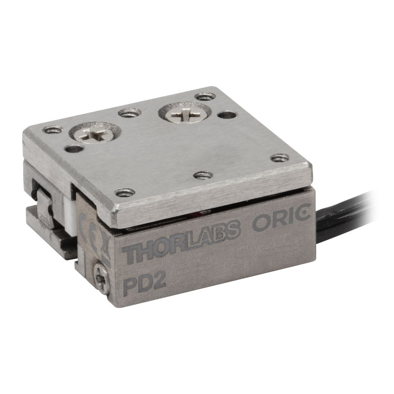
| Product Family | ORIC® PDXZ1 Closed-Loop 4.5 mm Vertical Stage |
ORIC® PD2 Open-Loop 5 mm Stage |
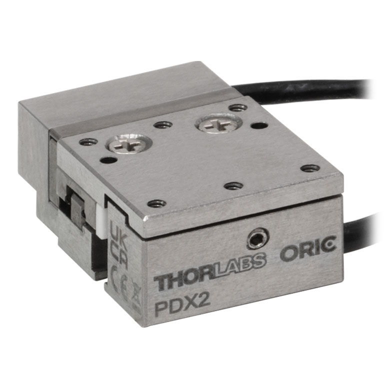
ORIC® PDX2 Closed-Loop 5 mm Stage |
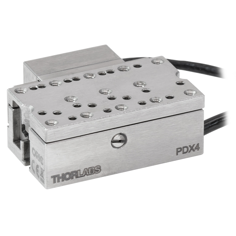
ORIC® PDX4 Closed-Loop 12 mm Stage |
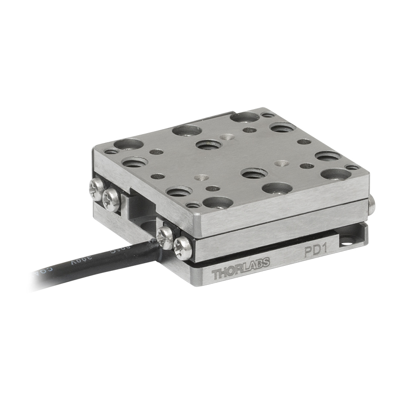
ORIC® PD1 Open-Loop 20 mm Stage |
ORIC® PD1D Open-Loop 20 mm Monolithic XY Stage |
| Click Photo to Enlarge |
 |
 |
 |
 |
 |
 |
| Travel | 4.5 mm | 5 mm | 12 mm | 20 mm | ||
| Speed | 1 mm/s (Typ.)a | 10 mm/s (Typ. Max)b | 8 mm/s (Typ.)c | 15 mm/s (Typ.)a,c | 3 mm/s (Typ. Max)d | |
| Drive Type | Piezoelectric Inertia Drive | |||||
| Possible Axis Configurations | Z | X, XY, XYZ | XY, XYZ | |||
| Mounting Surface Size |
45.0 mm x 42.0 mm | 13.0 mm x 13.0 mm | 13.0 mm x 23.0 mm | 30.0 mm x 30.0 mm | ||
| Additional Details | ||||||
| Piezoelectric Stages | ||||||
|---|---|---|---|---|---|---|
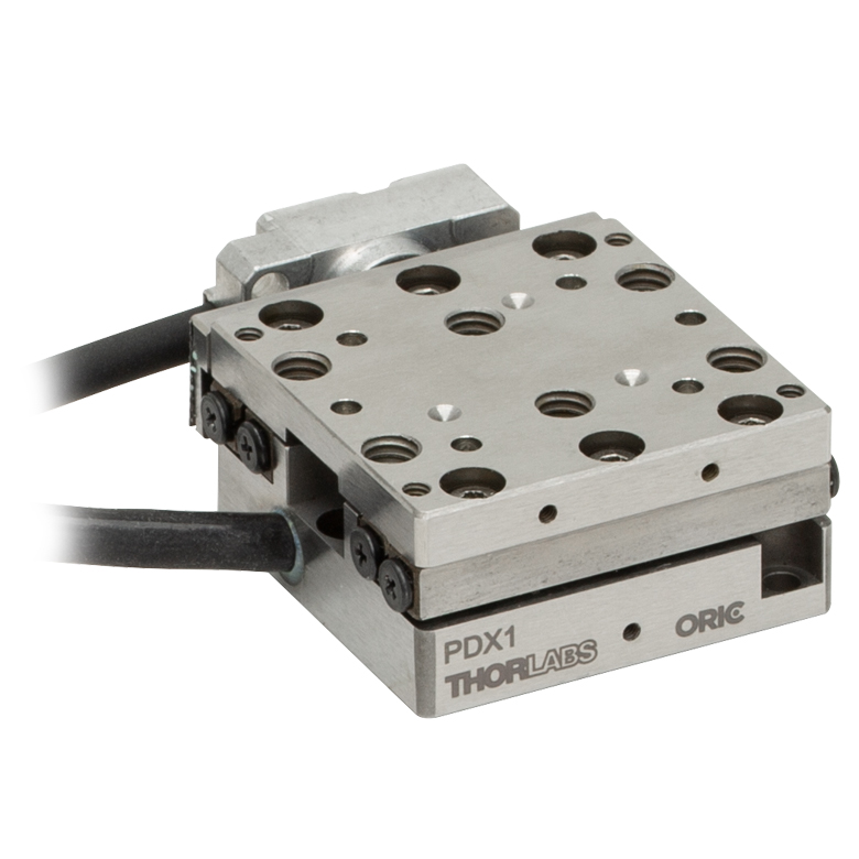
| Product Family | ORIC® PDX1 Closed-Loop 20 mm Stage |
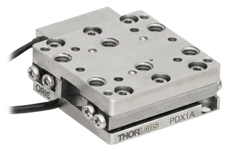
ORIC® PDX1A Closed-Loop 20 mm Stage Low-Profile |
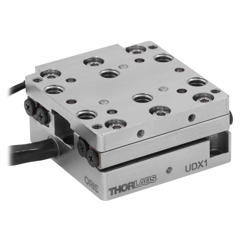
ORIC® UDX1 Ultrasonic Closed-Loop 20 mm Stage |
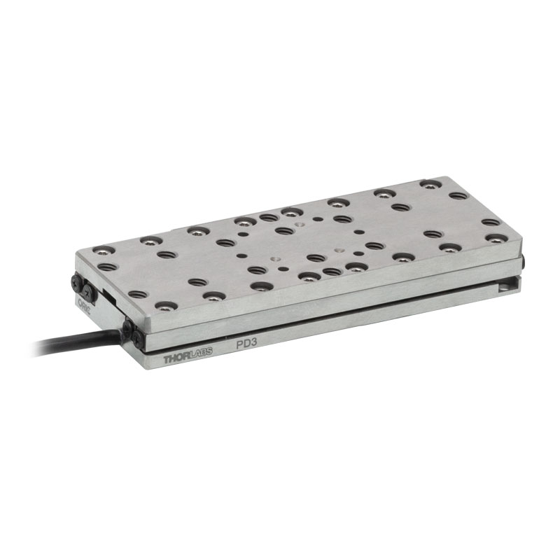
ORIC® PD3 Open-Loop 50 mm Stage |
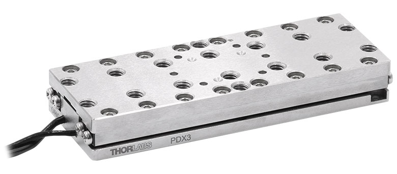
ORIC® PDX3 Closed-Loop 50 mm Stage |
|
| Click Photo to Enlarge |
 |
 |
 |
 |
 |
|
| Travel | 20 mm | 50 mm | ||||
| Speed | 20 mm/s (Typ. Max)a | 10 mm/s (Typ.)b | 100 mm/s (Typ. Max)c | 10 mm/sd | 10 mm/s (Typ. Max)b | |
| Drive Type | Piezoelectric Inertia Drive | Ultrasonic Piezoelectric Drive | Piezoelectric Inertia Drive | |||
| Possible Axis Configurations | X, XY, XYZ | |||||
| Mounting Surface Size |
30.0 mm x 30.0 mm | 80.0 mm x 30.0 mm | ||||
| Additional Details | ||||||
| Piezoelectric Stages | |||||||
|---|---|---|---|---|---|---|---|
| Product Family | Nanoflex™ 20 µm Stage with 5 mm Actuator |
Nanoflex™ 25 µm Stage with 1.5 mm Actuator |
Compact Modular XRN25X 25 mm Stage |
Modular XR25X 25 mm Stage |
Elliptec® 28 mm Stage | Elliptec® 60 mm Stage | LPS710E 1.1 mm Vertical Stage |
| Click Photo to Enlarge |
 |
 |
 |
 |
 |
 |
 |
| Travel | 20 µm + 5 mm Manual | 25 µm + 1.5 mm Manual | 25 mm | 28 mm | 60.0 mm | 1.1 mm | |
| Maximum Velocity | - | ≤3.6 mm/mina | 180 mm/s | 90 mm/s | - | ||
| Drive Type | Piezo with Manual Actuator | Piezoelectric Inertia Drive | Resonant Piezoelectric Motor | Amplified Piezo | |||
| Possible Axis Configurations | X, XY, XYZ | X, XY, YZ, XZ, XYZ | X | Z | |||
| Mounting Surface Size | 75 mm x 75 mm | 30 mm x 30 mm | 85.0 mm x 50.7 mm | 110.0 mm x 75.7 mm | 15 mm x 15 mm | 21 mm x 21 mm | |
| Additional Details | |||||||
Stepper Motor Stages
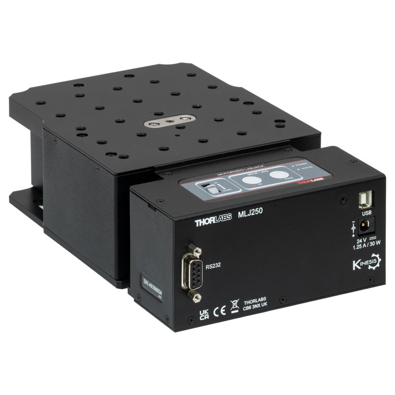
These translation stages feature removable or integrated stepper motors and long travel ranges up to 300 mm. Many of these stages either have integrated multi-axis capability (PLSXY) or can be assembled into multi-axis configurations (PLSX, LNR Series, NRT Series, and LTS Series stages). The MLJ150 stage also offers high load capacity vertical translation.
| Stepper Motor Stages | |||||
|---|---|---|---|---|---|
| Product Family | PLSX with and without PLST(/M) Top Plate 1" Stage |
PLSXY with and without PLST(/M) Top Plate 1" Stage |
LNR Series 25 mm Stage |
LNR Series 50 mm Stage |
|
| Click Photo to Enlarge |
 |
 |
 |
 |
|
| Travel | 1" | 25 mm | 50 mm | ||
| Maximum Velocity | 7.0 mm/s | 2.0 mm/s | 50 mm/s | ||
| Possible Axis Configurations |
X, XY | X, XY, XYZ | X, XY, XYZ | ||
| Mounting Surface Size |
3" x 3" | 60 mm x 60 mm | 100 mm x 100 mm | ||
| Additional Details | |||||
| Stepper Motor Stages | |||||||
|---|---|---|---|---|---|---|---|
| Product Family | NRT Series 100 mm Stage |
NRT Series 150 mm Stage |
LTS Series 150 mm Stage |
LTS Series 300 mm Stage |
LTS Series 450 mm Stage |
MLJ250 50 mm Vertical Stage |
|
| Click Photo to Enlarge |
 |
 |
 |
 |
 |
 |
|
| Travel | 100 mm | 150 mm | 150 mm | 300 mm | 450 mm | 50 mm | |
| Maximum Velocity | 30 mm/s | 50 mm/s | 3.0 mm/s | ||||
| Possible Axis Configurations |
X, XY, XYZ | X, XY, XYZ | X, XY | Z | |||
| Mounting Surface Size |
84 mm x 84 mm | 100 mm x 90 mm | 148 mm x 131 mm | ||||
| Additional Details | |||||||
DC Servo Motor Stages
Thorlabs offers linear translation stages with removable or integrated DC servo motors. These stages feature low profiles and many can be assembled in multi-axis configurations.
| DC Servo Motor Stages | ||||
|---|---|---|---|---|
| Product Family | MT Series 12 mm Stages |
PT Series 25 mm Stages |
MTS Series 25 mm Stage |
MTS Series 50 mm Stage |
| Click Photo to Enlarge |
 |
 |
 |
 |
| Travel | 12 mm | 25 mm | 25 mm | 50 mm |
| Maximum Velocity | 2.6 mm/s | 2.4 mm/s | ||
| Possible Axis Configurations | X, XY, XYZ | X, XY, XYZ | ||
| Mounting Surface Size |
61 mm x 61 mm | 101.6 mm x 76.2 mm | 43 mm x 43 mm | |
| Additional Details | ||||
| DC Servo Motor Stages | ||||
|---|---|---|---|---|
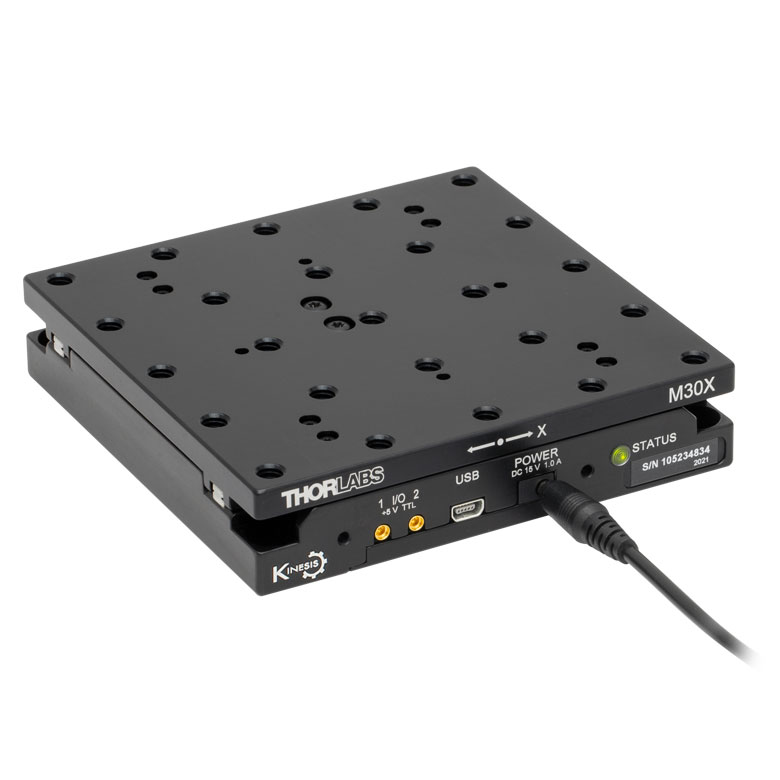
| Product Family | M30 Series 30 mm Stage |
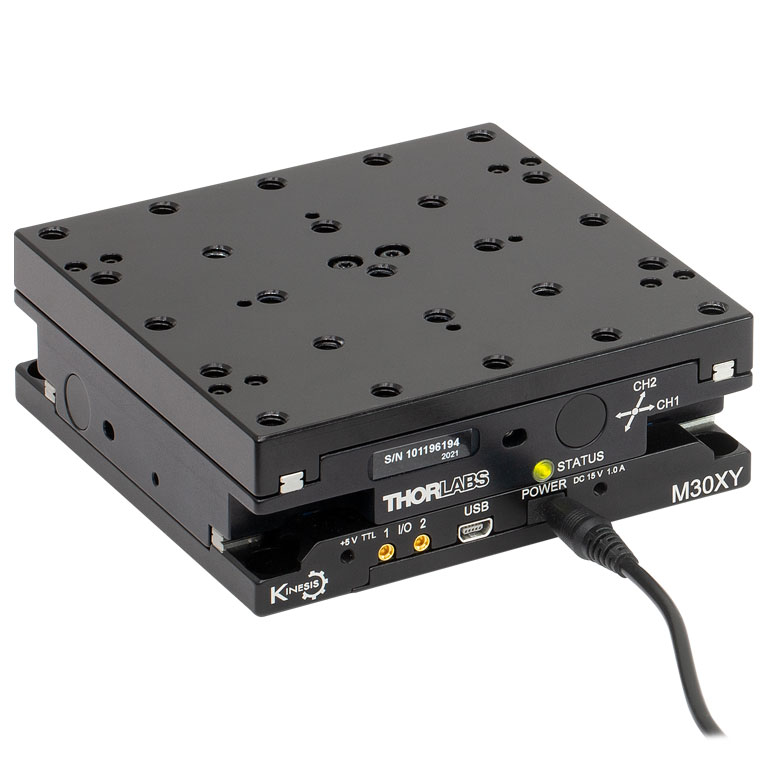
M30 Series 30 mm Monolithic XY Stage |
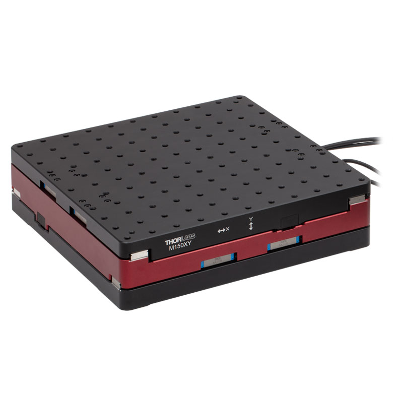
M150 Series 150 mm XY Stage |
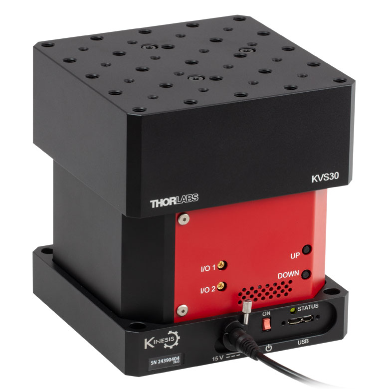
KVS30 30 mm Vertical Stage |
| Click Photo to Enlarge |
 |
 |
 |
 |
| Travel | 30 mm | 150 mm | 30 mm | |
| Maximum Velocity | 2.4 mm/s | X-Axis: 170 mm/s Y-Axis: 230 mm/s |
8.0 mm/s | |
| Possible Axis Configurations | X, Z | XY, XZ | XY | Z |
| Mounting Surface Size |
115 mm x 115 mm | 272.4 mm x 272.4 mm | 116.2 mm x 116.2 mm | |
| Additional Details | ||||
Direct Drive Stages
These low-profile stages feature integrated brushless DC servo motors for high speed translation with zero backlash. When no power is applied, the platforms of these stages have very little inertia and are virtually free running. Hence these stages may not be suitable for applications where the stage's platform needs to remain in a set position when the power is off. We do not recommend mounting these stages vertically.
| Direct Drive Stages | |||||
|---|---|---|---|---|---|
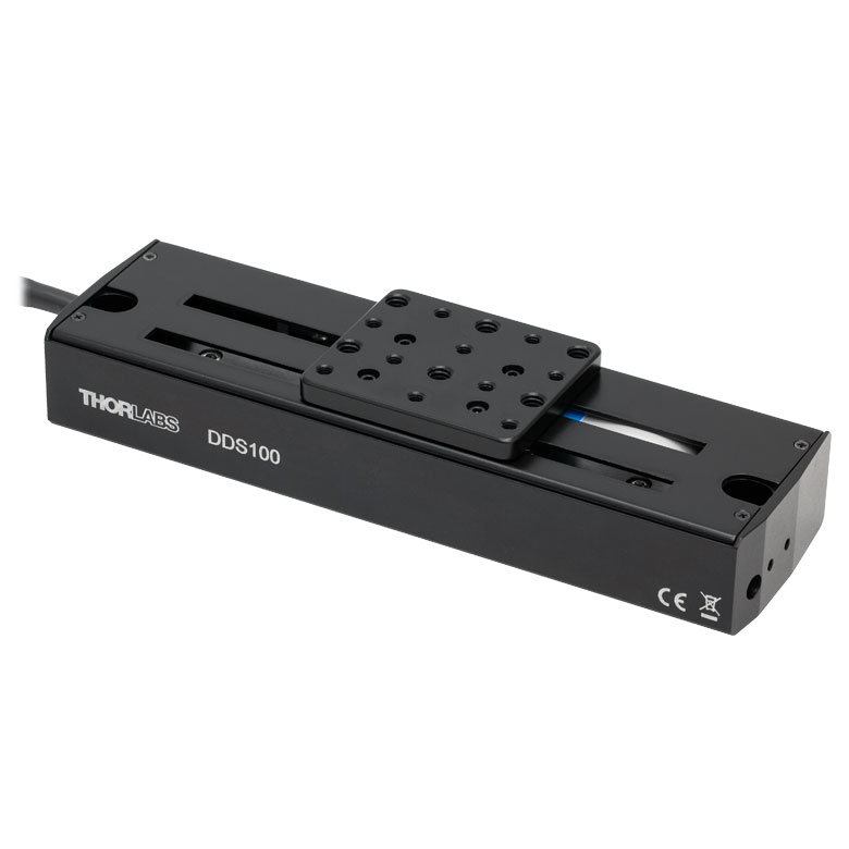
| Product Family | DDS Series 50 mm Stage |
DDS Series 100 mm Stage |
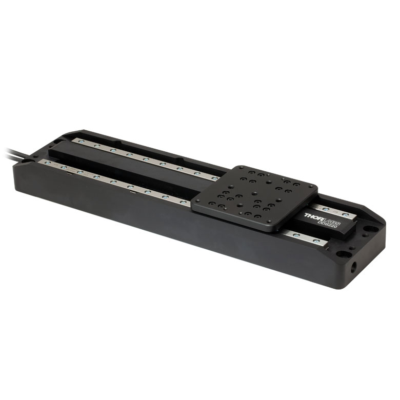
DDS Series 220 mm Stage |
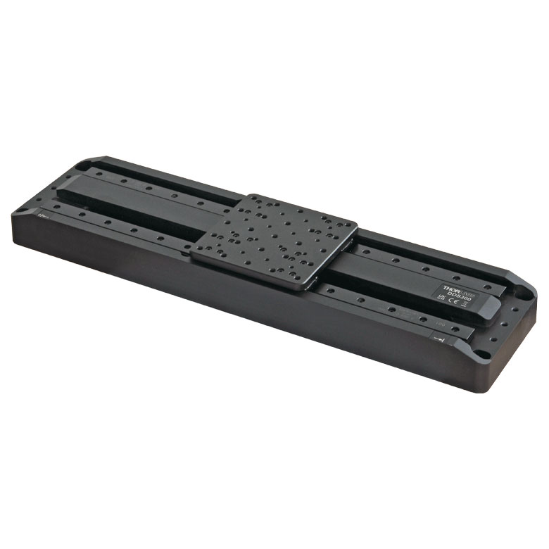
DDS Series 300 mm Stage |
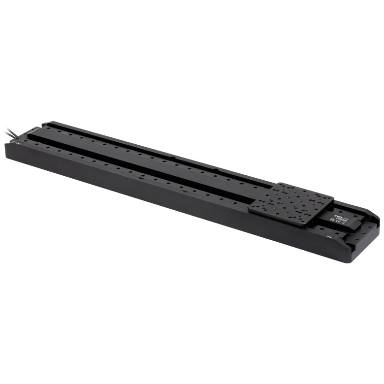
DDS Series 600 mm Stage |
| Click Photo to Enlarge |
 |
 |
 |
 |
 |
| Travel | 50 mm | 100 mm | 220 mm | 300 mm | 600 mm |
| Maximum Velocity | 500 mm/s | 300 mm/s | 400 mm/s | 400 mm/s | |
| Possible Axis Configurations | X, XY | X, XY | X | X | |
| Mounting Surface Size | 60 mm x 52 mm | 88 mm x 88 mm | 120 mm x 120 mm | ||
| Additional Details | |||||
 Low-Profile Motorized Translation Stage")
 Zoom
Zoom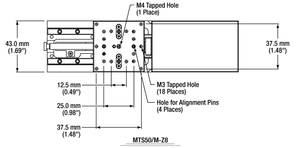
Click to Enlarge
Figure G1.2 Schematic of Metric Version

Click to Enlarge
Figure G1.1 Schematic of Imperial Version
- Built-In 50 mm (1.97") DC Servo Actuator
- Includes One 8-32 (M4 x 0.7) and Eighteen 4-40 (M3 x 0.5) Tapped Holes
- Bundles Available with KDC101 Controller and KPS101* Power Supply
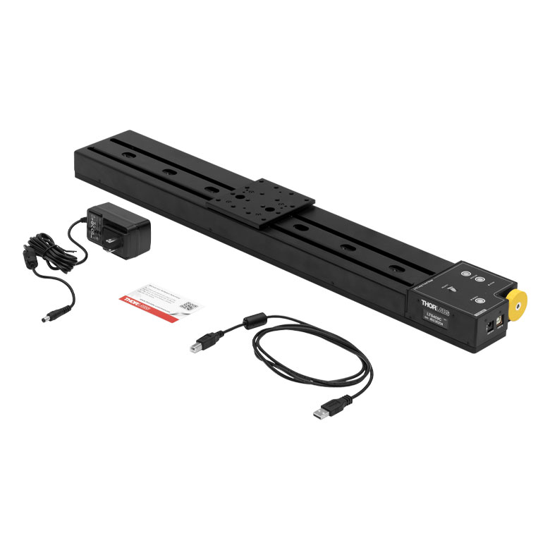
Thorlabs' MTS50(/M)-Z8 Motorized Translation Stage provides linear motion in one dimension. One centered 8-32 (M4 x 0.7) tapped hole and eighteen 4-40 (M3 x 0.5) tapped holes allow small optomechanics to be directly mounted to the moving platform. Based upon a dual set of linear rails with continuously recirculating ball bearings, the translation mechanism provides smooth, low-friction movement.
The stage requires our KDC101 K-Cube® DC Servo Motor Controller and Power Supply (each sold separately), which are described in more detail below. For convenience, we also offer a stage, KDC101 Motor controller, and KPS101* power supply in a bundle at a significant savings over purchasing these items individually. The power supply you receive will be compatible with outlets in your region. Please contact Tech Sales prior to ordering if you require a different plug.
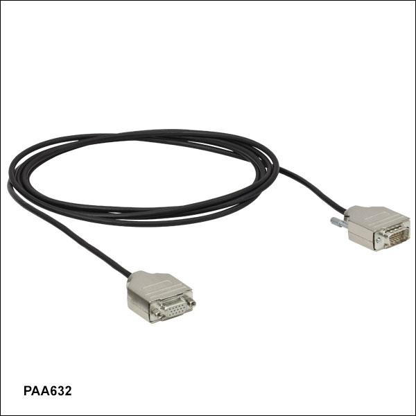
The motor cable that is built into the stage is 0.5 m (1.64 ft) long. If more length is required for your application, we recommend our PAA632 Extension Cable, which provides an additional 2.5 m (8.20 ft).
*This previous-generation item is not available for individual purchase. If a replacement is needed, the KPS201 Power Supply can be used.

 Zoom
Zoom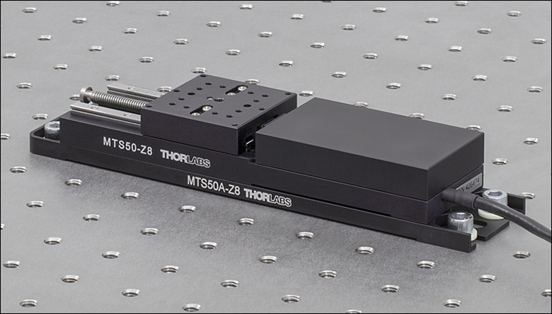 Click to Enlarge
Figure G2.1 MTS50-Z8 Stage on an Optical Table with MTS50A-Z8 Base Plate
- Mount an MTS50(/M)-Z8 Stage to an Optical Table or Breadboard
- Contains Four 1/4" (M6) Counterbored Slots for Imperial and Metric Compatibility
- Includes All Necessary Mounting Hardware and Alignment Pins for Parallelism
The MTS50A-Z8 Base Plate contains four 1/4" (M6) counterbored slots that allow an attached MTS50(/M)-Z8 to be positioned on a breadboard, as shown in Figure G2.1. The bottom of the translation stage is connected to the base plate using four 4-40 or M3 x 0.5 cap screws. Two alignment pins ensure that the translation axis is parallel to the length of the plate.
 and 8-32 (M4 x 0.7) Tapped Holes")
 Zoom
Zoom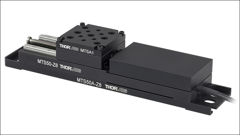 Click to Enlarge
Figure G3.1 MTSA1 Adapter Plate Attached to MTS50-Z8 Stage
Click to Enlarge
Figure G3.1 MTSA1 Adapter Plate Attached to MTS50-Z8 Stage- Mount Standard Optical Accessories
- Features Seven 1/4"-20 (M6 x 1.0) and Six 8-32 (M4 x 0.7) Mounting Holes
- Increases Height of Moving World by 7.5 mm
- Includes All Necessary Mounting Hardware
The MTSA1(/M) adapter plate is secured to the top platform of the MTS50(/M)-Z8 stage using 4-40 screws (included) in each corner. It has an array of seven 1/4"-20 (M6 x 1.0) and six 8-32 (M4 x 0.7) mounting holes to offer increased mounting options when used with general-purpose accessories and components. The working height of the stage with an adapter plate is increased by 7.5 mm. The plate is finished in a black, low reflective anodized coating.

 Zoom
Zoom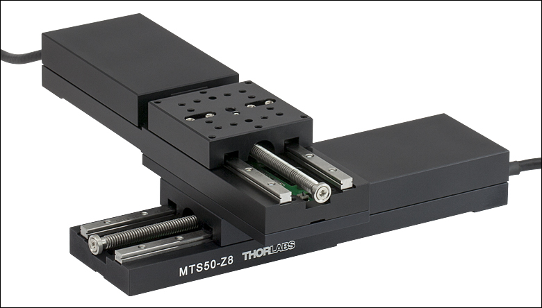 Click to Enlarge
Figure G4.1 Two MTS50-Z8 Stages in XY Configuration with MTS50B-Z8 Adapter
| Max Load on Top Stage | |
|---|---|
| Top Stage | Max Loada |
| MTS100(/M)-Z8 | 2.2 lbs (1 kg) |
| MTS50(/M)-Z8 | 3.7 lbs (1.7 kg) |
| MTS25(/M)-Z8 | 10 lbs (4.5 kg) |
- Stack Two MTS50(/M)-Z8 Stages in an XY Configuration
- Includes All Necessary Mounting Hardware and Alignment Pins for Orthogonality
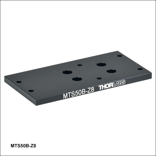
The MTS50B-Z8 XY Adapter Plate is designed to orient two MTS50(/M)-Z8 stages orthogonally in the XY plane, as shown in Figure G4.1. Note that due to stage torque over the travel range, the max load on the top stage is reduced to 3.7 lbs lbs (1.7 kg). Staying at/below this load on the top (Y-axis) stage ensures that the stages meet performance specifications. This plate may also be used to mount an MTS50(/M)-Z8 stage on top of a 25 mm (0.98") MTS25(/M)-Z8 stage or 100 mm (3.94") MTS100(/M)-Z8 stage.
To begin the assembly process, fasten the plate to the top of the lower stage using four of the provided 4-40 or M3 x 0.5 cap screws. Then insert the provided alignment pins. To complete the assembly, use the remaining 4-40 or M3 x 0.5 cap screws to fasten the plate to the bottom of the upper stage.
Thorlabs' MTS25(/M)-Z8 stage or MTS100(/M)-Z8 stage can also be mounted on top of an MTS50(/M)-Z8 stage in an XY configuration using the MTS25B-Z8 or MTS100B-Z8 adapter plates, respectively. Note that when using an MTS100(/M)-Z8 stage on top, the max load on the top stage is reduced to 2.2 lbs (1.0 kg) due to stage torque over the travel range.

 Zoom
Zoom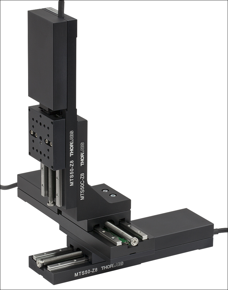
Click to Enlarge
Figure G5.1 Three MTS50-Z8 Stages in XYZ Configuration with MTS50B-Z8 Adapter and MTS50C-Z8 Right-Angle Bracket
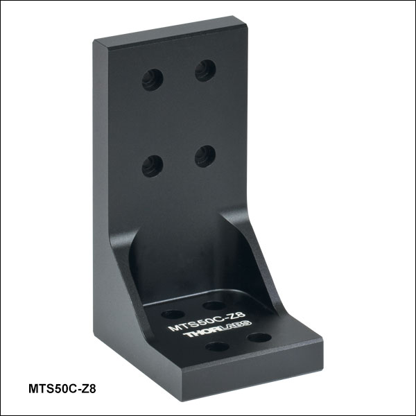
- Vertically Mount an MTS50(/M)-Z8 Translation Stage
- Designed for XZ or XYZ Configurations
- Includes All Necessary Mounting Hardware and Alignment Pins for Orthogonality
The MTS50C-Z8 Right-Angle Bracket orients an MTS50(/M)-Z8 stage along the vertical axis. It is needed when configuring multiple MTS50(/M)-Z8 stages into XZ or XYZ arrangements. This bracket may also be used to mount a 25 mm (0.98") MTS25-Z8 stage on top of an MTS50(/M)-Z8 stage.
To create the XYZ configuration shown in Figure G5.1, first create an XY configuration using the MTS50B-Z8 XY Adapter Plate shown above. Then insert two of the provided alignment pins into the upper stage of the XY configuration. Next, fasten the bracket to the top of the upper stage using four of the provided 4-40 or M3 x 0.5 cap screws. After that, insert the two remaining alignment pins into the vertical mounting surface. Finally, attach the bracket to the upper stage with the remaining cap screws.

 Zoom
Zoom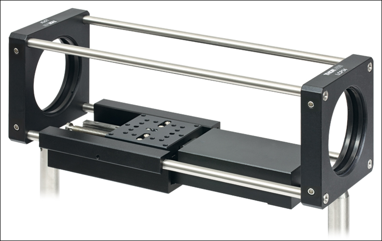 Click to Enlarge
Figure G6.1 MTS50-Z8 in 60 mm Cage System Using MTS50CSA Adapter
Click to Enlarge
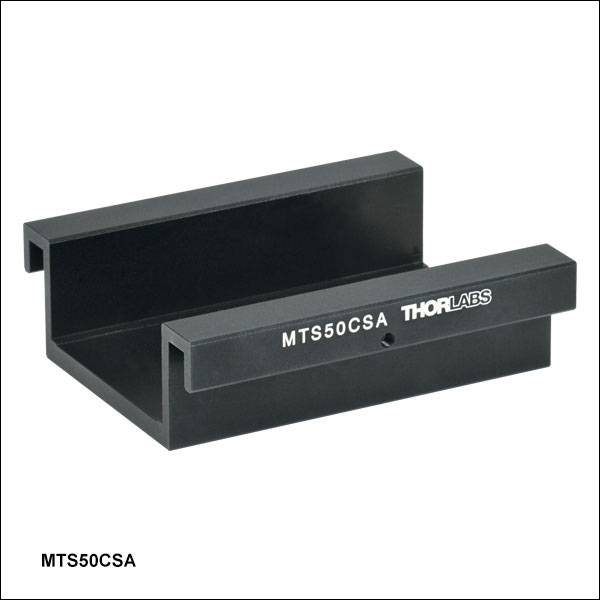
Figure G6.1 MTS50-Z8 in 60 mm Cage System Using MTS50CSA Adapter- Mount an MTS50(/M)-Z8 Translation Stage in a 60 mm Cage System
- Installation Does Not Require Cage System to be Disassembled
- Includes All Necessary Mounting Hardware and Alignment Pins for Parallelism
The MTS50CSA Adapter Plate orients an MTS50(/M)-Z8 stage parallel to the optical axis in a 60 mm cage system. This allows optics within the cage to be translated over a 50 mm (1.97") range. The cage segment need only be long enough to accommodate the 6.33" (160.8 mm) length of the MTS50(/M)-Z8 stage; no additional length is required. An example of the MTS50CSA in use is shown in Figure G6.1.
To install, insert the two provided alignment pins into the bottom of the stage. Then fasten the adapter to the stage using the four provided 4-40 or M3 cap screws. At this point, the assembly can be inserted through the cage rods in an existing setup. Finally, tighten the two nylon-tipped setscrews against the rods.

 Zoom
Zoom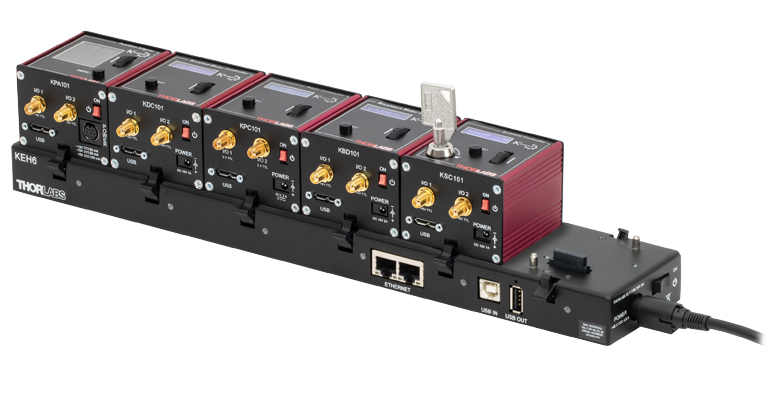 Click to Enlarge
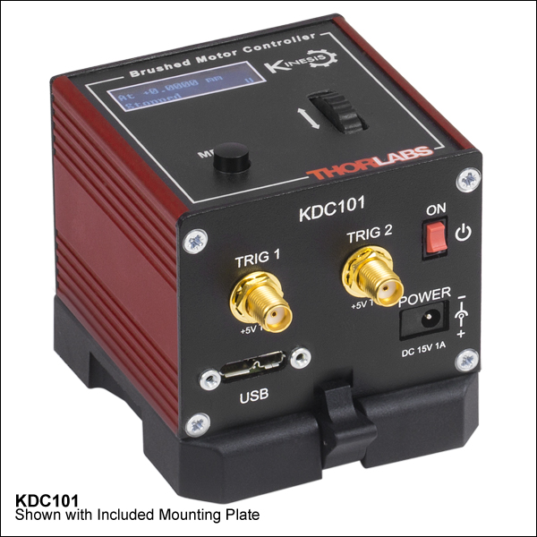
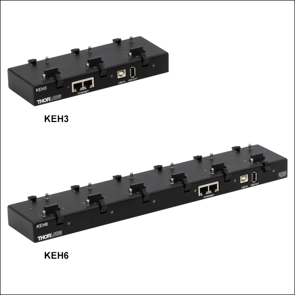
Figure 779A KEH6 Ethernet and USB Controller Hub (Sold Separately) with Installed K-Cube® Modules
- Front Panel Velocity Wheel and Digital Display for Controlling Motorized Stages or Actuators
- Two Bidirectional Trigger Ports to Read or Control External Equipment
- Interfaces with Computer Using Included USB Cable
- Fully Compatible with Kinesis and XA Software Packages
- Compact Footprint: 60.0 mm x 60.0 mm x 49.2 mm (2.42" x 2.42" x 1.94")
- Power Supply Not Included (See Below)
Thorlabs' KDC101 K-Cube® Brushed DC Motor Controller provides local and computerized control of a single motor axis. It features a top-mounted control panel with a velocity wheel that supports four-speed bidirectional control with forward and reverse jogging as well as position presets. A backlit digital display is also included that can have the backlit dimmed or turned off using the top-panel menu options. The front of the unit contains two bidirectional trigger ports that can be used to read a 5 V external logic signal or output a 5 V logic signal to control external equipment. Each port can be independently configured.
The KDC101 is fully compatible with our Kinesis and XA software packages, but not all motion control devices are supported by XA at this time. A full list of devices supported by XA can be found here. Please see the Kinesis and XA Software tab for more information.
Please note that this controller does not ship with a power supply. Compatible power supplies are listed below. Additional information can be found on the main KDC101 DC Servo Motor Controller page.

 Zoom
Zoom
Click for Details
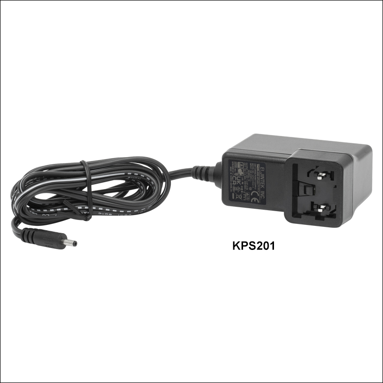
Figure 780B Each KPS201 power supply includes one region-specific adapter, which can be selected upon checkout.
Click to Enlarge
Figure 780A The KPS201 Power Supply Unit
- Individual Power Supply
- KPS201: For K-Cubes® or T-Cubes™ with 3.5 mm Jacks
- Ethernet and USB Controller Hubs Provide Power and Communications
- KEH3: For Up to Three K-Cubes or T-Cubes
- KEH6: For Up to Six K-Cubes or T-Cubes
The KPS201 power supply outputs +15 VDC at up to 2.66 A and can power a single K-Cube or T-Cube with a 3.5 mm jack. It plugs into a standard wall outlet.
The KEH3 and KEH6 Controller Hubs contain a fully compliant USB 2.0 hub circuit and provide all communications and power distribution for up to three (Item # KEH3) or six (Item # KEH6) K-Cubes or T-Cubes (KAP101 or KAP102 adapters are needed for T-Cubes), using only a single power connection. Additionally, the hubs have two Ethernet connection ports. The second Ethernet port or USB OUT port can be connected to the input on another Controller Hub to allow multiple Controller Hub connections while still only requiring a single Ethernet or USB cable from the host PC. The hubs draw a maximum current of 4.6 A; please verify that the cubes being used do not require a total current of more than 4.6 A.
For more information on the controller hubs, see the full web presentation.

 Zoom
ZoomThe PAA632 Extension Cable provides an additional 2.5 m (8.20 ft) of cable length for the 15-pin D-type connectors used throughout our motorized actuator selection. The male end connects to the controller, while the female end connects to the motor.