Linear Translation Stages: 50 mm (1.97") Travel, Motorized, Crossed-Roller Bearings
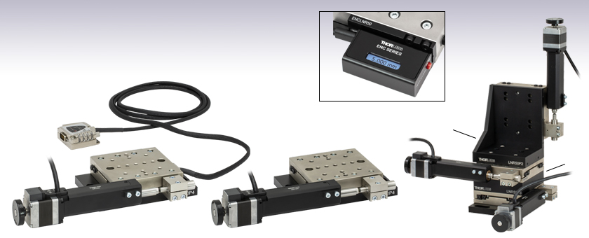
- 50 mm (1.97") of Travel
- Horizontal Load Capacity of 48 kg (105 lbs)
- Rigid, Durable, Thermally Matched Steel Construction
- Available With or Without an Optical Encoder
LNR502E
Optically Encoded Version
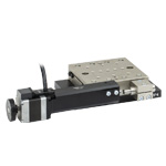
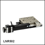
LNR502
Standard Version
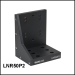
LNR50P2
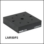
LNR50P3
Mounting Adapters Used to
Create an XYZ TravelMax™
Stage Configuration
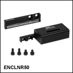
ENCLNR50
Stage Position Encoder
Attached to LNR502 Stage
(Each Sold Separately)

Please Wait
| Key Specificationsa | ||
|---|---|---|
| Item # | LNR502(/M) | LNR502E(/M) |
| Travel Range | 50 mm (1.97") | |
| Velocity (Max) | 50 mm/s | |
| Min Achievable Incremental Movementb,c | 0.05 µm | |
| Min Repeatable Incremental Movementb,c | 1 µm | 0.1 µm |
| Bidirectional Repeatabilityd | ±3.9 µm | ±0.75 µm |
| Backlashe | <6 µm | |
| Horizontal Load Capacity (Max) | 48 kg (105 lbs) | |
| Vertical Load Capacity (Max) | 10 kg (22 lbs) | |
| Included Actuator | DRV250 Stepper Motor | |
| Cable Length | 0.5 m (1.64 ft) | |
| Recommended Controller | APT™ Stepper Motor Controllers | |
| Motorized Linear Translation Stages | |
|---|---|
| 12 mm | Standard |
| 25 mm | Compact |
| Standard | |
| TravelMax™ | |
| 50 mm | Compact |
| Direct-Drive Servo | |
| TravelMax | |
| Long Travel: 100 mm to 300 mm | |
Features
- 50 mm (1.97") Travel Range
- Rugged, Thermally Matched Steel Construction with Heavy-Duty Crossed-Roller Bearings
- Moving Platform has Thirteen 1/4"-20 (M6) Taps
- Trapezoidal Lead Screw Stepper Motor for Cleaner, More Wear-Resistant Operation
- Adapters Available for Breadboard Mounting and XY, XZ, and XYZ Arrangements
- Offered With or Without a Linear Optical Encoder
Thorlabs' 50 mm Travel Motorized Translation Stages are designed for applications that require stability, long travel, and high load capacity. Horizontal and vertical loads up to 48 kg (105 lbs) and 10 kg (22 lbs) are supported, respectively. Each stage's moving platform is equipped with thirteen 1/4"-20 (M6) taps for compatibility with standard optomechanics.
The moving platform contains holes for alignment pins that ensure orthogonality when the stage is stacked with other stages or connected to our accessories. The rigidity of the thermally matched, all-steel construction, along with the heavy-duty crossed-roller bearings, provides precision motion and long life, even in less-than-ideal conditions.
The LNR502(/M) non-encoded translation stage offers a minimum repeatable incremental movement of 1 µm and ±3.9 µm of bidirectional repeatability. For even more precise movement, the LNR502E(/M) Encoded Translation Stage combines a linear optical encoder and everything included with the LNR502(/M) stage to achieve a minimum repeatable incremental movement of 0.1 µm and improved bidirectional repeatability of ±0.75 µm.
Separate Encoder Option
The ENCLNR50 Optical Encoder can be mounted to the non-encoded LNR502(/M) translation stages (as well as the LNR502E(/M) encoded stages) and provides positional information in either inches or millimeters to a resolution of 1.0 µm and an accuracy of 10.0 µm.
Mounting Adapters and Stage Combinations
Thorlabs manufactures three adapter plates to maximize the mounting flexibility of these stages. The LNR50P2(/M) Right-Angle Bracket and LNR50P3(/M) Spacer Plate allow for easy configuration of left- or right-handed XY, XZ, or XYZ systems. A base plate, which provides sufficient clearance between the stage and the work surface for operation of the DRV250 stepper motor actuator, is included with each translation stage.
Included Actuator
The translation stages sold here include a DRV250 stepper motor actuator. For applications requiring fine positioning, the removable static pin that provides a stop for the stage's motor drive can be replaced by a piezo drive. Combining the standard stepper motor actuator with a piezo drive allows for both long travel and fine adjustment. Both open-loop and closed-loop piezo drives are available with 20 µm to 100 µm of travel and resolution as low as 5 nm.
Controller Options
For stepper motors such as the one included with the LNR502(/M) and LNR502E(/M) translation stages, Thorlabs recommends using a BSC201, BSC202, or BSC203 Stepper Motor Controller. Any of these controllers can be purchased separately.
Thorlabs also manufactures the MTS50-Z8 Motorized Translation Stage, which features a built-in actuator and reduced overall package size.
Motor Specifications
| Parameter | Value |
|---|---|
| Motor Type | DRV250 2-Phase Stepper Motor |
| Cable Length | 0.5 m (1.64 ft) |
| Maximum Pushing Forcea | 180 N |
| Microsteps per Revolution | 409 600 |
| Leadscrew Pitch | 1.0 mm |
| Limit Switches | Hall Effect |
| Maximum Speed | 50 mm/s |
| Full Step Angle | 1.8° |
| Rated Phase Current | 0.85 A |
| Phase Resistance | 3.6 Ω |
| Phase Inductance | 4.6 mH |
| Holding Torque | 0.2 N•m |
| Rotor Inertia | 24 x 10-7 kg•m2 |
Stage Specifications
| Item # | LNR502(/M) | LNR502E(/M) |
|---|---|---|
| Translation | ||
| Travel Range | 50 mm (1.97") | |
| Bidirectional Repeatabilitya | ±3.9 µm | ±0.75 µm |
| Unidirectional Repeatability | ±1.6 µm | ±0.36 µm |
| Backlashb | <6 µm | |
| Min Achievable Incremental Movementc,d | 0.05 µm | |
| Min Repeatable Incremental Movementd,e | 1 µm | 0.1 µm |
| Home Location Accuracy | ±1.0 µm | |
| Motion Parameters | ||
| Velocity (Max) | 50 mm/s | |
| Velocity Stability | ±0.4 mm/s | |
| Acceleration (Max) | 50 mm/s2 | |
| Load Capacity | ||
| Vertical Load | Recommended: ≤10 kg (22 lbs) Max: 10 kg (22 lbs) |
|
| Horizontal Load | Recommended: ≤25 kg (55 lbs) Max: 48 kg (105 lbs) |
|
| Orthogonality | ||
| Pitch | 0.03° (524 µrad) | |
| Yaw | 0.015° (262 µrad) | |
| Bidirectional Accuracy | 35 µm | 6 µm |
| Physical | ||
| Dimensionsf | 10.49" x 5.39" x 2.01" (266.7 mm x 136.8 mm x 51.0 mm) |
|
| Weight | 2.8 kg (6.17 lbs) | 3.1 kg (6.83 lbs) |
Please refer to the descriptions below if you wish to use your own controller with these TravelMax™ motorized translation stages.
DRV250 Stepper Motor Connector Pins

High-Density DE-15 Male Connector
| Pin | Description | Pin | Description |
|---|---|---|---|
| 1 | Limit Grounda | 9 | Ident (for Future Use) |
| 2 | CCW Limit Switch | 10 | +5 V |
| 3 | CW Limit Switch | 11 | Reserved for Future Use |
| 4 | Motor Phase B- | 12 | Reserved for Future Use |
| 5 | Motor Phase B+ | 13 | +5 V |
| 6 | Motor Phase A- | 14 | Reserved for Future Use |
| 7 | Motor Phase A+ | 15 | Ground |
| 8 | Reserved for Future Use | - | - |
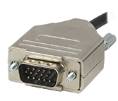
Click to Enlarge
High-Density DE-15 Male Connector
Thorlabs offers two platforms to drive our wide range of motion controllers: our Kinesis® software package or the legacy APT™ (Advanced Positioning Technology) software package. Either package can be used to control devices in the Kinesis family, which covers a wide range of motion controllers ranging from small, low-powered, single-channel drivers (such as the K-Cubes™ and T-Cubes™) to high-power, multi-channel, modular 19" rack nanopositioning systems (the APT Rack System).
The Kinesis Software features .NET controls which can be used by 3rd party developers working in the latest C#, Visual Basic, LabVIEW™, or any .NET compatible languages to create custom applications. Low-level DLL libraries are included for applications not expected to use the .NET framework. A Central Sequence Manager supports integration and synchronization of all Thorlabs motion control hardware.

Kinesis GUI Screen
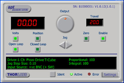
APT GUI Screen
Our legacy APT System Software platform offers ActiveX-based controls which can be used by 3rd party developers working on C#, Visual Basic, LabVIEW™, or any Active-X compatible languages to create custom applications and includes a simulator mode to assist in developing custom applications without requiring hardware.
By providing these common software platforms, Thorlabs has ensured that users can easily mix and match any of the Kinesis and APT controllers in a single application, while only having to learn a single set of software tools. In this way, it is perfectly feasible to combine any of the controllers from single-axis to multi-axis systems and control all from a single, PC-based unified software interface.
The software packages allow two methods of usage: graphical user interface (GUI) utilities for direct interaction with and control of the controllers 'out of the box', and a set of programming interfaces that allow custom-integrated positioning and alignment solutions to be easily programmed in the development language of choice.
A range of video tutorials is available to help explain our APT system software. These tutorials provide an overview of the software and the APT Config utility. Additionally, a tutorial video is available to explain how to select simulator mode within the software, which allows the user to experiment with the software without a controller connected. Please select the APT Tutorials tab above to view these videos.
Software
Kinesis Version 1.14.49
The Kinesis Software Package, which includes a GUI for control of Thorlabs' Kinesis and APT™ system controllers.
Also Available:
- Communications Protocol
The APT video tutorials available here fall into two main groups - one group covers using the supplied APT utilities and the second group covers programming the APT System using a selection of different programming environments.
Disclaimer: The videos below were originally produced in Adobe Flash. Following the discontinuation of Flash after 2020, these tutorials were re-recorded for future use. The Flash Player controls still appear in the bottom of each video, but they are not functional.
Every APT controller is supplied with the utilities APTUser and APTConfig. APTUser provides a quick and easy way of interacting with the APT control hardware using intuitive graphical control panels. APTConfig is an 'off-line' utility that allows various system wide settings to be made such as pre-selecting mechanical stage types and associating them with specific motion controllers.
APT User Utility
The first video below gives an overview of using the APTUser Utility. The OptoDriver single channel controller products can be operated via their front panel controls in the absence of a control PC. The stored settings relating to the operation of these front panel controls can be changed using the APTUser utility. The second video illustrates this process.
APT Config Utility
There are various APT system-wide settings that can be made using the APT Config utility, including setting up a simulated hardware configuration and associating mechanical stages with specific motor drive channels. The first video presents a brief overview of the APT Config application. More details on creating a simulated hardware configuration and making stage associations are present in the next two videos.
APT Programming
The APT Software System is implemented as a collection of ActiveX Controls. ActiveX Controls are language-independant software modules that provide both a graphical user interface and a programming interface. There is an ActiveX Control type for each type of hardware unit, e.g. a Motor ActiveX Control covers operation with any type of APT motor controller (DC or stepper). Many Windows software development environments and languages directly support ActiveX Controls, and, once such a Control is embedded into a custom application, all of the functionality it contains is immediately available to the application for automated operation. The videos below illustrate the basics of using the APT ActiveX Controls with LabVIEW, Visual Basic, and Visual C++. Note that many other languages support ActiveX including LabWindows CVI, C++ Builder, VB.NET, C#.NET, Office VBA, Matlab, HPVEE etc. Although these environments are not covered specifically by the tutorial videos, many of the ideas shown will still be relevant to using these other languages.
Visual Basic
Part 1 illustrates how to get an APT ActiveX Control running within Visual Basic, and Part 2 goes on to show how to program a custom positioning sequence.
LabVIEW
Full Active support is provided by LabVIEW and the series of tutorial videos below illustrate the basic building blocks in creating a custom APT motion control sequence. We start by showing how to call up the Thorlabs-supplied online help during software development. Part 2 illustrates how to create an APT ActiveX Control. ActiveX Controls provide both Methods (i.e. Functions) and Properties (i.e. Value Settings). Parts 3 and 4 show how to create and wire up both the methods and properties exposed by an ActiveX Control. Finally, in Part 5, we pull everything together and show a completed LabVIEW example program that demonstrates a custom move sequence.
Part 1: Accessing Online Help
Part 2: Creating an ActiveX Control
Part 3: Create an ActiveX Method
Part 4: Create an ActiveX Property
Part 5: How to Start an ActiveX Control
The following tutorial videos illustrate alternative ways of creating Method and Property nodes:
Create an ActiveX Method (Alternative)
Create an ActiveX Property (Alternative)
Visual C++
Part 1 illustrates how to get an APT ActiveX Control running within Visual C++, and Part 2 goes on to show how to program a custom positioning sequence.
MATLAB
For assistance when using MATLAB and ActiveX controls with the Thorlabs APT positioners, click here.
To further assist programmers, a guide to programming the APT software in LabVIEW is also available here.
| Posted Comments: | |
Andrey Kuznetsov
(posted 2024-07-11 17:15:10.23) LNR502E CAD STEP file has a model problem, the motor's actuator tip that holds the ball is an open sheet model, instead of a solid body. Please re-export to fix the problem. spolineni
(posted 2024-07-17 04:35:40.0) Thank you for bringing this to our attention. We appreciate your valuable feedback regarding the issue with the CAD STEP file. The suggested modification will be implemented soon, and the corrected files will be made available. Kresten Yvind
(posted 2021-08-09 07:24:18.253) I have some old LN50SE stages with a BSC102 controller (which have been idle for many years) which I have started to use in encoder mode. Unfortunately they tend to freeze up (often) and then get very warm. Cycling the power on the controller is needed. Any solution to this?
Is it most likely the stages or controller and will new parts be compatible with the older versions? cwright
(posted 2021-08-09 09:33:08.0) Response from Charles at Thorlabs: Thank you for your query. This is most likely due to some incorrect setting, such as the encoder constant constant or selected stage. We will reach out to you to discuss which software is being used and how we can narrow down the source of the issue. Fedor Talantov
(posted 2021-06-15 19:48:14.517) Does the Horizontal and vertical load capacities apply for the stage being hung upside down? i.e. if a load is suspended from it, rather than placed on top of it? cwright
(posted 2021-06-21 08:08:56.0) Response from Charles at Thorlabs: Unfortunately, we have not tested its load capacity in this orientation. With that being said, the vertical load capacity when mounted upside down should be lower than the spec for the upright configuration. The limiting factor is the spring force. When used horizontally, since the bearings are symmetrical and so there is no specification on the bearings for which way is ‘up’, the load capacity should be the same for the conventional orientation vs upside down with a hanging weight. CHEOL HONG MIN
(posted 2021-01-21 00:17:33.41) Can APT user (APT driver) program or Micro-manager be installed with window 2000 OS?
I'd like to use the LNR502 with win 2000 OS, because of the old school microscope operating application. cwright
(posted 2021-01-21 10:12:21.0) Response from Charles at Thorlabs: Thank you for your query. Unfortunately APT was not designed for Windows 2000 OS. I can see from Micromanager's website that they also do not support Windows 2000. You should still be able to communicate with these stages using serial commands listed in the APT communications protocol: https://www.thorlabs.com/Software/Motion%20Control/APT_Communications_Protocol.pdf wenzel.jakob
(posted 2017-12-08 12:56:50.187) Can rigid stands (e.g. MP100) be mounted on top of the TravelMax translation stages? bwood
(posted 2017-12-13 11:15:42.0) Response from Ben at Thorlabs: Thank you for your feedback. The counterbored slots (appropriate for both 2" and 50mm hole spacing) of the MP100 match with four of the holes on the LNR50. Therefore I am pleased to say you can mount a rigid stand on an LNR50. rayotte
(posted 2017-08-25 11:11:50.04) We have been using the LNR50S for several years. It is beginning to squeal now. Is there a recommended or suggested lubrication and application method available? Thanks. bwood
(posted 2017-09-05 10:27:26.0) Response from Ben at Thorlabs: Thank you for your feedback. There are some ways to lubricate the LNR and attached motor. I will be in direct contact with you to identify the cause of the noise, and the appropriate responce. Sdm314
(posted 2017-01-19 11:09:31.643) Is there a minumum velocity for these stages? We are looking for a stage that can reliably move at speeds of 5-100 um/s. bwood
(posted 2017-01-20 04:10:49.0) Response from Ben at Thorlabs: The theoretical minimum velocity is that which can be commanded by our motion control software, that velocity range is achievable. However, at low velocities the motion of any 2 -phase stepper motor will become unstable. As you reduce the velocity of the stage, the movement may seem to microscopically ‘stop-start’ depending on the application’s requirements. This is due to the time between motor phases increasing to produce this ultra-low velocity which consequently leads to the motor stalling if there are torque hotspots, where say the pitch of the leadscrew is not perfect. This will vary between each model as at this slow speed any irregularities in the stage are emphasised. This would also be heavily dependent upon the load employed. ludoangot
(posted 2016-11-17 09:29:32.267) Ben, thank you. You propose the DDSM50 which I had also considered but from its characteristics (direct drive with no inertia) I understood it is not suitable for z-axis translation (I specified a 600g load on the z-axis). I may be mistaken. How to set up / control the DDSM50 for z-axis translation? bwood
(posted 2016-11-17 04:23:23.0) Response from Ben at Thorlabs: Yes, you are correct, direct drive stages are not recommended for z-axis translation. Apologies if my comment caused any confusion. The LNR50S is probably the best option for the specifications you gave, however if you would like to further discuss your requirements it may be more convient if you email me at techsupport.uk@thorlabs.com ludoangot
(posted 2016-11-10 17:20:30.033) The LNR50S fits my requirements in terms of velocity, what absolute position accuracy can I expect from this non-encoded version and why isn't this accuracy not specified (it may be because it can't be guaranteed?)? Also, I don't need 50mm travel, 12~20mm is ample, but your other travelMax (LNR25ZFS) has a velocity of only 2mm/s. In the hope of finding a less expensive solution, do you offer a 12~20mm travel motorized stage with at least a 10mm/s velocity and better than 5um position accuracy (load would be about 600g, in the z-axis)? bwood
(posted 2016-11-11 05:58:22.0) Response from Ben at Thorlabs:Thank you for your question. We specify the absolute on-axis accuracy for the LNR50S as 10µm. From the specifications you have given, I think another option you may want to consider is the DDSM50. This stage offers up to 500 mm/s velocities, ±5µm accuracy and has a 0.9kg load capacity. It can be found on our website here: https://www.thorlabs.hk/newgrouppage9.cfm?objectgroup_id=8535 christopher.jones
(posted 2016-05-06 15:51:36.013) Hello. I am interested in the LNR50 series, esp. LNR50SE/M. Do you stock an adapter plate (or combination) to mount these stages onto your X95 rail system? We use the X95 rail system as a gantry and need to support a sensor with z motion off the gantry crossbar. bwood
(posted 2016-05-09 11:32:28.0) Response from Ben at Thorlabs: Thank you for your question. We have many possible mounting solutions available in this circumstance, and we will be in contact with you directly to discuss your options here. 2yongmoon
(posted 2016-04-02 02:38:51.073) I'm using LNR50S/M with TST101 controller. Since the available power of TST101 is lower than theat of BSC series, sometimes it cause problem at the end of stage(at the maximumly stretched position of spring). But, the steeper actuator(DRV014) make the scarpe of iron at the position, also. So I think it can be solved by smoothing them. So, can I use grease at the part of the contact, or is there some solutions for this problem? msoulby
(posted 2016-04-07 04:15:25.0) Response from Mike at Thorlabs: The DRV014 is a larger motor it requires more power to drive the motor therefore the recommended driver for the DRV014 is the BSC20x benchtop stepper controller. If you use the TST101 with the DRV014 then due to the lower output the controller may not be able to supply enough current to drive the stage correctly especially if the stage is loaded. The sound you are hearing is likely the motor stalling due to the TST101 not being able to supply enough current to drive the motor against the load. As there is less torque available then one possible solution would be to significantly reduce the velocity at which you drive the DRV014 with the TST101. hhj5443
(posted 2014-07-21 12:26:54.54) Hello. I have a question.
I want to do a cyclic test with PDMS.
As you know, this linear translation stage's maximum load is 30kg (nearly 300MPa)
But 2.3~2.5MPa is enough to stretch the PDMS so I think 300MPa seems to be too large for testing PDMS.
So I want to know the minimum load that is sensible. bhallewell
(posted 2014-07-25 05:57:20.0) Response from Ben at Thorlabs: Thank you for your question. The LNR50S range holds no minimum load spec. The stage will function to specification between zero load & the orientation-dependent max load specs outlined. jjurado
(posted 2011-07-12 16:15:00.0) Response from Javier at Thorlabs to ax4solid: Thank you for contacting us. You can certainly use LabVIEW to control the LNR50SE/M stage. Our APT software is built on the ActiveX platform, so it can be imported into LabVIEW without the need for drivers. The installation package also contains tutorial videos, a help file with method descriptions, and basic, intermediate, and advanced sample vi's. We also offer a guide for programming the APT software in LabVIEW, which you can find in the BSC101 controller page: http://www.thorlabs.com/NewGroupPage9.cfm?ObjectGroup_ID=1704 (click on the APT Tutorials Tab)
I will contact you directly for further support. ax4solid
(posted 2011-07-12 10:44:44.0) Good day,
I would like to inquire about the mentioned device and the controller. I would like to know if Labview could be used to run the controller and if so, would the SDK be provided for use when purchased.
Thank you.
cheers.
Solomon Idinyang jens
(posted 2009-12-15 09:21:08.0) A reply from Jens at Thorlabs: we can customize all of the bundles we show on the web, the price will need to be determined case by case depending on the combination of parts which is required.
We will contact you with a quotation right away. yuhjen_cheng
(posted 2009-12-15 01:41:52.0) Hello, there,
Can you also offer 10% bundle discount
per axis for NRT100 series when bought with
BSC101-103 (like LNR50S does)?
Sincerely,
Yuh-Jen Cheng |
Motorized Linear Translation Stages
Thorlabs' motorized linear translation stages are offered in a range of maximum travel distances, from a stage with 20 µm of piezo translation to our 600 mm direct drive stage. Many of these stages can be assembled in multi-axis configurations, providing XY or XYZ translation. For fiber coupling applications, please see our multi-axis stages, which offer finer adjustment than our standard motorized translation stages. In addition to motorized linear translation stages, we offer motorized rotation stages and goniometers. We also offer manual translation stages.
Piezo Stages
These stages incorporate piezoelectric elements in a variety of drive mechanisms. ORIC® stages incorporate piezo inertia drives that use "stick-slip" friction properties to obtain extended travel ranges. Our Nanoflex™ translation stages use standard piezo chips along with manual actuators. Elliptec® stages use resonant piezo motors to push and pull the moving platform through resonant elliptical motion. Our LPS710E z-axis stage features a mechanically amplified piezo design and includes a matched controller.
| Piezoelectric Stages | ||||
|---|---|---|---|---|
| Product Family | ORIC® PDXZ1 Closed-Loop 4.5 mm Vertical Stage |
ORIC® PD2 Open-Loop 5 mm Stage |
ORIC® PDX2 Closed-Loop 5 mm Stage |
|
| Click Photo to Enlarge |
 |
 |
 |
|
| Travel | 4.5 mm | 5 mm | ||
| Speed | 1 mm/s (Typ.)a | 10 mm/s (Typ. Max)b | 8 mm/s (Typ.)c | |
| Drive Type | Piezoelectric Inertia Drive | |||
| Possible Axis Configurations | Z | X, XY, XYZ | ||
| Mounting Surface Size |
45.0 mm x 42.0 mm | 13 mm x 13 mm | ||
| Additional Details | ||||
| Piezoelectric Stages | |||||
|---|---|---|---|---|---|
| Product Family | ORIC® PD1 Open-Loop 20 mm Stage |
ORIC® PD1D Open-Loop 20 mm Monolithic XY Stage |
ORIC® PDX1 Closed-Loop 20 mm Stage |
ORIC® PD3 Open-Loop 50 mm Stage |
|
| Click Photo to Enlarge |
 |
 |
 |
 |
|
| Travel | 20 mm | 50 mm | |||
| Speed | 3 mm/s (Typ. Max)a | 20 mm/s (Typ. Max)b | 10 mm/sc | ||
| Drive Type | Piezoelectric Inertia Drive | ||||
| Possible Axis Configurations | X, XY, XYZ | XY, XYZ | X, XY, XYZ | X, XY, XYZ | |
| Mounting Surface Size |
30 mm x 30 mm | 80 mm x 30 mm | |||
| Additional Details | |||||
| Piezoelectric Stages | ||||||
|---|---|---|---|---|---|---|
| Product Family | Nanoflex™ 20 µm Stage with 5 mm Actuator |
Nanoflex™ 25 µm Stage with 1.5 mm Actuator |
Elliptec® 28 mm Stage | Elliptec® 60 mm Stage | LPS710E 1.1 mm Vertical Stage | |
| Click Photo to Enlarge |
 |
 |
 |
 |
 |
|
| Travel | 20 µm + 5 mm Manual | 25 µm + 1.5 mm Manual | 28 mm | 60.0 mm | 1.1 mm | |
| Maximum Velocity | - | 180 mm/s | 90 mm/s | - | ||
| Drive Type | Piezo with Manual Actuator | Resonant Piezoelectric Motor | Amplified Piezo | |||
| Possible Axis Configurations | X, XY, XYZ | X | Z | |||
| Mounting Surface Size | 75 mm x 75 mm | 30 mm x 30 mm | 15 mm x 15 mm | 21 mm x 21 mm | ||
| Additional Details | ||||||
Stepper Motor Stages
These translation stages feature removable or integrated stepper motors and long travel ranges up to 300 mm. Many of these stages either have integrated multi-axis capability (PLSXY) or can be assembled into multi-axis configurations (PLSX, LNR Series, NRT Series, and LTS Series stages). The MLJ150 stage also offers high load capacity vertical translation.
| Stepper Motor Stages | |||||
|---|---|---|---|---|---|
| Product Family | PLSX with and without PLST(/M) Top Plate 1" Stage |
PLSXY with and without PLST(/M) Top Plate 1" Stage |
LNR Series 25 mm Stage |
LNR Series 50 mm Stage |
|
| Click Photo to Enlarge |
 |
 |
 |
 |
|
| Travel | 1" | 25 mm | 50 mm | ||
| Maximum Velocity | 7.0 mm/s | 2.0 mm/s | 50 mm/s | ||
| Possible Axis Configurations |
X, XY | X, XY, XYZ | X, XY, XYZ | ||
| Mounting Surface Size |
3" x 3" | 60 mm x 60 mm | 100 mm x 100 mm | ||
| Additional Details | |||||
| Stepper Motor Stages | ||||||
|---|---|---|---|---|---|---|
| Product Family | NRT Series 100 mm Stage |
NRT Series 150 mm Stage |
LTS Series 150 mm Stage |
LTS Series 300 mm Stage |
MLJ250 50 mm Vertical Stage |
|
| Click Photo to Enlarge |
 |
 |
 |
 |
 |
|
| Travel | 100 mm | 150 mm | 150 mm | 300 mm | 50 mm | |
| Maximum Velocity | 30 mm/s | 50 mm/s | 3.0 mm/s | |||
| Possible Axis Configurations |
X, XY, XYZ | X, XY, XYZ | Z | |||
| Mounting Surface Size |
84 mm x 84 mm | 100 mm x 90 mm | 148 mm x 131 mm | |||
| Additional Details | ||||||
DC Servo Motor Stages
Thorlabs offers linear translation stages with removable or integrated DC servo motors. These stages feature low profiles and many can be assembled in multi-axis configurations.
| DC Servo Motor Stages | ||||
|---|---|---|---|---|
| Product Family | MT Series 12 mm Stages |
PT Series 25 mm Stages |
MTS Series 25 mm Stage |
MTS Series 50 mm Stage |
| Click Photo to Enlarge |
 |
 |
 |
 |
| Travel | 12 mm | 25 mm | 25 mm | 50 mm |
| Maximum Velocity | 2.6 mm/s | 2.4 mm/s | ||
| Possible Axis Configurations | X, XY, XYZ | X, XY, XYZ | ||
| Mounting Surface Size |
61 mm x 61 mm | 101.6 mm x 76.2 mm | 43 mm x 43 mm | |
| Additional Details | ||||
| DC Servo Motor Stages | ||||
|---|---|---|---|---|
| Product Family | M30 Series 30 mm Stage |
M30 Series 30 mm Monolithic XY Stage |
M150 Series 150 mm XY Stage |
KVS30 30 mm Vertical Stage |
| Click Photo to Enlarge |
 |
 |
 |
 |
| Travel | 30 mm | 150 mm | 30 mm | |
| Maximum Velocity | 2.4 mm/s | X-Axis: 170 mm/s Y-Axis: 230 mm/s |
8.0 mm/s | |
| Possible Axis Configurations | X, Z | XY, XZ | XY | Z |
| Mounting Surface Size |
115 mm x 115 mm | 272.4 mm x 272.4 mm | 116.2 mm x 116.2 mm | |
| Additional Details | ||||
Direct Drive Stages
These low-profile stages feature integrated brushless DC servo motors for high speed translation with zero backlash. When no power is applied, the platforms of these stages have very little inertia and are virtually free running. Hence these stages may not be suitable for applications where the stage's platform needs to remain in a set position when the power is off. We do not recommend mounting these stages vertically.
| Direct Drive Stages | |||||
|---|---|---|---|---|---|
| Product Family | DDS Series 50 mm Stage |
DDS Series 100 mm Stage |
DDS Series 220 mm Stage |
DDS Series 300 mm Stage |
DDS Series 600 mm Stage |
| Click Photo to Enlarge |
 |
 |
 |
 |
 |
| Travel | 50 mm | 100 mm | 220 mm | 300 mm | 600 mm |
| Maximum Velocity | 500 mm/s | 300 mm/s | 400 mm/s | 400 mm/s | |
| Possible Axis Configurations | X, XY | X, XY | X | X | |
| Mounting Surface Size | 60 mm x 52 mm | 88 mm x 88 mm | 120 mm x 120 mm | ||
| Additional Details | |||||

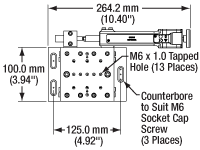
Click to Enlarge
Schematic of Metric Version
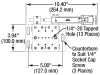
Click to Enlarge
Schematic of Imperial Version
- DRV250 Stepper Motor Provides 50 mm (1.97") Travel
- Minimum Repeatable Incremental Movement of 1 µm when used with a Stepper
Motor Controller - Thirteen 1/4"-20 (M6) Tapped Holes on the Top Surface
- Six Dowel Alignment Pins Included for Use with Mounting Accessories
- Controller Sold Separately
Thorlabs' LNR502(/M) TravelMax™ Motorized Translation Stage is designed for long travel and horizontal load capacities up to 48 kg (105 lbs). The stage is made from thermally matched steel for high stability even in less-than-ideal conditions. For compatibility with a wide variety of optomechanical setups, the stage incorporates a 3.94" x 3.94" (100.0 mm x 100.0 mm) moving platform with thirteen 1/4"-20 (M6) tapped holes and can be stacked with additional LNR502 stages in XY, XZ, and XYZ configurations using the adapters sold below.
This motorized translation stage incorporates a DRV250 Stepper Motor Drive. A controller must be purchased separately; we recommend pairing with our BSC201, BSC202, or BSC203 Stepper Motor Controllers to obtain optimal performance and a minimum achievable incremental movement of 0.05 µm.
The motor cable that is built into the DRV250 stepper motor actuator is 0.5 mm (1.64 ft) long. A 3 m (9.8 ft) PAA613 cable is included with this stage for use with our benchtop controllers. Replacement cables are available at the bottom of the page.

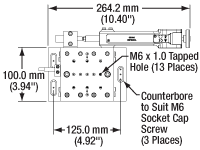
Click to Enlarge
Schematic of Metric Version
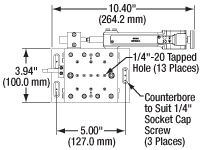
Click to Enlarge
Schematic of Imperial Version
| Encoder Specifications | |
|---|---|
| Type | Optical Grating Incremental Encoder |
| Resolution | 0.1 µm |
| Bidirectional Repeatability | ±0.75 µm |
| Bidirectional Accuracy | 6 µm |
- DRV250 Stepper Motor Provides 50 mm (1.97") Travel
- Minimum Repeatable Incremental Movement of 0.1 µm when used with a Stepper Motor Controller
- Thirteen 1/4"-20 (M6) Tapped Holes on the Top Surface
- Six Dowel Alignment Pins Included for Use with Mounting Accessories
- Controller Sold Separately
The LNR502E(/M) TravelMax™ Motorized Translation Stage combines the LNR502(/M) motorized translation stage (sold above) with an integrated linear optical encoder to reduce the minimum repeatable incremental movement from 1 µm to 0.1 µm and the bidirectional repeatability from ±3.9 µm to ±0.75 µm. This stage is designed for applications where stability, long travel, and high horizontal load capacity [48 kg (105 lbs)] need to be coupled with absolute position accuracy.
As with the LNR502 stage above, the encoded version has a 3.94" x 3.94" (100.0 mm x 100.0 mm) moving platform with thirteen 1/4"-20 (M6) tapped holes and can be stacked with additional LNR502 stages in XY, XZ, and XYZ configurations using the adapters sold below.
Dedicated software that takes full advantage of the high-resolution linear optical encoder is included. This software, when combined with one of Thorlabs' BSC201, BSC202, or BSC203 closed-loop stepper motor controllers, can provide an application solution that is fully operational out of the box.
This translation stage's linear optical encoder is directly attached to the stage's moving platform to provide the necessary feedback to the drive electronics. Since the encoder provides a direct readout of the absolute position, the mechanical positioning errors associated with backlash can be ignored.
The motor cable that is built into the DRV250 stepper motor actuator is 0.5 m (1.64 ft) long. A 3 m (9.8 ft) PAA613 cable is included with this stage for use with our benchtop controllers. Replacement cables are available at the bottom of the page.

| ENCLNR50 Encoder Kit Specifications | |
|---|---|
| On-Axis Accuracy | 10.0 µm (Typ.) |
| Repeatability | 2.0 µm (Typ.) |
| Resolution | 1.0 µm |
| Power/Data Cable (Included) | 1 m USB Cable, Type A to Micro-B |
| Power Supply (Sold Separately) | DS5 |
- Optical Position Encoder Mounts to LNR50 Series Stages
- Local Manual Control and Position Readout via Onboard Display
- Remote Control via USB and Kinesis Software
- Includes 1 m USB Cable (DS5 Power Supply Sold Separately)
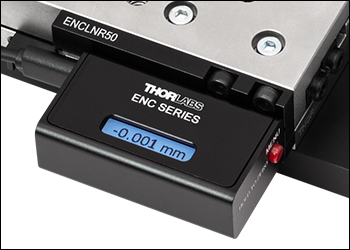
The ENCLNR50 Stage Position Encoder is designed for our LNR50 series translation stages and provides positional information in either inches or millimeters to a resolution of 1.0 µm and an accuracy of 10.0 µm. The module is comprised of the optical encoder scale bracket that attaches directly to the stage and the position reader assembly which is then attached to the bracket, as illustrated in the animation below. The module is powered via a USB micro-B connection. A 1 m long USB type A to micro-B cable is included in the kit, but the DS5 power supply is sold separately. In addition to power, the USB connection also enables the encoder module to display the stage position and control the unit via our Kinesis software. We also offer the ENCXR50 position encoder for XR50 series stages, and ENCXR25 position encoder for the XR25 series stages.
The encoder must be installed on the same side of the stage where the lock plate is initially installed, on the side opposite the adjustment knob, as shown in the photo to the right. The lock plate must first be removed before mounting the encoder.
Click to Enlarge
Closeup of the ENCLNR50 Encoder Installed on the LNR502 Stage

Click to Enlarge
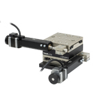
XY Configuration Using LNR50 Series Stages
- Allows for XY Translation Stage Configurations
- Dowel Pin Holes to Ensure Orthogonality (8 Dowel Pins Included)
- Dimensions (L x W x H): 3.94" x 3.94" x 0.94" (100 mm x 100 mm x 24 mm)
The LNR50P3(/M) XY Mounting Adapter provides the necessary clearance between separate LNR502(/M) and LNR502E(/M) translation stages for a left- or right-handed XY translation stage configuration. On the adapter, there are six 1/4"-20 (M6) tapped holes, four dowel pin holes, one counterbore for 1/4"-20 (M6) cap screws, and two Ø0.29" (7.5 mm) through holes. An example of an XY arrangement is shown to the right. This was assembled using the LNR50P3 Mounting Adapter, LNR50P4 Base Plate, and two LNR50 Series Translation Stages. By incorporating a third translation stage and an LNR50P2(/M) Right-Angle Bracket (sold below), a left- or right-handed XYZ translation stage can also be constructed. Dowel pins are included for easy alignment of the stage.

Click to Enlarge
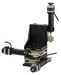
A 3-axis LNR50DD 2" travel stage shown with the manual adjusters replaced by DRV250 actuators.
- Mount an LNR502(/M) or LNR502E(/M) Translation Stage in the Vertical Plane
- Dowel Pin Holes to Ensure Orthogonality (6 Dowel Pins Included)
- Dimensions (L x W x H): 4.25" x 3.46" x 5.26" (108 mm x 88 mm x 134 mm)
The LNR50P2(/M) is an anodized aluminum right-angle bracket that orients the LNR502(/M) and LNR502E(/M) translation stages in a vertical orientation. This allows for the construction of XZ and XYZ translation stage configurations.
The base of the LNR50P2 contains six counterbored holes for 1/4"-20 (M6) cap screws, allowing it to be attached to the top of an LNR50 series stage or directly to an optical table. The vertical side has two 1/4"-20 (M6) tapped holes and eight Ø0.28" (7.0 mm) through holes.
The XYZ assembly shown to the right was constructed using the LNR50P2 Right-Angle Bracket, LNR50P3 Adapter Plate, LNR50P4 Base Plate, and three LNR502 translation stages. The LNR50P4 and LNR50P3 Mounting Adapters are sold above. Dowel pins are included with the base plate, adapter plate, and right-angle bracket to assist in alignment of the stage.

Click to Enlarge
LNR50 Series Stage with DRV250 Stepper Motor Actuator Mounted on LNR50P4 Base Plate
- Included with Stages Sold Above; Also Available Separately
- Provide Clearance Between the Stage and the Work Surface
- Dowel Pin Holes to Ensure Orthogonality (2 Dowel Pins Included)
- Made from Alumium Alloy
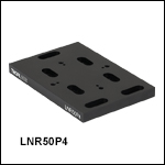
The LNR50P4(/M) base plate, included with the LNR502(/M) and LNR502E(/M) stages sold above, provides the necessary clearance between the stage and the work surface for use of the DRV250 stepper motor actuator. The LNR50P4(/M) plate has seven counterbored slots. Two pairs of 1/4"-20 tapped holes and two pairs of dowel pin holes allow a stage to be mounted and aligned in multiple orientations. Two dowel pins are included.

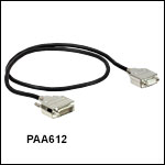
- Replacement Motor Drive Cables
- Available Lengths: 1 m (3.3') and 3 m (9.9')
These motor cables are sold as replacements for the lost or damaged PAA613 Motor Drive Cable that is included with our Motorized LNR50 Series Translation Stages. They are also compatible with our stepper motor actuators. The male end connects to the controller and the female end connects to the motor.
 Products Home


 Zoom
Zoom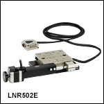
 Stepper Motor Stage