 Products Home / Motorized Stages / Motorized 25 mm or 1" Linear Translation Stages / 25 mm (0.98") Motorized Translation Stage
25 mm (0.98") Motorized Translation Stage
- 25 mm (0.98") of Travel per Axis
- 1/4"-20 or M6 Tapped Holes for Mounting Standard Optomechanics
- Sold in Single-Axis and XYZ Configurations
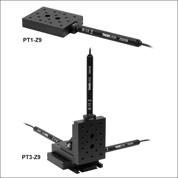
PT1-Z9
1-Axis Stage
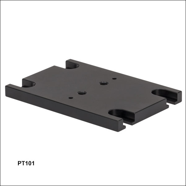
PT101
Breadboard
Mounting Adapter
PT102
Right-Angle Bracket
PT3-Z9
3-Axis Stage


Please Wait
| Key Specificationsa | |
|---|---|
| Travel Range | 25 mm (0.98") |
| Maximum Speedb | 2.6 mm/s |
| Min Repeatable Incremental Movement | 0.2 µm |
| Uncompensated/Compensated Bidirectional Repeatability |
±7 µm / ±0.8 µm |
| Uncompensated Backlash | 13 µm |
| Horizontal Load Capacity (Max) | 20 lbs (9 kg) |
| Vertical Load Capacity (Max)c | Motor Pushing Down: 7 lbs (3.2 kg) |
| Motor Pushing Up: 10 lbs (4.5 kg) |
|
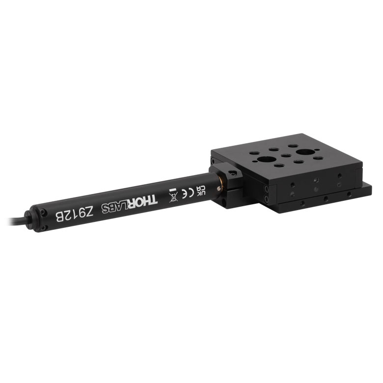
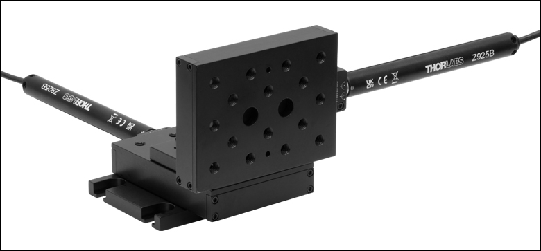
| Included Actuator | Z925B DC Motor |
| Cable Length | 485 mm (1.59 ft) |
| Required Controller | KDC101 |
| Motorized Linear Translation Stages | |
|---|---|
| 12 mm | Standard |
| 25 mm | Compact |
| Standard | |
| TravelMax | |
| 50 mm | Compact |
| Direct-Drive Servo | |
| TravelMax | |
| Long Travel: 100 mm to 300 mm | |
Features
- 25 mm (0.98") Travel Range
- Carriage Contains Sixteen 1/4"-20 (M6) Taps
- Adapters Available for Breadboard Mounting and XY, XZ, and XYZ Arrangements
- DC Servo Motor Actuator
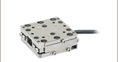
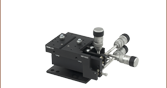
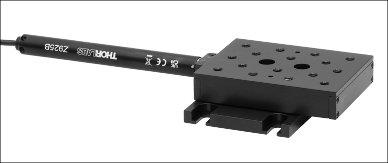
Thorlabs' Motorized Translation Stages provide electronically controlled linear motion along a well-defined axis. The PT1-Z9 (PT1/M-Z9) Single-Axis Stage provides 25 mm (0.98") of travel along one axis, while the PT3-Z9 (PT3/M-Z9) Three-Axis Stage provides travel in three dimensions. Each stage is equipped with a 3.00" x 2.00" (75.0 mm x 50.0 mm) tapped hole matrix that includes sixteen 1/4"-20 (M6) taps for compatibility with standard optomechanics.
The moving platform contains holes for alignment pins that ensure orthogonality when the stage is stacked with other stages or connected to our accessories. Horizontal loads of 20 lbs (9 kg) and vertical loads of 7 lbs (3.2 kg), when the motor is pushing down, or 10 lbs (4.5 kg), when pushing up, are supported by the actuator's inline 67.49:1 planetary gear head. Since the PT3-Z9 (PT3/M-Z9) Three-Axis Stages have the vertical actuator pushing down, the vertical load for these is 7 lbs (3.2 kg). The stages feature hardened steel linear bearings for precision motion and long life.
Mounting Adapters and Stage Combinations
Thorlabs' adapter plates and brackets provide a convenient way to mount the PT1-Z9 on an optical table or breadboard and to combine several stages into XY, XZ, or XYZ configurations. Photos of these adapters in use are shown below. For information on constructing an XYZ configuration from individual components, see the XYZ Assembly tab.
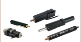
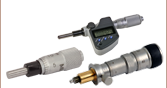
Included and Compatible Actuators
The included Z925B DC servo actuator features a 485.0 mm (1.59 ft) cable length, an internal limit switch to prevent travel outside of the intended range, and an encoder that provides 29 nm resolution (see the Specs tab for additional details). This actuator attaches to the stage using a flexure clamp that tightens around the Ø3/8" barrel. If desired, the Z925B actuator can be replaced by any manual or motorized 25 mm (0.98") actuator that includes a Ø3/8" barrel, including stepper motor actuators and manual micrometers.
Controller Options
Our KDC101 K-Cube™ Motor Controllers are required to operate these stages. Each KDC101 provides control for a single axis, with or without a PC. It is bundled with Thorlabs' Kinesis® software, which supplies out-of-the-box stage control from a PC and enables support for common programming interfaces like LabVIEW, LabWindows, and ActiveX. A USB cable is included with the KDC101. Compatible power supply options are listed below.
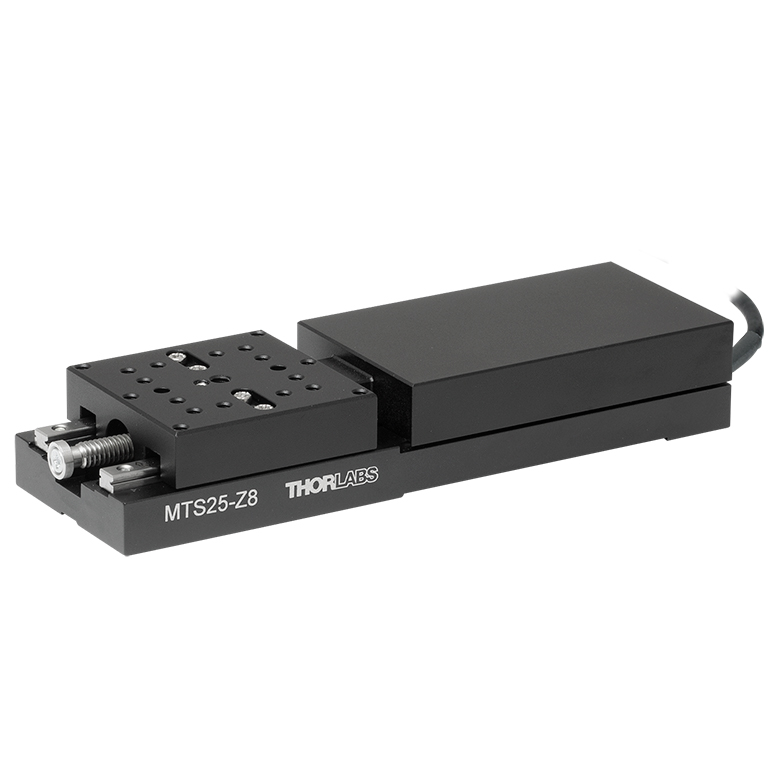
Thorlabs also manufactures the MTS25-Z8 Motorized Translation Stage, which features a built-in actuator and reduced overall package size.
| Motor Specifications | |
|---|---|
| Motor Type | DC Servo |
| Cable Length | 0.485 m (1.59 ft) |
| Feedback | Motor Mounted Rotary Encoder |
| Encoder Counts per Lead Screw Revolution | 34,555 |
| Planetary Gear Head Ratio | 67.49:1 |
| Max Recommended Current | 80 mA |
Resolution Calculation
For the Z925B motorized actuator, there are 512 encoder counts per revolution of the motor. The output shaft of the motor goes into a 67.49:1 planetary gear head. This requires the motor to rotate 67.49 times to rotate the 1.0 mm pitch lead screw one revolution. The end result is the lead screw advances by 1.0 mm.
The linear displacement of the actuator per encoder count is given by
512 x 67.49 = 34,555 encoder counts per revolution of the lead screw,
whereas the linear displacement of the lead screw per encoder count is given by
1.0 mm / 34,555 counts = 2.9 x 10⁻⁵ mm (29 nm).
| Stage Specifications | |
|---|---|
| Translation | |
| Travel Range | 25 mm (0.98") |
| Uncompensated Backlash | 13 µm |
| Residual Backlash After Compensationa | 0.7 µm |
| Min Repeatable Incremental Movement | 0.2 µm |
| Homing Repeatability | ±9 µm |
| Uncompensated/Compensated Bidirectional Repeatability | ±7 µm / ±0.8 µm |
| Resolution | 29 nm (See Calculation at Right) |
| Motion Parameters | |
| Maximum Speedb | 2.6 mm/s |
| Acceleration (Max) | 4 mm/s2 |
| Load Capacity | |
| Vertical Loadc | Motor Pushing Down: 7 lbs (3.2 kg) |
| Motor Pushing Up: 10 lbs (4.5 kg) |
|
| Horizontal Load | Max: 20 lbs (9.0 kg) |
| Straightness | |
| Orthogonality | <5 mrad |
| Angular Deviation | <250 µrad |
| Absolute On-Axis Accuracy | <130 µm |
| Percentage Accuracy (Max) | 0.52% |
| Physical | |
| Dimensions (for Single-Axis Stage) | 9.95" x 3.00" x 0.80" (252.6 mm x 76.2 mm x 20.3 mm) |
Z925B Motorized Actuator Pin Connections
D-Type Male
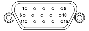
| Pin | Description | Pin | Description |
|---|---|---|---|
| 1 | Ground (Limit and Vcc) | 9 | Resistive Identification |
| 2 | Forward Limit | 10 | 5 VDC |
| 3 | Reverse Limit | 11 | Encoder Channel A |
| 4 | Reserved for Future Use | 12 | Reserved for Future Use |
| 5 | Motor (-) | 13 | Encoder Channel B |
| 6 | Reserved for Future Use | 14 | Pin 2 Identification EEPROM |
| 7 | Motor (+) | 15 | Pin 1 Identification EEPROM |
| 8 | Reserved for Future Use |
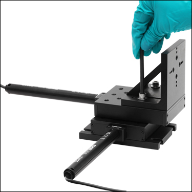
The modular design of the PT series motorized translation stages allows the assembly of 2- or 3-axis stages within minutes. Each stage comes with two precision dowel pins that allow for right- or left-handed XY configurations with excellent orthogonality. Follow the steps below to build a 3-axis XYZ translator (PT3-Z9) from individual components.
Step One
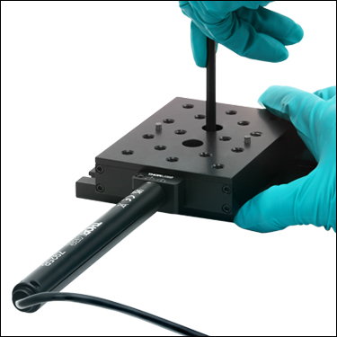
Insert the two 1/8" alignment pins into the PT101(/M) Base and then screw it onto the PT1-Z9 (PT1/M-Z9) Translation Stage using the two included 1/4"-20 (M6) cap screws. Then insert the two 1/8" alignment pins into the provided holes to ensure orthogonality of the second stage.
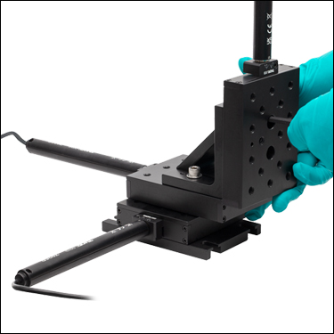
Step Two
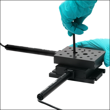
Attach the second, orthogonal PT1-Z9 (PT1/M-Z9) Translation Stage, as shown above, using two 1/4"-20 (M6) cap screws. Then insert the two 1/8" alignment pins into the provided holes for aligning the angle bracket.
Step Three
Screw the PT102(/M) Angle Bracket to the PT1-Z9 (PT1/M-Z9) Translation Stage, as shown above, using two 1/4"-20 (M6) cap screws. Then insert the two 1/8" alignment pins into the provided holes on the front face of the angle bracket for aligning the third and final stage.
Step Four
Screw the third PT1-Z9 (PT1/M-Z9) Translation Stage to the front of the PT102(/M) Angle Bracket, using two 1/4"-20 (M6) cap screws.
Thorlabs offers two platforms to drive our wide range of motion controllers: our Kinesis® software package or the legacy APT™ (Advanced Positioning Technology) software package. Either package can be used to control devices in the Kinesis family, which covers a wide range of motion controllers ranging from small, low-powered, single-channel drivers (such as the K-Cubes™ and T-Cubes™) to high-power, multi-channel, modular 19" rack nanopositioning systems (the APT Rack System).
The Kinesis Software features .NET controls which can be used by 3rd party developers working in the latest C#, Visual Basic, LabVIEW™, or any .NET compatible languages to create custom applications. Low-level DLL libraries are included for applications not expected to use the .NET framework. A Central Sequence Manager supports integration and synchronization of all Thorlabs motion control hardware.

Kinesis GUI Screen
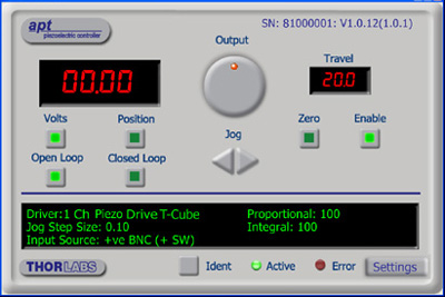
APT GUI Screen
Our legacy APT System Software platform offers ActiveX-based controls which can be used by 3rd party developers working on C#, Visual Basic, LabVIEW™, or any Active-X compatible languages to create custom applications and includes a simulator mode to assist in developing custom applications without requiring hardware.
By providing these common software platforms, Thorlabs has ensured that users can easily mix and match any of the Kinesis and APT controllers in a single application, while only having to learn a single set of software tools. In this way, it is perfectly feasible to combine any of the controllers from single-axis to multi-axis systems and control all from a single, PC-based unified software interface.
The software packages allow two methods of usage: graphical user interface (GUI) utilities for direct interaction with and control of the controllers 'out of the box', and a set of programming interfaces that allow custom-integrated positioning and alignment solutions to be easily programmed in the development language of choice.
A range of video tutorials is available to help explain our APT system software. These tutorials provide an overview of the software and the APT Config utility. Additionally, a tutorial video is available to explain how to select simulator mode within the software, which allows the user to experiment with the software without a controller connected. Please select the APT Tutorials tab above to view these videos.
Software
Kinesis Version 1.14.47
The Kinesis Software Package, which includes a GUI for control of Thorlabs' Kinesis and APT™ system controllers.
Also Available:
- Communications Protocol
Software
APT Version 3.21.6
The APT Software Package, which includes a GUI for control of Thorlabs' APT™ and Kinesis system controllers.
Also Available:
- Communications Protocol
The APT video tutorials available here fall into two main groups - one group covers using the supplied APT utilities and the second group covers programming the APT System using a selection of different programming environments.
Disclaimer: The videos below were originally produced in Adobe Flash. Following the discontinuation of Flash after 2020, these tutorials were re-recorded for future use. The Flash Player controls still appear in the bottom of each video, but they are not functional.
Every APT controller is supplied with the utilities APTUser and APTConfig. APTUser provides a quick and easy way of interacting with the APT control hardware using intuitive graphical control panels. APTConfig is an 'off-line' utility that allows various system wide settings to be made such as pre-selecting mechanical stage types and associating them with specific motion controllers.
APT User Utility
The first video below gives an overview of using the APTUser Utility. The OptoDriver single channel controller products can be operated via their front panel controls in the absence of a control PC. The stored settings relating to the operation of these front panel controls can be changed using the APTUser utility. The second video illustrates this process.
APT Config Utility
There are various APT system-wide settings that can be made using the APT Config utility, including setting up a simulated hardware configuration and associating mechanical stages with specific motor drive channels. The first video presents a brief overview of the APT Config application. More details on creating a simulated hardware configuration and making stage associations are present in the next two videos.
APT Programming
The APT Software System is implemented as a collection of ActiveX Controls. ActiveX Controls are language-independant software modules that provide both a graphical user interface and a programming interface. There is an ActiveX Control type for each type of hardware unit, e.g. a Motor ActiveX Control covers operation with any type of APT motor controller (DC or stepper). Many Windows software development environments and languages directly support ActiveX Controls, and, once such a Control is embedded into a custom application, all of the functionality it contains is immediately available to the application for automated operation. The videos below illustrate the basics of using the APT ActiveX Controls with LabVIEW, Visual Basic, and Visual C++. Note that many other languages support ActiveX including LabWindows CVI, C++ Builder, VB.NET, C#.NET, Office VBA, Matlab, HPVEE etc. Although these environments are not covered specifically by the tutorial videos, many of the ideas shown will still be relevant to using these other languages.
Visual Basic
Part 1 illustrates how to get an APT ActiveX Control running within Visual Basic, and Part 2 goes on to show how to program a custom positioning sequence.
LabVIEW
Full Active support is provided by LabVIEW and the series of tutorial videos below illustrate the basic building blocks in creating a custom APT motion control sequence. We start by showing how to call up the Thorlabs-supplied online help during software development. Part 2 illustrates how to create an APT ActiveX Control. ActiveX Controls provide both Methods (i.e. Functions) and Properties (i.e. Value Settings). Parts 3 and 4 show how to create and wire up both the methods and properties exposed by an ActiveX Control. Finally, in Part 5, we pull everything together and show a completed LabVIEW example program that demonstrates a custom move sequence.
Part 1: Accessing Online Help
Part 2: Creating an ActiveX Control
Part 3: Create an ActiveX Method
Part 4: Create an ActiveX Property
Part 5: How to Start an ActiveX Control
The following tutorial videos illustrate alternative ways of creating Method and Property nodes:
Create an ActiveX Method (Alternative)
Create an ActiveX Property (Alternative)
Visual C++
Part 1 illustrates how to get an APT ActiveX Control running within Visual C++, and Part 2 goes on to show how to program a custom positioning sequence.
MATLAB
For assistance when using MATLAB and ActiveX controls with the Thorlabs APT positioners, click here.
To further assist programmers, a guide to programming the APT software in LabVIEW is also available here.
| Posted Comments: | |
Christopher Schnaitmann
(posted 2019-10-21 18:08:02.54) Dear Sir or Madam,
is this stage compatible with the Sutter MP-285 Controller and what is the expected min achievable incremental movement in this configuration?
Kind regards,
Christopher Schnaitmann rmiron
(posted 2019-10-23 04:15:05.0) Response from Radu at Thorlabs: Hello Christopher. The short answer is no. From what I can see on Sutter's website, MP-285 is a stepper motor controller. PT1-Z8/M uses a brushed DC servo motor. Consequently, it requires very different drive electronics. Mike Lin
(posted 2019-10-05 11:37:36.747) 1.Does this product have CE certification?
2.Does Thorlab have agent in Taiwan? AManickavasagam
(posted 2019-10-08 04:47:01.0) Response from Arunthathi at Thorlabs: Thanks for your query. Yes, we do have CE certificaton. We do not have an agent but we do support and ship to Taiwan. If required please contact techsupport@thorlabs.com for further assistance. user
(posted 2019-08-12 06:25:58.077) I want to buy this motorized 2D linear stage, MTS25-Z8 but I have few concerns, Can it generate triggers for synchronizing with other hardware devices? rmiron
(posted 2019-08-12 12:23:04.0) Response from Radu at Thorlabs: You can set the stage, from Kinesis, to be in one of 8 different Trigger Out modes. KDC101 can send triggers out when the stage reaches max velocity, when it is in motion, when it passes a point while going forward (or in reverse, or both) or when it reaches the forward limit switch (or the reverse, or both). The trigger polarity can also be set from Kinesis. For more freedom you could also use Kinesis' APIs to set the state of the trigger out port as desired. pallav.kant
(posted 2014-01-31 07:40:48.45) I am looking to make a XY motion using 2 PT1 Z8 translators, but facing issues in creating assembly, can you please explain how to create XY translator assembly using suitable diagrams.
Thanks sharrell
(posted 2014-02-05 08:41:46.0) Response from Sean at Thorlabs: Thank you for your feedback. We have instructions for attaching the manual versions of these stages into XYZ configurations here: http://www.thorlabs.com/newgrouppage9.cfm?objectgroup_id=706, and click on the "XYZ Assembly" tab. We are working to duplicate this content for the motorized stages. jlow
(posted 2012-10-05 08:58:00.0) Response from Jeremy at Thorlabs: We will update the webpage to include more information about the motor. The PT1/M-Z8 uses the Z825B motor, which has a bidirectional repeatability of <1.5µm. You can also find out about other specifications for this motor at http://www.thorlabs.com/NewGroupPage9.cfm?ObjectGroup_ID=1883&pn=Z825B. maarten.van.kampen
(posted 2012-10-05 02:30:44.0) Dear madam/sir,
For most motorized translators a 'bidirectional repeatability' is specified. this is a very useful number, since it will tell me how close I can approximate an absolute position. This product range only specifies a minimum step of 29 nm (calculated), which will be a highly optimistic number.
What is the repeatability of this device series? tcohen
(posted 2012-09-06 15:12:00.0) Response from Tim at Thorlabs to Mixalis: Thank you for contacting us. I would like to go over your measurement setup with you and have contacted you directly to do so. If the stage is not performing to spec we will of course take it in for evaluation and repair. mikeloul
(posted 2012-09-05 14:42:28.0) Dear Sir/Madam,
I had bought some PT1/M-Z8 2-e months ago but I'm encountering some problems concerning the angular deviation. In the space of 0 - 25,4mm the laser beam goes up 1,5mm measured in a distance of 1850mm, which means that the angular deviation is approx 800µrad, instead of <250 µrad that you refer at the specs. The laser beam seems to rise when I move the motors back. Have you noticed something like that?
Best regards
Mixalis |
Motorized Linear Translation Stages
Thorlabs' motorized linear translation stages are offered in a range of maximum travel distances, from a stage with 20 µm of piezo translation to our 600 mm direct drive stage. Many of these stages can be assembled in multi-axis configurations, providing XY or XYZ translation. For fiber coupling applications, please see our multi-axis stages, which offer finer adjustment than our standard motorized translation stages. In addition to motorized linear translation stages, we offer motorized rotation stages and goniometers. We also offer manual translation stages.
Piezo Stages
These stages incorporate piezoelectric elements in a variety of drive mechanisms. ORIC® stages incorporate piezo inertia drives that use "stick-slip" friction properties to obtain extended travel ranges. Our Nanoflex™ translation stages use standard piezo chips along with manual actuators. Elliptec® stages use resonant piezo motors to push and pull the moving platform through resonant elliptical motion. Our LPS710E z-axis stage features a mechanically amplified piezo design and includes a matched controller.
| Piezoelectric Stages | ||||
|---|---|---|---|---|
| Product Family | ORIC® PDXZ1 Closed-Loop 4.5 mm Vertical Stage |
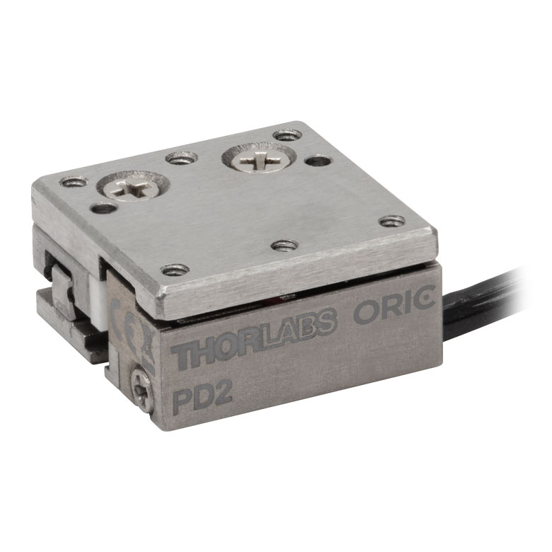
ORIC® PD2 Open-Loop 5 mm Stage |
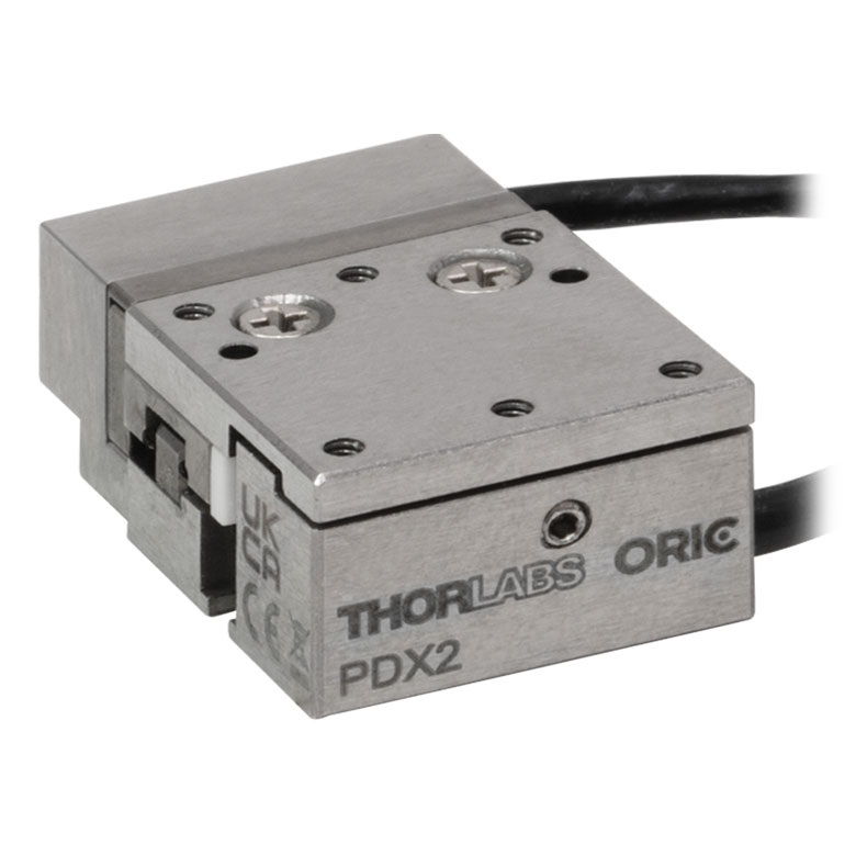
ORIC® PDX2 Closed-Loop 5 mm Stage |
|
| Click Photo to Enlarge |
 |
 |
 |
|
| Travel | 4.5 mm | 5 mm | ||
| Speed | 1 mm/s (Typ.)a | 10 mm/s (Typ. Max)b | 8 mm/s (Typ.)c | |
| Drive Type | Piezoelectric Inertia Drive | |||
| Possible Axis Configurations | Z | X, XY, XYZ | ||
| Mounting Surface Size |
45.0 mm x 42.0 mm | 13 mm x 13 mm | ||
| Additional Details | ||||
| Piezoelectric Stages | |||||
|---|---|---|---|---|---|
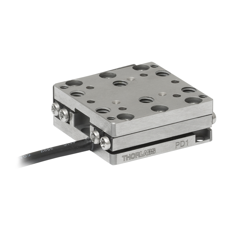
| Product Family | ORIC® PD1 Open-Loop 20 mm Stage |
ORIC® PD1D Open-Loop 20 mm Monolithic XY Stage |
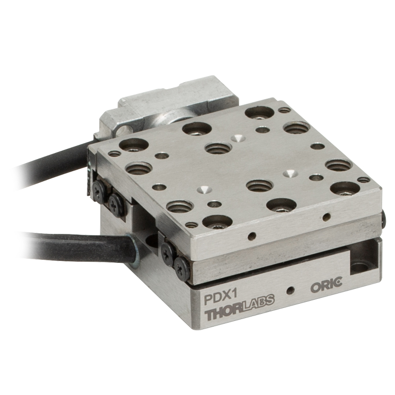
ORIC® PDX1 Closed-Loop 20 mm Stage |
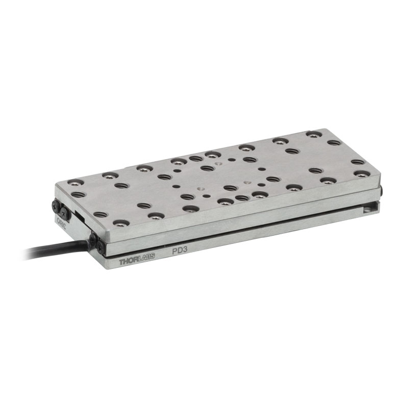
ORIC® PD3 Open-Loop 50 mm Stage |
|
| Click Photo to Enlarge |
 |
 |
 |
 |
|
| Travel | 20 mm | 50 mm | |||
| Speed | 3 mm/s (Typ. Max)a | 20 mm/s (Typ. Max)b | 10 mm/sc | ||
| Drive Type | Piezoelectric Inertia Drive | ||||
| Possible Axis Configurations | X, XY, XYZ | XY, XYZ | X, XY, XYZ | X, XY, XYZ | |
| Mounting Surface Size |
30 mm x 30 mm | 80 mm x 30 mm | |||
| Additional Details | |||||
| Piezoelectric Stages | ||||||
|---|---|---|---|---|---|---|
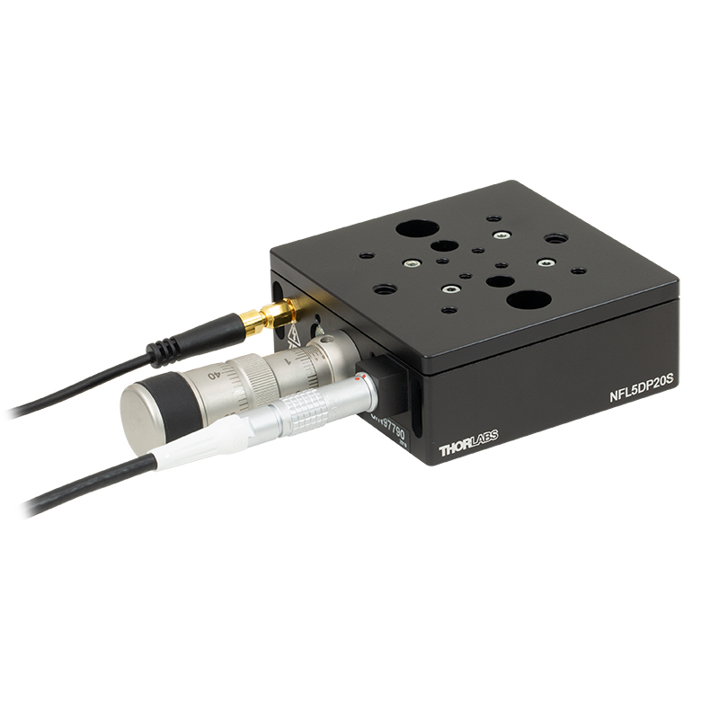
| Product Family | Nanoflex™ 20 µm Stage with 5 mm Actuator |
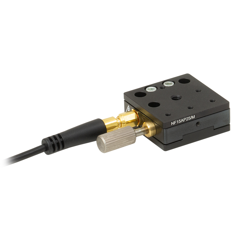
Nanoflex™ 25 µm Stage with 1.5 mm Actuator |
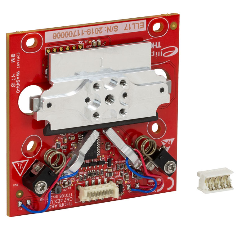
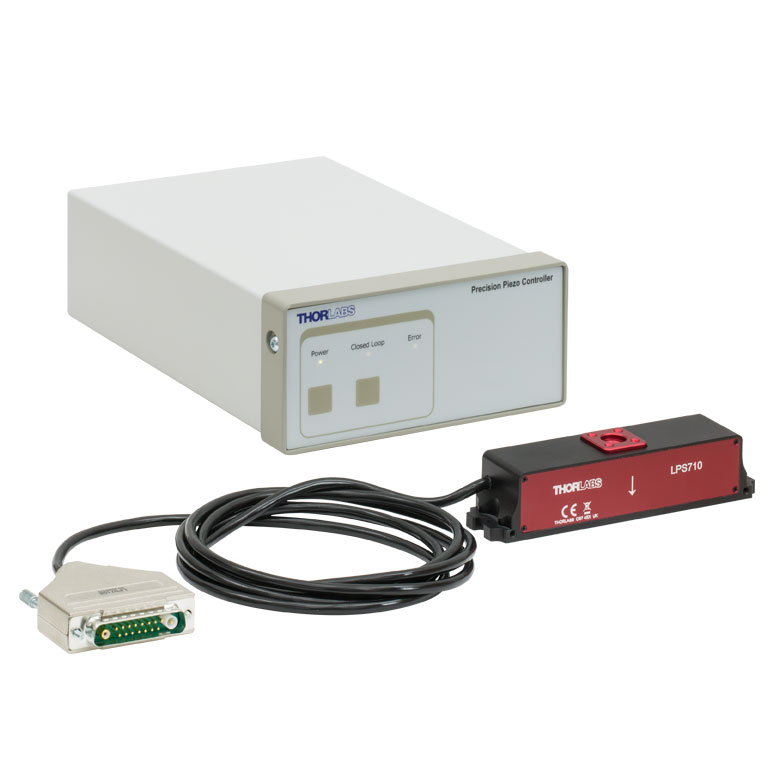
Elliptec® 28 mm Stage | Elliptec® 60 mm Stage | LPS710E 1.1 mm Vertical Stage | |
| Click Photo to Enlarge |
 |
 |
 |
 |
 |
|
| Travel | 20 µm + 5 mm Manual | 25 µm + 1.5 mm Manual | 28 mm | 60.0 mm | 1.1 mm | |
| Maximum Velocity | - | 180 mm/s | 90 mm/s | - | ||
| Drive Type | Piezo with Manual Actuator | Resonant Piezoelectric Motor | Amplified Piezo | |||
| Possible Axis Configurations | X, XY, XYZ | X | Z | |||
| Mounting Surface Size | 75 mm x 75 mm | 30 mm x 30 mm | 15 mm x 15 mm | 21 mm x 21 mm | ||
| Additional Details | ||||||
Stepper Motor Stages
These translation stages feature removable or integrated stepper motors and long travel ranges up to 300 mm. Many of these stages either have integrated multi-axis capability (PLSXY) or can be assembled into multi-axis configurations (PLSX, LNR Series, NRT Series, and LTS Series stages). The MLJ150 stage also offers high load capacity vertical translation.
| Stepper Motor Stages | |||||
|---|---|---|---|---|---|
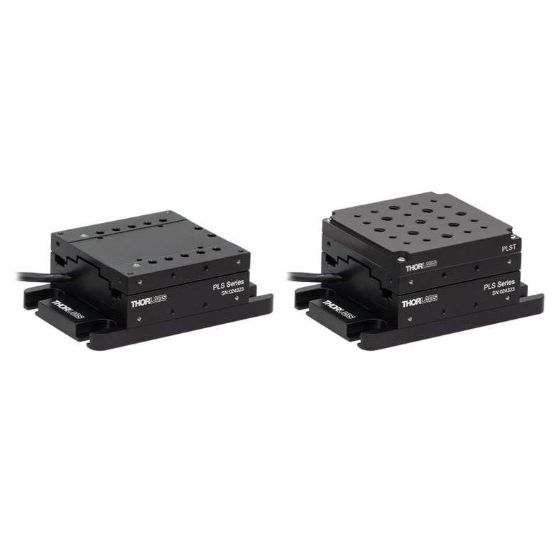
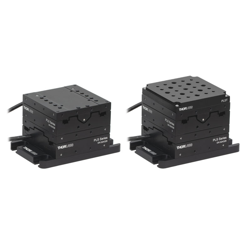
| Product Family | PLSX with and without PLST(/M) Top Plate 1" Stage |
PLSXY with and without PLST(/M) Top Plate 1" Stage |
LNR Series 25 mm Stage |
LNR Series 50 mm Stage |
|
| Click Photo to Enlarge |
 |
 |
 |
 |
|
| Travel | 1" | 25 mm | 50 mm | ||
| Maximum Velocity | 7.0 mm/s | 2.0 mm/s | 50 mm/s | ||
| Possible Axis Configurations |
X, XY | X, XY, XYZ | X, XY, XYZ | ||
| Mounting Surface Size |
3" x 3" | 60 mm x 60 mm | 100 mm x 100 mm | ||
| Additional Details | |||||
| Stepper Motor Stages | ||||||
|---|---|---|---|---|---|---|
| Product Family | NRT Series 100 mm Stage |
NRT Series 150 mm Stage |
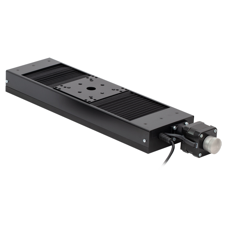
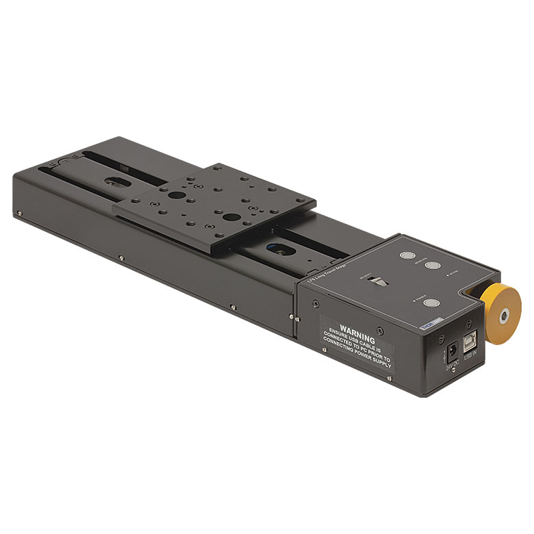
LTS Series 150 mm Stage |
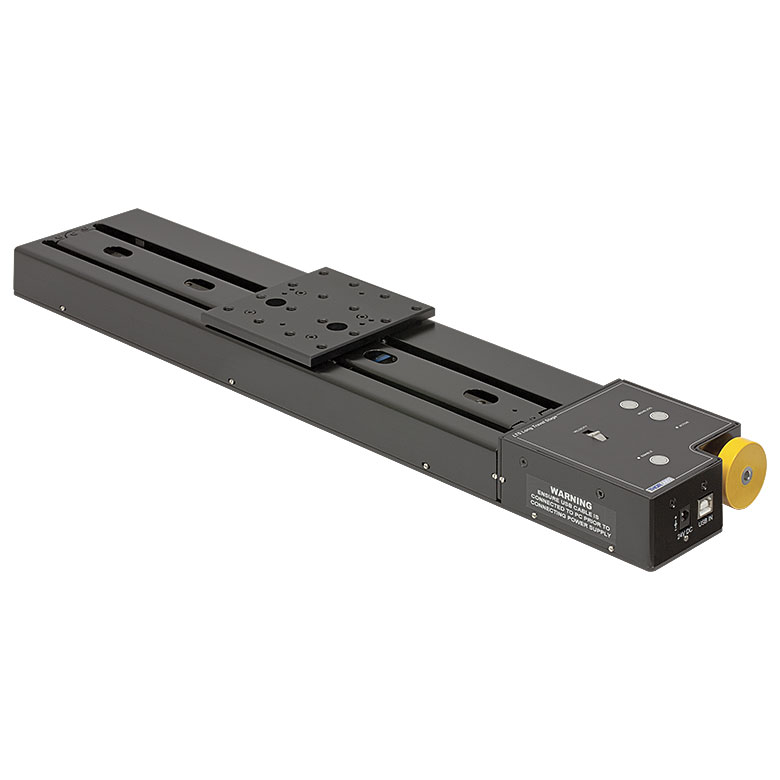
LTS Series 300 mm Stage |
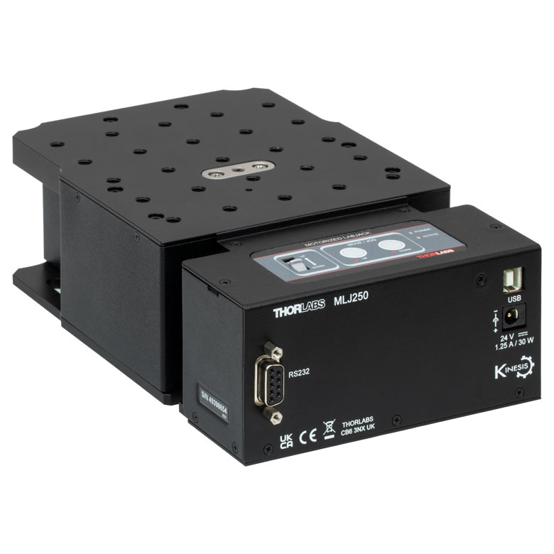
MLJ250 50 mm Vertical Stage |
|
| Click Photo to Enlarge |
 |
 |
 |
 |
 |
|
| Travel | 100 mm | 150 mm | 150 mm | 300 mm | 50 mm | |
| Maximum Velocity | 30 mm/s | 50 mm/s | 3.0 mm/s | |||
| Possible Axis Configurations |
X, XY, XYZ | X, XY, XYZ | Z | |||
| Mounting Surface Size |
84 mm x 84 mm | 100 mm x 90 mm | 148 mm x 131 mm | |||
| Additional Details | ||||||
DC Servo Motor Stages
Thorlabs offers linear translation stages with removable or integrated DC servo motors. These stages feature low profiles and many can be assembled in multi-axis configurations.
| DC Servo Motor Stages | ||||
|---|---|---|---|---|
| Product Family | MT Series 12 mm Stages |
PT Series 25 mm Stages |
MTS Series 25 mm Stage |
MTS Series 50 mm Stage |
| Click Photo to Enlarge |
 |
 |
 |
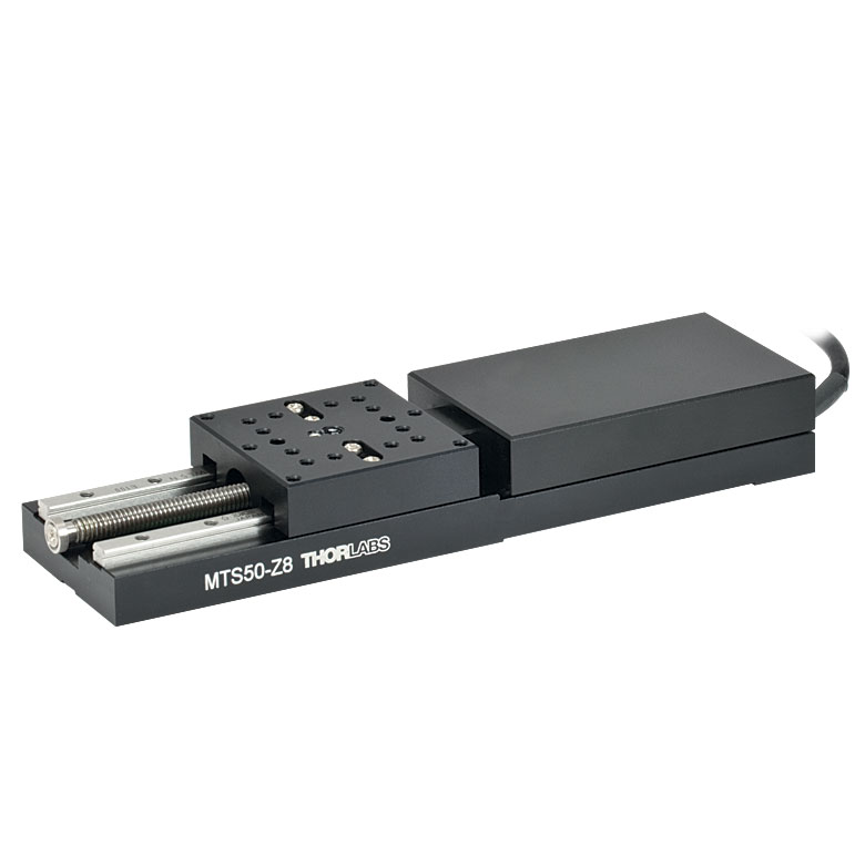 |
| Travel | 12 mm | 25 mm | 25 mm | 50 mm |
| Maximum Velocity | 2.6 mm/s | 2.4 mm/s | ||
| Possible Axis Configurations | X, XY, XYZ | X, XY, XYZ | ||
| Mounting Surface Size |
61 mm x 61 mm | 101.6 mm x 76.2 mm | 43 mm x 43 mm | |
| Additional Details | ||||
| DC Servo Motor Stages | ||||
|---|---|---|---|---|
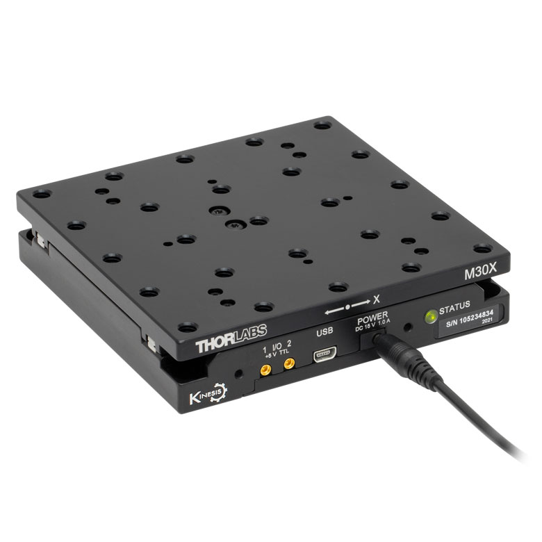
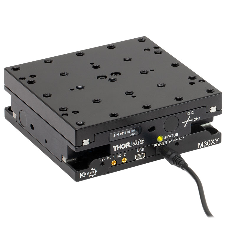
| Product Family | M30 Series 30 mm Stage |
M30 Series 30 mm Monolithic XY Stage |
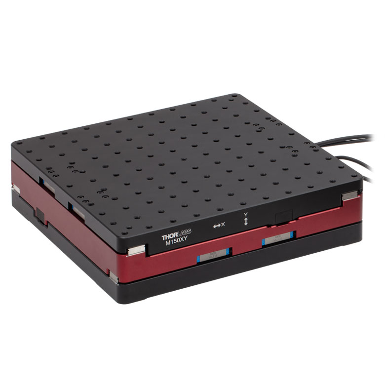
M150 Series 150 mm XY Stage |
KVS30 30 mm Vertical Stage |
| Click Photo to Enlarge |
 |
 |
 |
 |
| Travel | 30 mm | 150 mm | 30 mm | |
| Maximum Velocity | 2.4 mm/s | X-Axis: 170 mm/s Y-Axis: 230 mm/s |
8.0 mm/s | |
| Possible Axis Configurations | X, Z | XY, XZ | XY | Z |
| Mounting Surface Size |
115 mm x 115 mm | 272.4 mm x 272.4 mm | 116.2 mm x 116.2 mm | |
| Additional Details | ||||
Direct Drive Stages
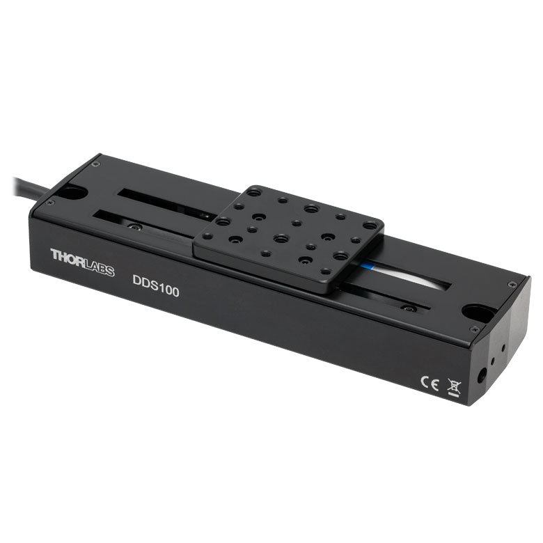
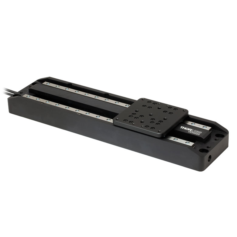
These low-profile stages feature integrated brushless DC servo motors for high speed translation with zero backlash. When no power is applied, the platforms of these stages have very little inertia and are virtually free running. Hence these stages may not be suitable for applications where the stage's platform needs to remain in a set position when the power is off. We do not recommend mounting these stages vertically.
| Direct Drive Stages | |||||
|---|---|---|---|---|---|
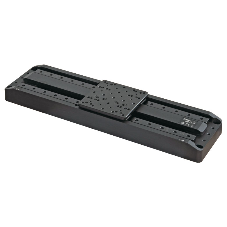
| Product Family | DDS Series 50 mm Stage |
DDS Series 100 mm Stage |
DDS Series 220 mm Stage |
DDS Series 300 mm Stage |
DDS Series 600 mm Stage |
| Click Photo to Enlarge |
 |
 |
 |
 |
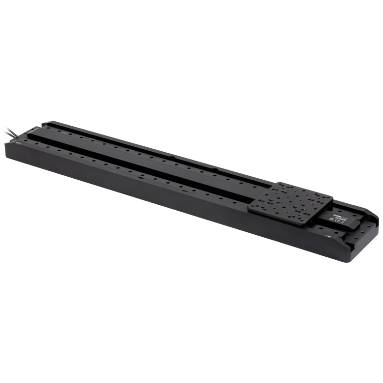 |
| Travel | 50 mm | 100 mm | 220 mm | 300 mm | 600 mm |
| Maximum Velocity | 500 mm/s | 300 mm/s | 400 mm/s | 400 mm/s | |
| Possible Axis Configurations | X, XY | X, XY | X | X | |
| Mounting Surface Size | 60 mm x 52 mm | 88 mm x 88 mm | 120 mm x 120 mm | ||
| Additional Details | |||||
 Motorized Translation Stages")
 Zoom
Zoom
Click for Details
Schematic of Metric Single-Axis Stage

Click for Details
Schematic of Imperial Single-Axis Stage
- Single-Axis and Three-Axis Versions
- Z925B DC Servo Actuator Provides 25 mm (0.98") Travel per Axis
- Includes Two Alignment Pins per Axis for Stage Stacking and Mounting Accessories
- Controller and Power Supply Sold Separately
Thorlabs' PT1-Z9 (PT1/M-Z9) Single-Axis and PT3-Z9 (PT3/M-Z9) Three-Axis Motorized Translation Stages provide linear, orthogonal motion in one or three dimensions. Sixteen 1/4"-20 (M6) tapped holes allow easy integration with a wide variety of common optomechanical setups. The stages feature hardened steel linear bearings for precision motion and long life.
The PT1-Z9 stage is designed for single-axis translation. For applications requiring XY motion, simply purchase two PT1-Z9 stages and stack them using the provided alignment pins to ensure orthogonality. If XYZ motion is desired, then we recommend the PT3-Z9 stage. In addition to alignment pins for all three axes, the PT3-Z9 includes a PT101(/M) Base Plate and a PT102(/M) Right-Angle Bracket. For more details on these accessories, please read below. Two oversized 1/4"-20 (M6) counterbores in each single-axis stage allow the stage to be directly attached to a mounting adapter (sold below) or a metric or imperial breadboard with user-supplied cap screws.
Each axis requires a standalone controller unit and power supply to operate. For this purpose, we recommend our KDC101 K-Cube™ Motor Controller, which is described in more detail below.
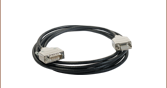
The motor cable that is built in to the Z925B actuator is 0.485 m (1.59 ft) long. If more length is required for your application, we recommend our PAA632 Extension Cable, which provides an additional 2.5 m (8.20 ft). It is sold at the bottom of this page.

 Zoom
Zoom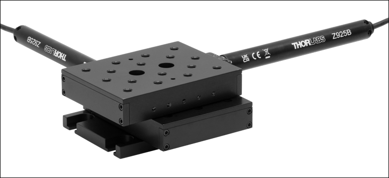
Click to Enlarge
XY-Configured PT1-Z9 Stages on PT101 Base Plate
Click to Enlarge
PT101 Base Plate Provides Easily Accessed Counterbored Slots
- Mount a PT1-Z9 Single-Axis Stage to a Breadboard or Optical Table
- Contains Four 1/4" (M6) Counterbore Slots for Imperial and Metric Compatibility
- Alignment Holes and Dowel Pins Ensure Parallelism
The PT101(/M) Base Plate is ideal for XY configurations or already assembled XYZ multi-axis configurations where the standard counterbores in the middle of the stages are obstructed. Although the PT1-Z9 (PT1/M-Z9) Single-Axis Stage sold above can be directly mounted to a breadboard or optical table, mounting requires unobstructed access to the two bores in the middle of the moving platform. This base plate allows an attached stage to be positioned on a breadboard without having to disassemble a setup that already exists on the moving platform. This plate is included with the purchase of a PT3-Z9 (PT3/M-Z9) Three-Axis Stage.
The bottom of the translation stage is connected to the base plate using two 1/4"-20 (M6) cap screws. The base plate includes two alignment holes for the alignment pins included with the PT1-Z9 stage, which together ensure that the translation axis is parallel to the plate.

 Zoom
Zoom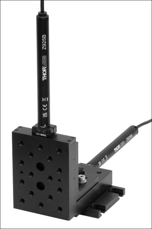
Click to Enlarge
XZ-Configured PT1-Z9 Stages
Click to Enlarge
XY-Configured PT1-Z9 Stages with Vertical Mounting Surface
- Mount a PT1-Z9 Translation Stage in the Vertical Plane
- Used for XY, XZ, or XYZ Configurations
- Contains Alignment Holes that Ensure Orthogonality
The PT102(/M) Right-Angle Bracket orients a PT1-Z9 (PT1/M-Z9) Single-Axis Stage in the vertical plane, allowing the construction of XY, XZ, or XYZ arrangements of PT1-Z9 stages. Two examples are shown to the right. This bracket is included with the purchase of a PT3-Z9 Three-Axis Stage. This angle bracket is also compatible with our manual and motorized MT series translation stages that offer 1/2" (25 mm) of travel. This allows stages with different travel ranges to be easily connected within the same mechanical system.
To begin the assembly process, insert the two alignment pins provided with the PT1-Z9 stage into the stage's alignment holes. Then position the bracket's alignment holes above the pins. The bracket can be fastened down using two 1/4"-20 (M6) cap screws. At this point, the bracket's vertical mounting surface will accommodate a stage that is attached horizontally (for XY configurations) or vertically (for XZ or XYZ configurations). For details, please see the XYZ Assembly tab.

 Zoom
Zoom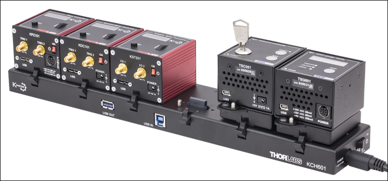 Click to Enlarge
KCH601 USB Controller Hub (Sold Separately) with Installed K-Cube and T-Cube™ Modules (T-Cubes Require the KAP101 Adapter)
- Front Panel Velocity Wheel and Digital Display for Controlling Motorized Stages or Actuators
- Two Bidirectional Trigger Ports to Read or Control External Equipment
- Interfaces with Computer Using Included USB Cable
- Fully Compatible with Kinesis® or APT™ Software Packages
- Compact Footprint: 60.0 mm x 60.0 mm x 49.2 mm (2.42" x 2.42" x 1.94")
- Power Supply Not Included (See Below)
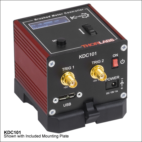
Thorlabs' KDC101 K-Cube Brushed DC Motor Controller provides local and computerized control of a single motor axis. It features a top-mounted control panel with a velocity wheel that supports four-speed bidirectional control with forward and reverse jogging as well as position presets. A backlit digital display is also included that can have the backlit dimmed or turned off using the top-panel menu options. The front of the unit contains two bidirectional trigger ports that can be used to read a 5 V external logic signal or output a 5 V logic signal to control external equipment. Each port can be independently configured.
The unit is fully compatible with our new Kinesis software package and our legacy APT control software. Please see the Motion Control Software tab for more information.
Please note that this controller does not ship with a power supply. Compatible power supplies are listed below. Additional information can be found on the main KDC101 DC Servo Motor Controller page.

 Zoom
Zoom
Click for Details
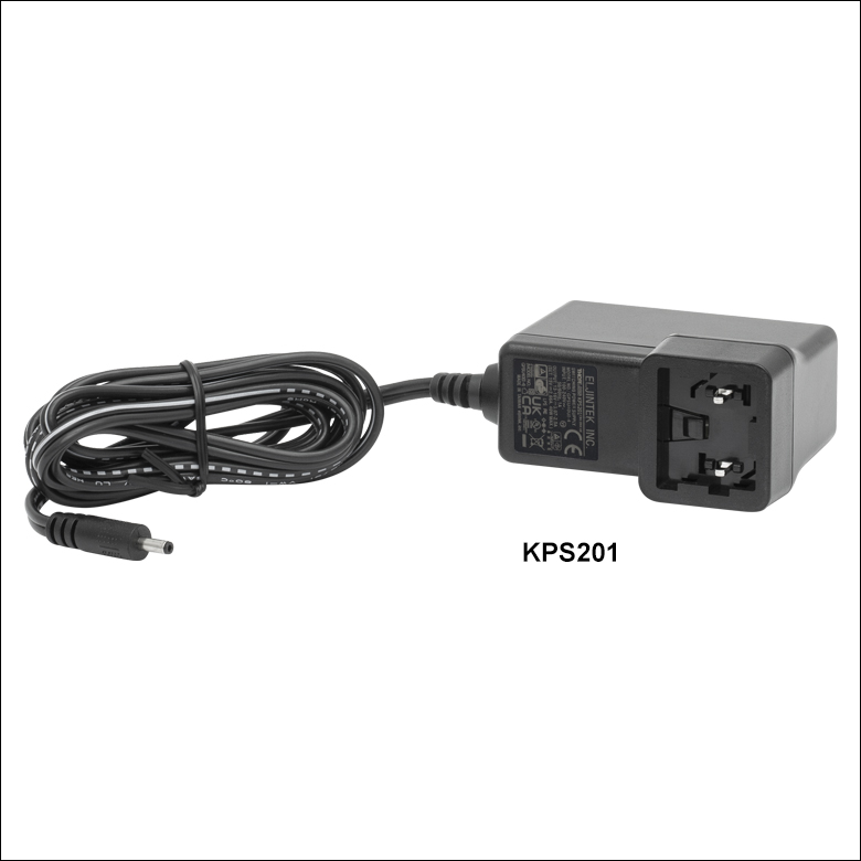
Each KPS201 power supply includes one region-specific adapter, which can be selected upon checkout.
Click to Enlarge
The KPS201 Power Supply Unit
- Individual Power Supply
- KPS201: For K-Cubes™ or T-Cubes™ with 3.5 mm Jacks
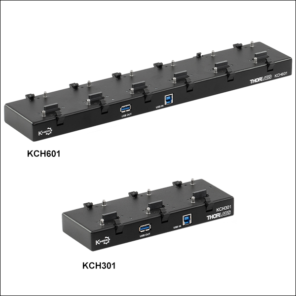
- USB Controller Hubs Provide Power and Communications
- KCH301: For up to Three K-Cubes or T-Cubes
- KCH601: For up to Six K-Cubes or T-Cubes
The KPS201 power supply outputs +15 VDC at up to 2.66 A and can power a single K-Cube or T-Cube with a 3.5 mm jack. It plugs into a standard wall outlet.
The KCH301 and KCH601 USB Controller Hubs each consist of two parts: the hub, which can support up to three (KCH301) or six (KCH601) K-Cubes or T-Cubes, and a power supply that plugs into a standard wall outlet. The hub draws a maximum current of 10 A; please verify that the cubes being used do not require a total current of more than 10 A. In addition, the hub provides USB connectivity to any docked K-Cube or T-Cube through a single USB connection.
For more information on the USB Controller Hubs, see the full web presentation.

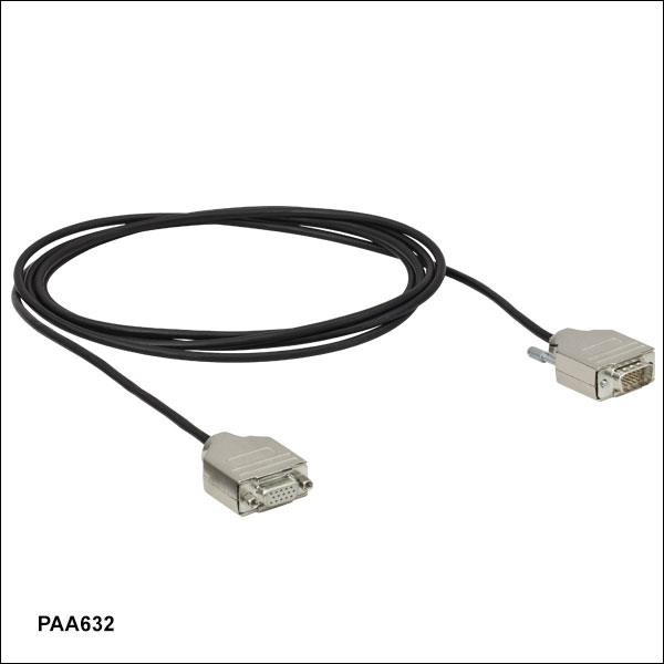 Zoom
ZoomThe PAA632 Extension Cable provides an additional 2.5 m (8.20 ft) of cable length for the 15-pin D-type connectors used throughout our motorized actuator selection. The male end connects to the controller, while the female end connects to the motor.