 Products Home / Motorized Stages / Long Travel Linear Motorized Stages (>100 mm) / 150 mm Linear Translation Stage with Integrated Controller, Stepper Motor
150 mm Linear Translation Stage with Integrated Controller, Stepper Motor
- Integrated Controller with Keypad and Remote USB Control
- Stackable in XY, XZ, and XYZ Configurations
- Calibrated On-Axis Accuracy of <±5 µm
- Horizontal Load Capacity of 15 kg (33.1 lbs)
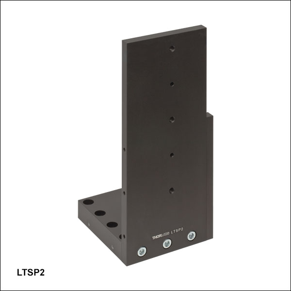
LTSP2
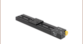
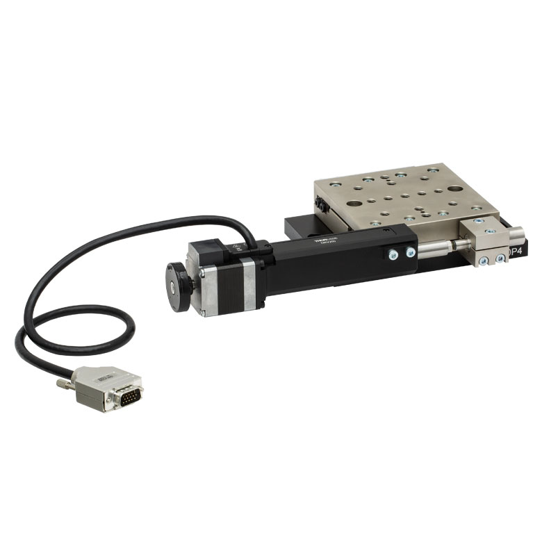
Right-Angle Bracket
Application Idea
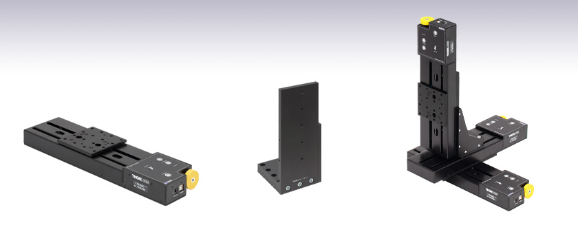
Three LTS150C Stages in
XYZ Configuration, Using an
LTSP1 XY Adapter Plate and
LTSP2 Right-Angle Bracket
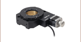
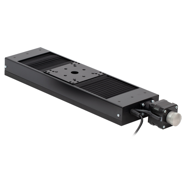
LTS150C
150 mm Translation Stage


Please Wait
| Key Specificationsa | |
|---|---|
| Travel Range | 150 mm (5.9") |
| Horizontal Velocity (Max) | 50 mm/s |
| Vertical Velocity (Max) | 3 mm/s |
| Minimum Achievable Incremental Movementb |
0.1 µm |
| Minimum Repeatable Incremental Movementc |
4 µm |
| Calibrated Accuracyd | < ±5.0 µm |
| Bidirectional Repeatabilitye | < ±2 µm |
| Backlashf | 2 µm |
| Load Capacity (Max) - Stage Mounted Horizontally |
15 kg (33.1 lbs) |
| Load Capacity (Max) - Stage Mounted Vertically |
4 kg (8.8 lbs) |
| Actuator Type | Stepper Motor |
| Included USB Cable Length | 1.5 m (4.9 ft) |
Features
- 150 mm Travel Range
- Integrated Stepper Motor Controller
- Control via Manual Keypad or Remote PC
- Load Capacity
- Horizontally Mounted: 15 kg (33.1 lbs)
- Vertically Mounted: 4 kg (8.8 lbs)
- Maximum Velocity of 50 mm/s
- Bidirectional Repeatability of 2 µm
- XY, XZ, and XYZ Configurable
- 1/4"-20 or M6 Tapped Holes for Mounting Standard Optomechanics
- Power Supply Included
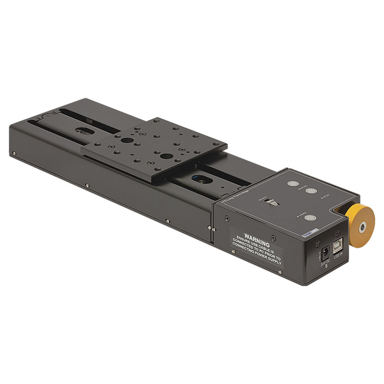
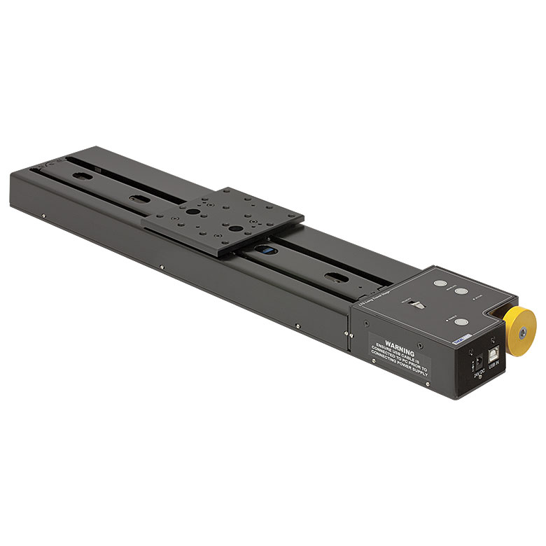
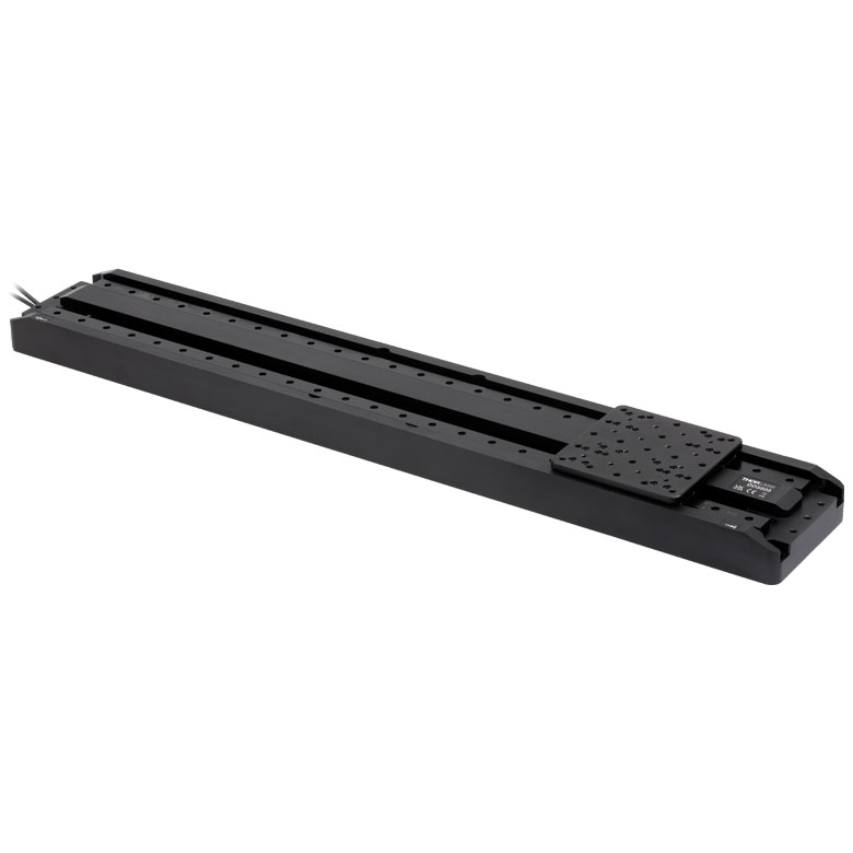
Thorlabs' LTS150C(/M) Linear Translation Stage with Integrated Controller is optimized for applications requiring high load capacity and high resolution, such as measurement and inspection. It provides 150 mm of linear travel for loads as great as 15 kg (33.1 lbs) when mounted horizontally and 4 kg (8.8 lbs) when mounted vertically. Each stage features an accuracy within ±5.0 µm when the unit-specific calibration files are used with the Thorlabs Kinesis or APT™ software. Due to the stepper motor design, the platform position remains fixed when no power is supplied to the stage, unlike with DC servo motor translation stages.

Click to Enlarge
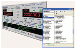
Integrated Controller with Manual and Remote PC Control
The LTS150C(/M) stage features an integrated electronic controller that can be controlled remotely using a PC or manually via the buttons and velocity potentiometer on the control keypad (see photo to the left). Parameter settings can be adjusted on the PC and stored in non-volatile memory within the unit itself. When the unit is powered up, these settings are applied automatically. This is particularly useful when the stage is being used manually in the absence of a PC and USB link.
| Motorized Linear Long-Travel Stages | |
|---|---|
| 100 mm | Stepper |
| DC Servo | |
| 150 mm | Stepper |
| Stepper with Integrated Controller | |
| 220 mm | DC Servo |
| 300 mm | Stepper with Integrated Controller |
| DC Servo | |
| 600 mm | DC Servo |
| Optical Delay Line Kits | |
| Other Translation Stages | |
The stage is lightweight, compact, and robust with high performance over the full travel range. The heavy-duty aluminum construction and 40 mm moving platform height makes this stage ideal for applications where space is limited. Integrated magnetic limit switches allow homing and overdrive protection in both directions. A precision-ground lead screw delivers smooth, virtually noise-free movement. The power supply provided with the stage operates with 90 - 264 VAC input voltages (47 - 63 Hz) and is shipped with a location-specific power cord.
Thorlabs also offers the LTS300C(/M) Linear Translation Stage with Integrated Controller, which features 300 mm of travel.
Calibration Files
Each LTS150C(/M) Linear Translation Stage is calibrated during manufacturing. Calibration enables the controller to correct for any mechanical errors present in the system. Mechanical components, such as the lead screw and linkages, can be machined only within a certain tolerance. These mechanical errors result in deviations of the actual position from the commanded position. However, the deviations are repeatable and can be compensated for using the Kinesis or APT software and included calibration files. These files are used by the APT software to convert the position entered by the user into the required mechanical motion. The calibration files can be downloaded by clicking on the red Docs icon  )
)
The use of calibration files is optional. Without them, the repeatability and resolution of the stage are unaffected, but no compensations are made to enhance the accuracy. Each stage is calibrated at the factory, giving a typical on-axis accuracy of 20 µm without the use of the calibration files.
Stage Combinations
If an XY configuration is desired, any combination of LTS150C(/M) and LTS300C(/M) Linear Positioning Stages (the latter features a 300 mm travel range) can be mounted atop one another using the LTSP1(/M) XY Adapter Plate (sold below). XZ and XYZ configurations are possible using our LTSP2(/M) Z-Axis Bracket, which orients an LTS150C(/M) stage in the vertical plane. Please note that stages and adapters with imperial or metric taps are only compatible with other stages and adapters featuring the same thread standards.
Software
The ActiveX® APT system software is also compatible with other APT family controllers, including our multi-channel controllers, rack-based controller, and smaller, optical-table-mountable K-Cube™ controllers. This single unified software offering allows seamless mixing of the LTS150C(/M) stages with any APT benchtop, tabletop, or rack-based controllers.
| Stage Specifications | ||
|---|---|---|
| Translation | ||
| Travel Range | 150 mm (5.9") | |
| Bidirectional Repeatabilitya | < ±2 µm | |
| Backlashb | 2 µm | |
| Maximum Velocityc | 50 mm/s Horizontal, 3 mm/s Vertical | |
| Velocity Stability | ±1 mm/s | |
| Maximum Accelerationc | 50 mm/s2 Horizontal, 5 mm/s2 Vertical | |
| Accuracy | ||
| Min Achievable Incremental Movementd | 100 nm | |
| Min Repeatable Incremental Movemente | 4 µm | |
| Calibrated On-Axis Accuracy | < ±5.0 µm | |
| Max Percentage Accuracyf | 0.13% | |
| Home Location Accuracy | ±0.6 µm | |
| Pitchg | <0.016° (279 µrad) | |
| Yawg | <0.05° (873 µrad) | |
| Load Capacity | ||
| Load Capacity (Max) - Stage Mounted Horizontally |
Max: 15 kg (33.1 lbs) Recommended: <12 kg (26.5 lbs) |
|
| Load Capacity (Max) - Stage Mounted Vertically |
Max: 4 kg (8.8 lbs) | |
| General | ||
| Included USB Cable Length | 1.5 m (4.9 ft) | |
| Weight | 2.28 kg (5.03 lbs) | |
| Dimensions (W x D x H) | 100.0 mm x 360.0 mm x 40.5 mm (3.94" x 14.17" x 1.59") |
|
| Electrical Specifications | |
|---|---|
| Motor Specifications | |
| Step Angle | 1.8° (50 Poles and ±2 Phases for 360°, Divided by 200) |
| Step Accuracy | 5% |
| Rated Phase Current | 0.85 A |
| Phase Resistance | 5.4 Ω |
| Phase Inductance | 5.6 mH |
| Holding Torque | 20 N•cm |
| Detent Torque | 2.0 N•cm |
| Operating Temperature | -20 to 40 °C (Motor Specification Only) |
| Controller Specifications | |
| Microsteps per Full Step | 2048 |
| Microsteps per Revolution of Motor | 409,600 (for 200 Step Motor) |
| Motor Drive Voltage | 24 V |
| Motor Drive Power | 12.5 W (Avg) Up to 25 W (Peak) |
| Motor Speeds | Up to 3000 RPM (200 Full Step Motor) |
| Input Power Requirements | |
| Voltage | 24 VDC |
| Power | 25 W (Peak) |
| Power Supply Requirements | 90 - 264 VAC (47 - 63 Hz) |
Notes
Controller Features
The LTS150C(/M) stage features an integrated APT™ compatible controller that can operated using either the manual keypad or remote computer control using APT software. The controller is fully configurable with key parameters exposed through the associated software graphical interface panels. Jog step sizes can be selected, phase currents can be limited to suitable peak powers as required, and limit switch configuration is accommodated through flexible logic settings.
In addition, relative and absolute moves can be initiated with move profiles set using velocity profile parameters (including acceleration/deceleration). Similarly, homing sequences have a full set of associated parameters that can be adjusted for a particular application. For ease of use, the APT software incorporates pre-configured settings for the LTS150C(/M) stage.
All key parameters may be adjusted using our intuitive software graphical panels. For example, a move to the next position can be initiated by clicking directly on the position display and entering a new value. These settings and parameters are also accessible through the ActiveX® programmable interfaces for automated alignment sequences. Refer to the Motion Control Software tab for further information on the APT software support for the BSC200 Series.
Full Software GUI Control Suite & ActiveX Controls Included
A full and sophisticated software support suite for use with the LTS150C(/M) stage includes a number of user utilities that allow immediate operation of the unit without any detailed pre-configuration. All operating modes can be accessed manually, and all operating parameters may be changed and saved for future use. For more advanced motion control applications, a fully featured ActiveX programming environment is also available to facilitate custom application development in a wide range of programming environments. Note that all settings and parameters described above are also accessible through these ActiveX programmable interfaces. For further information on the APT software support for the LTS150C(/M) stage, refer to the Motion Control Software tab. Demonstration videos illustrating how to program the APT software are also available on the APT Tutorials tab.
The ActiveX APT system software is also compatible with other APT family controllers, including our multi-channel benchtop units, rack-based systems, and smaller optical table mountable T-Cube controllers. This allows for allows seamless mixing of components. The common software architecture also makes it easy to create automated alignment/positioning systems which interact at the software level. All controllers in the APT range are equipped with USB connectivity. This allows multiple APT units to be connected to a single controller PC using USB hubs and cables. When planning a multi-channel application, simply add up the number and type of drive channels required and connect together the associated number of APT controllers.
Software Development Support
A development kit is included in the APT software for developers working on large, system integration projects that incorporate APT products. The kit contains an extensive selection of code samples as well as a library of video tutorials. Please see the Motion Control Software tab for details.
Computer Connection
USB Type B
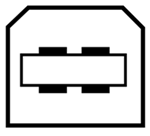
2 m (6.5 ft) USB Type B to Type A Cable Included
Thorlabs offers two platforms to drive our wide range of motion controllers: our Kinesis® software package or the legacy APT™ (Advanced Positioning Technology) software package. Either package can be used to control devices in the Kinesis family, which covers a wide range of motion controllers ranging from small, low-powered, single-channel drivers (such as the K-Cubes™ and T-Cubes™) to high-power, multi-channel, modular 19" rack nanopositioning systems (the APT Rack System).
The Kinesis Software features .NET controls which can be used by 3rd party developers working in the latest C#, Visual Basic, LabVIEW™, or any .NET compatible languages to create custom applications. Low-level DLL libraries are included for applications not expected to use the .NET framework. A Central Sequence Manager supports integration and synchronization of all Thorlabs motion control hardware.

Kinesis GUI Screen
APT GUI Screen
Our legacy APT System Software platform offers ActiveX-based controls which can be used by 3rd party developers working on C#, Visual Basic, LabVIEW™, or any Active-X compatible languages to create custom applications and includes a simulator mode to assist in developing custom applications without requiring hardware.
By providing these common software platforms, Thorlabs has ensured that users can easily mix and match any of the Kinesis and APT controllers in a single application, while only having to learn a single set of software tools. In this way, it is perfectly feasible to combine any of the controllers from single-axis to multi-axis systems and control all from a single, PC-based unified software interface.
The software packages allow two methods of usage: graphical user interface (GUI) utilities for direct interaction with and control of the controllers 'out of the box', and a set of programming interfaces that allow custom-integrated positioning and alignment solutions to be easily programmed in the development language of choice.
A range of video tutorials is available to help explain our APT system software. These tutorials provide an overview of the software and the APT Config utility. Additionally, a tutorial video is available to explain how to select simulator mode within the software, which allows the user to experiment with the software without a controller connected. Please select the APT Tutorials tab above to view these videos.
Software
Kinesis Version 1.14.47
The Kinesis Software Package, which includes a GUI for control of Thorlabs' Kinesis and APT™ system controllers.
Also Available:
- Communications Protocol
Software
APT Version 3.21.6
The APT Software Package, which includes a GUI for control of Thorlabs' APT™ and Kinesis system controllers.
Also Available:
- Communications Protocol
The APT video tutorials available here fall into two main groups - one group covers using the supplied APT utilities and the second group covers programming the APT System using a selection of different programming environments.
Disclaimer: The videos below were originally produced in Adobe Flash. Following the discontinuation of Flash after 2020, these tutorials were re-recorded for future use. The Flash Player controls still appear in the bottom of each video, but they are not functional.
Every APT controller is supplied with the utilities APTUser and APTConfig. APTUser provides a quick and easy way of interacting with the APT control hardware using intuitive graphical control panels. APTConfig is an 'off-line' utility that allows various system wide settings to be made such as pre-selecting mechanical stage types and associating them with specific motion controllers.
APT User Utility
The first video below gives an overview of using the APTUser Utility. The OptoDriver single channel controller products can be operated via their front panel controls in the absence of a control PC. The stored settings relating to the operation of these front panel controls can be changed using the APTUser utility. The second video illustrates this process.
APT Config Utility
There are various APT system-wide settings that can be made using the APT Config utility, including setting up a simulated hardware configuration and associating mechanical stages with specific motor drive channels. The first video presents a brief overview of the APT Config application. More details on creating a simulated hardware configuration and making stage associations are present in the next two videos.
APT Programming
The APT Software System is implemented as a collection of ActiveX Controls. ActiveX Controls are language-independant software modules that provide both a graphical user interface and a programming interface. There is an ActiveX Control type for each type of hardware unit, e.g. a Motor ActiveX Control covers operation with any type of APT motor controller (DC or stepper). Many Windows software development environments and languages directly support ActiveX Controls, and, once such a Control is embedded into a custom application, all of the functionality it contains is immediately available to the application for automated operation. The videos below illustrate the basics of using the APT ActiveX Controls with LabVIEW, Visual Basic, and Visual C++. Note that many other languages support ActiveX including LabWindows CVI, C++ Builder, VB.NET, C#.NET, Office VBA, Matlab, HPVEE etc. Although these environments are not covered specifically by the tutorial videos, many of the ideas shown will still be relevant to using these other languages.
Visual Basic
Part 1 illustrates how to get an APT ActiveX Control running within Visual Basic, and Part 2 goes on to show how to program a custom positioning sequence.
LabVIEW
Full Active support is provided by LabVIEW and the series of tutorial videos below illustrate the basic building blocks in creating a custom APT motion control sequence. We start by showing how to call up the Thorlabs-supplied online help during software development. Part 2 illustrates how to create an APT ActiveX Control. ActiveX Controls provide both Methods (i.e. Functions) and Properties (i.e. Value Settings). Parts 3 and 4 show how to create and wire up both the methods and properties exposed by an ActiveX Control. Finally, in Part 5, we pull everything together and show a completed LabVIEW example program that demonstrates a custom move sequence.
Part 1: Accessing Online Help
Part 2: Creating an ActiveX Control
Part 3: Create an ActiveX Method
Part 4: Create an ActiveX Property
Part 5: How to Start an ActiveX Control
The following tutorial videos illustrate alternative ways of creating Method and Property nodes:
Create an ActiveX Method (Alternative)
Create an ActiveX Property (Alternative)
Visual C++
Part 1 illustrates how to get an APT ActiveX Control running within Visual C++, and Part 2 goes on to show how to program a custom positioning sequence.
MATLAB
For assistance when using MATLAB and ActiveX controls with the Thorlabs APT positioners, click here.
To further assist programmers, a guide to programming the APT software in LabVIEW is also available here.
| Posted Comments: | |
chuanyuan Ding
(posted 2024-04-12 15:30:41.467) 1、LTS150C/M和LTS150/M的区别?
2、Labview编程的上位机是否通用两种型号? user
(posted 2024-02-19 13:12:25.197) I have bought a new LTS150C/M and I was trying to interface it with LabVIEW using the APT active node following your "User Guide to LabVIEW & APT" pdf. I cannot seem to be able to do anything other than retrieving its position. I enter the HWSerialNumber and the connection is extablished properly and that is it. When trying to do anything else like MoveHome or setting Velocity or Acceleration, it either gives an error. Is there any whole guide to all methods that I can use and how to use it? I would appreciate a quick response as this is very urgent. cstroud
(posted 2024-02-28 10:42:31.0) Thanks for reaching out, I'm sorry that you're having issues with APT. We have contacted you directly to troubleshoot this issue. Eminhan Ozil
(posted 2024-02-01 13:42:19.787) Hello, what is the minimum reliable constant travel speed in um/s? It will be in horizontal orientation with a light load. Ideally, I am looking for a motorized linear stage with travel distance >100mm and minimum constant travel speed of ~100um/sec (if it can go lower ~5um/sec, even better). Would you recommend this stage or another one? Thanks a lot! Dale Lossing
(posted 2023-09-13 15:54:34.9) Seeking a replacement for the PIJ30-24-01 power adapter included with the LTS150C stage. One of ours came up missing. do'neill
(posted 2023-09-15 05:56:39.0) Response from Daniel at Thorlabs. I will reach out to you directly to discuss this with you. Rui Almeida
(posted 2023-06-13 14:35:00.32) What is the relation between encoder steps and the position in mm of the stage? do'neill
(posted 2023-06-15 09:55:12.0) Response from Daniel at Thorlabs. This conversion for all our stages can be found in our communication protocol that can be found here:
https://www.thorlabs.com/Software/Motion%20Control/APT_Communications_Protocol.pdf
For the LTS150C there are 409600 microsteps per mm and I will reach out to you to discuss this further Sean Long
(posted 2023-01-10 14:39:12.053) Just wonder if this device can support following application through Labview programm:
1) Continuously run 256 step with equal step at 0.4mm.
2) Each step needs to run at different speed ranging from 0.5~20mm/s.
3) Do you have a similar Labview example for that?
4) How to set Jog profile with different accelerations? JReeder
(posted 2023-01-12 06:18:35.0) Thank you for your enquiry. You can indeed perform this sort of sequence by writing your own custom LabVIEW script. Some of the specific commands that you need would be 'SetJogStepSize' for setting the joy step size and 'SetJogVelocityParams' for setting the velocity and acceleration of the movement. Our .NET API can be found in C:\Program Files\Thorlabs\Kinesis once our Kinesis software has been downloaded. I have also reached out to you to provide a simple example of using the LTS stage in LabVIEW. It is worth noting that any 2-phase stepper motor will become unstable at low velocities such as 0.5 mm/s. As you reduce the velocity of the stage, the movement may seem to microscopically ‘stop-start’ depending on the application’s requirements. This is due to the time between motor phases increasing to produce this ultra-low velocity which consequently leads to the motor stalling if there are torque hotspots, where say the pitch of the leadscrew is not perfect. This will vary between each model as at this slow speed any irregularities in the stage are emphasized. This would also be heavily dependent upon the load employed. Zhi Huang
(posted 2023-01-10 10:37:20.233) For LabVIEW through Kinesis functions, in method "SetJogMoveParams (decimal velocity, acceleration)", what are the units for the V and a? mm/sec, mm/s^2 or step number? do'neill
(posted 2023-01-11 05:36:57.0) Response for Daniel at Thorlabs: Thank you for your enquiry. For most of the commands in this format there are two commands, e.g. SetJogParams that uses real world units (mm, mm/s, etc) and SetJogParams_DeviceUnit which work in integer device units. More information on this can be found in the .Net API included in the Kinesis download. I will reach out to you to discuss this further. Qi Lu
(posted 2022-12-10 13:42:04.89) Hello, I'd like to control the LTS150/M from position 100 mm to 105 mm based on C#, and I want this process takes exactly 5 seconds, which functions should I use? I did not find any functions related to time control or speed control in the provided C# SDK. do'neill
(posted 2023-01-11 06:00:12.0) Response from Daniel at Thorlabs. The command you will need to set this up is SetVelocityParams() Using this you will be able to set the acceleration and the maximum velocity. The default velocity profile is a trapezium so you should be able to work out a velocity and acceleration that theoretically moves the stage 5mm in 5s. The only possible issue is that the LTS150 has a velocity stability of ±1mm/s at maximum velocity and would need to be tested at lower velocities. Someone from your local technical support team will reach out to you to further discuss your application Zikun Cao
(posted 2022-11-22 16:15:10.147) Hello. I have a question about the move sequence in the APT software. I have two moving stage in hand, and I mount them together using a Z-Axis Bracket. Now I want to control the motion of these two stage in the move sequence so that they can move at the same time. Can I write a single csv file in the move sequence tab in the APT software to achieve this? DJayasuriya
(posted 2022-11-25 03:41:00.0) Thank you for your inquiry. Yes you would be able to load a cvs file so to get the stages to move at the same time. We have got in touch with you directly to discuss your application. Wolfgang Stumpf
(posted 2022-10-06 10:48:13.727) Sehr geehrte Damen und Herren,
wir möchten den LTS150/M in einem industriellen System einsetzen. Dazu würden wir gerne eine andere 24 V Spannungsquelle verwenden, welche mindestens 20 A Konstantstrom abdeckt. Wären damit die Anforderungen an Stromspitzen des LTS150/M Motors erfüllt oder würden Sie (ggf aus anderen Gründen, Restwelligkeit, Rauschen, etc.) zur Verwendung des mitgelieferten Thorlabs Netzteils raten?
Mit freundlichen Grüssen,
Wolfgang Stumpf cwright
(posted 2022-10-11 05:53:55.0) Reponse from Charles at Thorlabs: Thank you for your query. The LTS150/M will draw a peak power of 25W at 24V so a 20A supply more than meets the current requirements. A member of German technical support will reach out to you to discuss this. Jörn Güldenhaupt
(posted 2021-08-11 02:06:00.443) Hello,
i have a question reagarding the programming (C# .NET) of the LTS150/M stage: Is there a Command/Method to find out the difference between the real homing position (0 mm) and the offset (x mm) after a homing of the stage was done? I want to know if a homing was necessary and if any steps were lost - this info should be used for quality control reasons.
Best regards
Jörn Güldenhaupt DJayasuriya
(posted 2021-09-03 04:48:41.0) Thank you for your inquiry. There is no straightforward method but we will get in touch with you directly to resolve your issue. Susan Lindecrantz
(posted 2021-02-02 10:41:41.857) When I start up the LTS150 with MATLAB using .NET I can connect to it and its responding. However, after a while I loose contact (while my code does something else with a camera). The unit is not responding to a new position, via the function calling device.MoveTo(new_pos,timeout_val). Sometimes it does and sometimes it doesn't. I am not disconnecting the device in-between. Should I keep reconnecting to the device every time I loose contact? How should I write that move function so it reassume connection and move to new position without homing it? DJayasuriya
(posted 2021-02-04 09:03:44.0) Thank you for your enquiry. I will get in touch with you directly to resolve your issue. Andrew Barrette
(posted 2020-10-31 22:57:02.61) I would like to buy the LTS150, but am having trouble figuring out which controller goes with it. The page says that this motor uses a "T-Cube", and that would be nice since already have a hub it could go on, however I only see T-Cubes for temperature and LED control. The only motion control cubes I can find are K-Cubes. cwright
(posted 2020-11-02 05:54:56.0) Response from Charles at Thorlabs: Hello Andrew and thank you for your query. This stage actually has an integrated controller and does not need a T-cube or other external controller. The reference I believe you are referring to on the Overview tab is just elaborating on the flexibility of the software. The LTS can be connected directly to a PC using a USB lead. Elli King
(posted 2019-09-26 21:20:42.307) I've been using a LTS150/M stage for roughly one year, and I can hear the motor labouring as the stage moves. The weight limit isn't being exceeded. Is there some maintenance we need to perform in terms of cleaning or greasing the shaft? cwright
(posted 2019-09-30 08:11:04.0) Hello Elli. The lead screw and bearings are not easily accessible without partial disassembly of the stage. To ensure the correct procedure is followed and to preserve it's warranty we would recommend LTS stages be returned to us for assessment and maintenance. I will contact you directly about this. Arvin Mossadegh Pour
(posted 2019-04-24 10:32:15.093) Do you have ready to use LabVIEW VI for LTS150/M ? AManickavasagam
(posted 2019-04-25 09:16:41.0) Response from Arunthathi at Thorlabs: Unfortunately, we do not have a VI specific for LTS150 however, here is the link to all the example VIs we have https://www.thorlabs.com/newgrouppage9.cfm?objectgroup_id=12675&tabname=Example%20VIs greg.bredthauer
(posted 2019-01-22 14:37:34.387) Hello, I'm using the LTS150 in an image sensor test setup. The LEDs inside the LTS150 are a major source of extraneous light/signal. Is there a way to disable them?
Thanks,
-Greg rmiron
(posted 2019-01-23 11:02:30.0) Response from Radu at Thorlabs: Hello, Greg. The LEDs of some of our motion controllers can be disabled using the SetLEDSwitches method from Kinesis' .NET API. Unfortunately, LTS's firmware does not support this feature. Thanks to you bringing the issue to our attention, we will look into amending the firmware accordingly. For now, I recommend that you use black masking tape, such as T743-1.0. mohammad.azizian
(posted 2018-07-19 17:39:36.67) Hi,
We have this product combined with LTS300/M, and I am controlling them with APT software. I have two questions:
1) how can I translate the APT positions into cm/mm
2) where can I download the labview VIs for these?
Thanks in advance AManickavasagam
(posted 2018-07-23 10:35:14.0) Response form Arunthathi at Thorlabs: Thanks for your query. Unfortunately with APT you are unable to swtich from mm to cm. However, if you control the stages with Kinesis it does allow you to convert between cm/mm.
Regarding the LabView APIs I have contacted you directly to provide guidelines and link to download such sample VIs. roberto.ocana
(posted 2018-05-28 11:11:03.363) Dear Thorlabs,
I just wanted to know if sycronization of two travel stages is possible, for example. to perform a circular trajectory with a X-Y configuration. I am looking forward to your feedback.
Best regards. bhallewell
(posted 2018-06-05 05:34:26.0) Response from Ben at Thorlabs: Thank you for your question. Our Motorised Hardware & Motion Control software does not currently support synchronised, interpolated motion required for circular motion profiles. I have logged your feedback in our Internal Products Forum as a future product idea. chaos89
(posted 2018-03-28 02:52:34.8) Dear Thorlabs.
I am developing the application software for LTS150 with Visual stuido c++ language.
I cannot understand how i do program the interface with LTS150 from the manual document of APT Commnuication protocol.
Can I get the example source for interface with LTS 150 ?
I'm looking forward to your kind response
Thanks. bhallewell
(posted 2018-04-05 06:39:18.0) Response from Ben at Thorlabs: Thank you for your feedback. You can find our Kinesis support documentation & examples in the following link.
https://www.thorlabs.com/newgrouppage9.cfm?objectgroup_id=10285
I will contact you to discuss this. wenzel.jakob
(posted 2017-12-09 15:27:42.28) I'm curious how the provided calibration files could be used if the stage is driven via APT commands from a Linux machine. Are these files in an easily readable format (e.g. position -> deviation in ASCII), or can Thorlabs provide a specifications of their contents? bhallewell
(posted 2017-12-28 10:00:38.0) Response from Ben at Thorlabs: I will contact you directly to discuss this & provide an example calibration file. rodriguez257
(posted 2017-06-26 09:50:01.337) I have been using your LTS-150 and am very satisfied with it. For my application, it would be very beneficial to know what load the motion stage is seeing along its axis of movement. I was wondering, is there any force feedback data maybe for preventing overloading the motor that I can access?
Thanks,
Nick bwood
(posted 2017-07-03 10:37:19.0) Response from Ben at Thorlabs: Thank you for your feedback. It is difficult to give an absolute force spec for the stage, as it is dependant on the nature of the force (e.g. is it axial or off-axis). However, the vertical load capacity gives a good estimate of the force it can act against. This gives a force of ~40N. tom.dunn
(posted 2017-05-25 17:04:34.233) We are regular users of your LTS-150M product and have purchased many over the last 6 years. I just received a brand new one today. I completely removed the old ThorLabs software from my computer, rebooted and loaded the latest download from your website. I used APT Config to download the latest firmware into my new unit. When I run APT User it recognizes the stage as a HS unit, but the max speed is limited to 20mm/S. How do I get it to recognize the stage is capable of the max speed of 50mm/S? bwood
(posted 2017-05-31 05:57:31.0) Response from Ben at Thorlabs: Thank you for your feedback. While the default maximum velocity is 20mm/s, you can change this in the settings of both Kinesis and APT. I will contact you directly to help troubleshoot this in case there are any further issues. thomas.hingant
(posted 2017-03-21 08:31:17.34) Dear customer support.
I have bought two LTS150/M to run them with windows XP but I have just come to realized there are no driver available online under windows 7.
Do you have a solution for this?
I would like to run the motors with VBA so I would just need the drivers for interfacing the stages. Thank you! bwood
(posted 2017-03-21 06:44:30.0) Response from Ben at Thorlabs: Thank you for your feedback. We can offer a legacy version of APT, which should include the files and drivers necessary to run the stages on a Windows XP machine. Please note, as it is a legacy version of the software, we cannot guarantee support of new stages. I will be in contact with you directly, to send you this version of APT. coen.timmermans
(posted 2017-03-06 02:52:04.84) Dear customer support, I want to use the LTS150/M to make a movement of 130mm. In the specs the absolute on-axis accuracy is described as 20um and the calibrated on-axis accuracy is even 5um. a better indication is of course the max percentage accuracy which is 0,13%. I made the following calculation: 130mm/100*0.13% = 0,169mm. Can you tell me which number for accuracy I can use because the maximum 20um and the calculated 169um has a lot of difference?
Thank you! Coen Timmermans bwood
(posted 2017-03-07 08:15:23.0) Response from Ben at Thorlabs: Thank you for your question. The maximum percentage accuracy is designed to represent the change of the accuracy with longer moves. With this, and the notes on the "Specs" tab, in mind, we would suggest taking the figure you calculated as the lowest accuracy, and so the highest error, which can be expected with a 130mm move. sfm0122
(posted 2016-10-07 02:34:23.67) Hi there,
I have a problem when using Labview and APT software to control the LTS150m. There is a red light blinking inside the travel stage. The situation is, at the beginning, when the computer is not turned on, the travel stage can move manually. However, after I turn on the software and try to control the stage with APT or Labview, the stage move extremely slow ( lower than 1mm/s). I have checked the program and the same program works for the LTS300. I was wondering if the problem lies in the control chip. Could you give me some advice? bhallewell
(posted 2016-10-07 06:40:28.0) Response from Ben at Thorlabs: Thank you for reaching out to us for assistance. I believe that this may linked to how the stage is configured within the software package you are using. I'm going to contact you directly to help get your stage up & running. hishihara
(posted 2016-06-03 17:04:44.393) Dear customer support,
I have several questions. I want make motorized x-y moving stage using two LTS150. We purchased one LTS150 stage few years ago. When I control x-y axis from PC, do I need to purchase stepper motor controller? Whats parts do I need to Purchase? Also Do you have academic discount? Could you send me a list and quotation?
Thank you.
Hidetaka Ishihara. msoulby
(posted 2016-06-06 07:02:59.0) Response from Mike at Thorlabs: The LTS150 stage has an integrated stepper motor controller so it does not require a separate controller to operate. You simply plug in the power supply and USB cable into the stage and you will be able to operate the stage. Your local Thorlabs office will contact you shortly with a quotation in your local currency, please see the following page for more details on our current discount policy http://www.thorlabs.de/discountPolicy.cfm hungch
(posted 2016-03-07 15:01:16.01) Hello, I would like to ask the definition of the horizontal load and vertical load.
I am planing to build up a XYZ motion stages. As a result, the loading capacity is my concern.
Thank you msoulby
(posted 2016-03-09 04:26:30.0) Response from Mike at Thorlabs: The load capacity is the maximum load that can realistically be actuated by the stage over its lifetime and also the load at which the specifications can be maintained. This is typically less than the limit to what the stage can actually move: if the stage is used above this limit it can significantly reduce the lifetime of the stage. Load capacity can be defined in a number of directions; horizontally, vertically and at a set distance from the main load bearing axis. Unless otherwise stated Thorlabs specifies its load capacities at the top plate and any moment arm calculations must be taken into account if the load is at a distance from the top plate. pratik.choudhary
(posted 2016-02-09 14:12:04.15) hallo,
I am Pratik Choudhary working Institute for Microstructures in KIT. I want to buy motorized stage controller and I have following queries so please help me about the technical details that the product offers.
I want the stage to accommodate a wafer of 4 inches and I want to analyse my wafer automatically in X,Y & Z direction with a travel range at least 4 inches in X & Y direction.
And please also let me know all the features like minimum step size in X&Y axes and also controller options so that I can control according to my needs. And whether the controller work with any particular software or we can program it using programming language.
So please respond to my following queries.
Regards
Pratik Choudhary
Student Research Assistant KIT. cevered
(posted 2016-02-12 04:53:52.0) Thanks for posting your questions using our web feedback tool. The LTS150(/M) stages have a travel range of 5.9 inches (150mm). The minimum achievable incremental movement (also known as the minimum step size) is 100nm. You can convert three individual LTS150(/M) stages into an XYZ stage using the LTSP1(/M) and LTSP2(/M) adapter plate and bracket. These stages utilise an integrated controller with remote USB control, so a separate control unit would not be necessary. As outlined on the above 'Motion Control Software' tab, custom applications can be developed using any ActiveX compatible language such as C#, Visual Basic and LabVIEW. You can choose between our legacy APT motion control software or the Kinesis Software to control movement of the axes. Kinesis also features new .NET controls which can be used by 3rd party developers working in any .NET compatible language. Both pieces of software are free to download from the Motion control tab and here: https://www.thorlabs.de/software_pages/ViewSoftwarePage.cfm?Code=Motion_Control. adam.wyatt
(posted 2016-01-14 23:24:57.917) The stage settings in the APT software no longer seem to be correct, so that the stage is not moving the correct amount - could you please provide the exact specifications for the stage (e.g. thread pitch, gear ratio etc.) msoulby
(posted 2016-01-15 03:16:31.0) Response from Mike at Thorlabs: You will need to ensure that the APT configuration has not been changed for that particular serial number. We would recommend checking the APT configuration utility to ensure that the correct stage is set, this should be set to “HS LTS150 150mm Stage”. The individual settings you mentioned are as follows, Pitch = 1.0, Gearbox Ratio = 1, Steps per Rev = 200 xgsun
(posted 2015-10-27 06:48:34.447) I am using a LTS150with Labview. I need move the position and change the speed during the movement.. I use the command "SetVelparams" to cahnge and "GetVelParams" to confirm. though the number came back is changed, but the actual speed doesn't change. besembeson
(posted 2015-10-30 11:34:41.0) Response from Bweh at Thorlabs USA: Unfortunately this option will not be available due to hardware restrictions on the devices themselves. It is not possible to change the velocity whilst moving. This is due to the size of the message buffers and the communication protocols we use. Discrete stepping at different velocities is currently the best we can offer. btywoniuk
(posted 2015-06-17 00:32:14.34) Hi,
Do you provide Python libraries support for LTS150? rcapehorn
(posted 2015-06-18 10:53:42.0) Response from Rob at Thorlabs: At this time we do not have any specific documentation for using our APT software in Python. However the APT server uses an ActiveX Server/client model, if you are able to import ActiveX control objects into you Python application then you should be able to use APT in python (which I believe you can). The ActiveX control object for motors is called MGMotor.ocx and is located in the Thorlabs installation directly in the APT server folder. To start the control you will need to pass the serial number of the controller using the HWSerialNum ActiveX property followed by the ActiveX method StartCtrl. This is the very basic outline of what needs to happen to run the APT software in a third party program. However a full list of the APT server methods can be found in the start menu folder for Thorlabs APT in here there is a help file called APT server help which contains a list of all the ActiveX methods, events and properties for your information.
Alternatively you can set the USB port up as a COM port and use direct serial communication with the device. For more information on serial communication with APT, please download the Communication Protocol document found here - http://www.thorlabs.de/software_pages/ViewSoftwarePage.cfm?Code=APT. chaymae.lourhzal
(posted 2015-06-12 04:14:05.823) hello. My LTS150 stage have a problem in translation: it translates till 50 mm and makes noise and can't move along (the axis can't turn and is blocked). I don't know if it's due to a homing problem but probably it's mechanical. Is it necessary to return it back to the factory ? Do you have a manual of such mechanical problems in order to have an idea ? bwood
(posted 2015-06-15 09:08:14.0) Response from Ben at Thorlabs: I'm sorry to hear about the issues you are having with your LTS150. I will be contacting you directly for more information on the issue and your setup, and with this information I will be able to diagnose and resolve your problem. po_sun
(posted 2014-11-15 14:35:16.54) My application does not care about the accuracy along axis direction (x direction), but requires a good accuracy along z direction (up&down direction). The load weight will be less than 500g. The z-direction accuracy should less than 2um. Can this model fit my application? If not, any recommendation?
Thanks msoulby
(posted 2014-11-18 09:26:08.0) Response from Mike at Thorlabs: The absolute on-axis accuracy of the LTS stages is 20µm and the maximum percentage accuracy is 0.13%. We do not currently offer a stage with <2um accuracy but we would recommend our DDS300/M stage which has an absolute on-axis accuracy of ±7.5µm. The DDS300/M stage does have an optical encoder with a resolution of 100nm which provides positional feedback to the controller and it is possible to achieve a bidirectional repeatability of 0.25um. micah.hodgins
(posted 2014-09-29 16:05:40.58) Hello,
I see that the max load when horizontally placed is 15kg but I would like to know what is the max torque (N*m) allowed for the carriage??
I'm interested in mounting a sensor on a cantilever arm and need to know the max moment the carriage can withstand.
Thanks, Micah msoulby
(posted 2014-10-01 03:36:07.0) Response from Mike at Thorlabs: At this time we only have on-axis load capacity measurements. If your load is only a 3-4kg and the moment arm is not very long then this will be fine: a larger load can be counter balanced to reduce the overall torque. I have contacted you directly to find out more about the load you wish to mount onto the stage. andres.varon
(posted 2014-04-28 10:40:55.343) What is the maximal load that the stage can handle when installed along the vertical direction? To hold a Position is the Motor all time ON? How good is a possition Held when the stage is Hold at a given point? Can I expect some "microvibrations"? Of what Amplitude? Thank you for your feedback msoulby
(posted 2014-04-29 03:27:59.0) Response from Mike at Thorlabs: The maximum vertical load the LTS stage can handle is 4kg. As the stage uses a stepper motor then even at rest there will still need to be a holding current supplied to the stage to maintain its position. The motor has a holding torque of 20Ncm so providing this is not exceeded by overloading then the stage should maintain a steady position. adam.wyatt
(posted 2014-03-05 17:22:47.24) The APT control software is not compatible with Matlab x64. Peiyu.Chen
(posted 2014-03-04 13:06:19.043) I am using Matlab 2011a (64bit win 7) to control LTS300. I registered MG17Motor.ocx by using !regsrv32 several times but the Matlab activeX control list never show its ProgID. Is it because of the 64bit-version Matlab? Could you please provide me some technical suggestions? msoulby
(posted 2014-03-06 09:57:25.0) Response from Mike at Thorlabs: We are looking to have a beta version of the 64bit DLL for APT working in the next couple of weeks. After which point we will release it to customers on request. We will contact you again when this is ready. tcohen
(posted 2012-10-04 13:02:00.0) Response from Tim at Thorlabs: The list of methods can be found in the APT Server Help that is installed with APT in the following directory: Thorlabs>APT>Help>APT Server Help. garguell
(posted 2012-10-04 12:15:18.0) Hello,
I am trying to program the stage in Labview and was wondering if there was a reference list of the Methods we can use. It would be nice to have a description of what each Method does and how to use each one. If there isn't, I think it would be helpful if there was.
Thank you! bdada
(posted 2012-01-27 14:04:00.0) Response from Buki at Thorlabs:
Thank you for using our online feedback tool. For the LTS300/M, we specify the pitch to be 0.022° and the yaw to be 0.06°, which defines how much the moving world shifts as the stage translates. Please see below for a brief explanation on the pitch and yaw. Please contact TechSupport@thorlabs.com if you have additional questions.
Pitch
The stage was moved over its full travel and an angular RLI measurement was taken in the pitch axis at 20 or 10 equidistant points along the travel, dependent on the stages travel. This was repeated 10 times and the maximum discrepancy between minimum and maximum value taken.
Yaw
The stage was moved over its full travel and an angular RLI measurement was taken in the yaw axis at 20 or 10 equidistant points along the travel, dependent on the stages travel. This was repeated 10 times and the maximum value taken. khmadsen
(posted 2012-01-23 14:15:52.0) I need to place a pinhole on the LTS300/M and a light beam is to go through the pinhole for all positions of the stage. How much will the center of the pinhole move in the plane perpendicular to the travelling direction?
Regards, Kristian khoe
(posted 2012-01-13 05:08:22.0) What is the accuracy in the plane perpendicular to the travelling direction?
Regards, Kristian Thorlabs
(posted 2010-11-04 09:47:24.0) Response from Javier at Thorlabs to bbel10: the limiting factor for increasing the speed of the LTS stage is the current that the controller can source. We are currently working on the design of a new stage with a travel range of 280 mm and a maximum speed of 200 mm/s. I will contact you directly with more details. bbell10
(posted 2010-11-03 11:29:46.0) Can the leadscrew be changed in these stages so that a faster translation rate can be acheived? If I recall it is currently 15mm/sec. I need a minimum of ~25mm/sec travel or higher. Thorlabs
(posted 2010-10-14 15:52:35.0) Response from Javier at Thorlabs to John Garnier: the controller of the LTS stages is built in the assembly, so there is no need to purchase an external driver. You can also connect it directly to your PC. The NR360S/M does require an external controller. We recommend using the BSC101 (http://www.thorlabs.com/NewGroupPage9.cfm?ObjectGroup_ID=1064&pn=NR360S). john.garnier
(posted 2010-10-14 12:25:47.0) LTS300/M and NR360S/M
Do these stages have build in power supply motion controller dfro direct interface to PC ?
or do I need to add in intermediate motion controller (e.g. 1,2 or 3 unit aptTM Stepper Motor Controller) to complete the system set-up?
Its clear that the unit aptTM Stepper Motor Controller is needed with other motorized translation stages such as the NRT100/M
Please advise: John
office: 208 526 9388 It may be faster to send your e-mail with your phone contact john.garnier@inl.gov user
(posted 2010-09-29 07:46:08.0) A reply from Oli at Thorlabs to William: Unfortunately this would need to come back to Thorlabs for repair of the limit switch, I will contact you directly to go through some troubleshooting to ensure the limit switch is at fault and set up a return. william.doherty
(posted 2010-09-28 08:40:35.0) HI,
Just came across a problem with the limit switches. On homing, the drive stage hits the end of the track but keeps trying to drive, suggesting the limit switches are not working. Can these be reset or is it a factory job?
Regards,
William user
(posted 2010-08-30 21:35:30.0) A reply from Jens at Thorlabs: after installing the APT software click on Windows Start - All Programsand select APT - Help - APT Server Help. This will give you e.g. a detailed description for each method. Besides that you can look at the online tutorials at
http://www.thorlabs.com/tutorials/Intro.cfm
and
http://www.thorlabs.com/images/TabImages/GuideToLabVIEWandAPT.pdf p.modard
(posted 2010-08-30 16:22:41.0) Hello. Can you please tell me where I can find a document which explains the LabView commands to control the LTS? Thanks. Philippe Thorlabs
(posted 2010-08-26 09:58:12.0) Response from Javier at Thorlabs to rbjaculbia: Thank you for your feedback. We will release a variable optical delay line stage which may be more suitable for your application than one of the LTS stages within the next few weeks. It features a travel range of 200 mm, 500 mm/s maximum speed, and it can achieve a max. optical delay of 667 ps. We can arrange for you to receive a prototype unit so that you can test it in your experiment. I will contact you directly with more details. rbjaculbia
(posted 2010-08-25 21:33:45.0) Hello. We are looking to use the LTS300 for a delay line. However my adviser is asking if there are other research laboratories who use this stage for their experiments. Would it be possible if you could give us a list of customers who use your product so that we can be assured that it would work with our system? Thank you klee
(posted 2009-09-21 18:08:31.0) A response from Ken at Thorlabs to martini: We are currently contacting customers to check if they would be willing to share their experience. We will send you details via email. And per our phone conversation last week, we can offer a loan unit at any time so you can directly compare the two systems. martini
(posted 2009-09-14 13:56:24.0) Hi. We are setting up an ultrafast laser system and need a translation stage. We found that your product is very economical, compared to the most commonly used Newport translation stage found in most labs. Do you have a list of user that are currently using your product? Id like to get some feedback from first hand users, and I would also appreciate any comment you might have about this.
Ignacio jens
(posted 2009-06-29 11:09:51.0) A reply from Jens at Thorlabs: I have just send the manual to you via email, the file will be update on the web page within the next hours. Thanks for notifying us. thomasce2
(posted 2009-06-29 10:38:44.0) Hi.
Manuals refuse to download for the LTS150 and LTS300 stages (English and Metric). Interestingly the icon shows a Word document but the download is for a PDF file. Anyhow, "page not found" error appears for all the LTS manuals
(Windows XP and IE8).
regards, tommy thomas
(I was trying to get the LTS300 manual and then tried all the others) |
Motorized Linear Translation Stages
Thorlabs' motorized linear translation stages are offered in a range of maximum travel distances, from a stage with 20 µm of piezo translation to our 600 mm direct drive stage. Many of these stages can be assembled in multi-axis configurations, providing XY or XYZ translation. For fiber coupling applications, please see our multi-axis stages, which offer finer adjustment than our standard motorized translation stages. In addition to motorized linear translation stages, we offer motorized rotation stages and goniometers. We also offer manual translation stages.
Piezo Stages
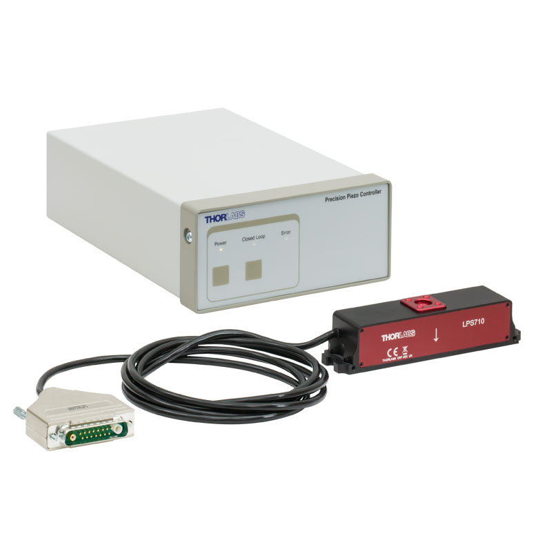
These stages incorporate piezoelectric elements in a variety of drive mechanisms. ORIC® stages incorporate piezo inertia drives that use "stick-slip" friction properties to obtain extended travel ranges. Our Nanoflex™ translation stages use standard piezo chips along with manual actuators. Elliptec® stages use resonant piezo motors to push and pull the moving platform through resonant elliptical motion. Our LPS710E z-axis stage features a mechanically amplified piezo design and includes a matched controller.
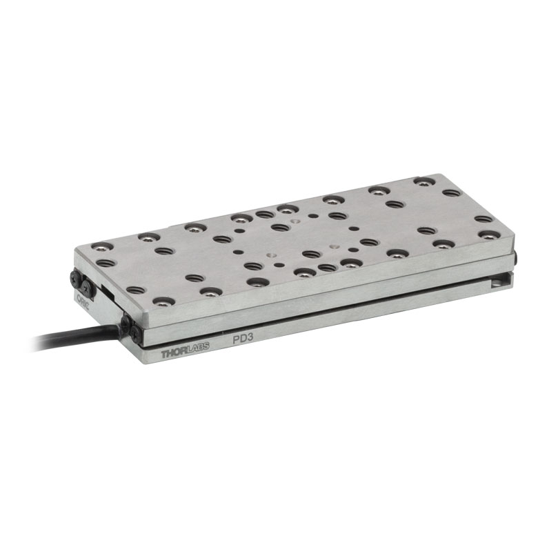
| Piezoelectric Stages | ||||
|---|---|---|---|---|
| Product Family | ORIC® PDXZ1 Closed-Loop 4.5 mm Vertical Stage |
ORIC® PD2 Open-Loop 5 mm Stage |
ORIC® PDX2 Closed-Loop 5 mm Stage |
|
| Click Photo to Enlarge |
 |
 |
 |
|
| Travel | 4.5 mm | 5 mm | ||
| Speed | 1 mm/s (Typ.)a | 10 mm/s (Typ. Max)b | 8 mm/s (Typ.)c | |
| Drive Type | Piezoelectric Inertia Drive | |||
| Possible Axis Configurations | Z | X, XY, XYZ | ||
| Mounting Surface Size |
45.0 mm x 42.0 mm | 13 mm x 13 mm | ||
| Additional Details | ||||
| Piezoelectric Stages | |||||
|---|---|---|---|---|---|
| Product Family | ORIC® PD1 Open-Loop 20 mm Stage |
ORIC® PD1D Open-Loop 20 mm Monolithic XY Stage |
ORIC® PDX1 Closed-Loop 20 mm Stage |
ORIC® PD3 Open-Loop 50 mm Stage |
|
| Click Photo to Enlarge |
 |
 |
 |
 |
|
| Travel | 20 mm | 50 mm | |||
| Speed | 3 mm/s (Typ. Max)a | 20 mm/s (Typ. Max)b | 10 mm/sc | ||
| Drive Type | Piezoelectric Inertia Drive | ||||
| Possible Axis Configurations | X, XY, XYZ | XY, XYZ | X, XY, XYZ | X, XY, XYZ | |
| Mounting Surface Size |
30 mm x 30 mm | 80 mm x 30 mm | |||
| Additional Details | |||||
| Piezoelectric Stages | ||||||
|---|---|---|---|---|---|---|
| Product Family | Nanoflex™ 20 µm Stage with 5 mm Actuator |
Nanoflex™ 25 µm Stage with 1.5 mm Actuator |
Elliptec® 28 mm Stage | Elliptec® 60 mm Stage | LPS710E 1.1 mm Vertical Stage | |
| Click Photo to Enlarge |
 |
 |
 |
 |
 |
|
| Travel | 20 µm + 5 mm Manual | 25 µm + 1.5 mm Manual | 28 mm | 60.0 mm | 1.1 mm | |
| Maximum Velocity | - | 180 mm/s | 90 mm/s | - | ||
| Drive Type | Piezo with Manual Actuator | Resonant Piezoelectric Motor | Amplified Piezo | |||
| Possible Axis Configurations | X, XY, XYZ | X | Z | |||
| Mounting Surface Size | 75 mm x 75 mm | 30 mm x 30 mm | 15 mm x 15 mm | 21 mm x 21 mm | ||
| Additional Details | ||||||
Stepper Motor Stages
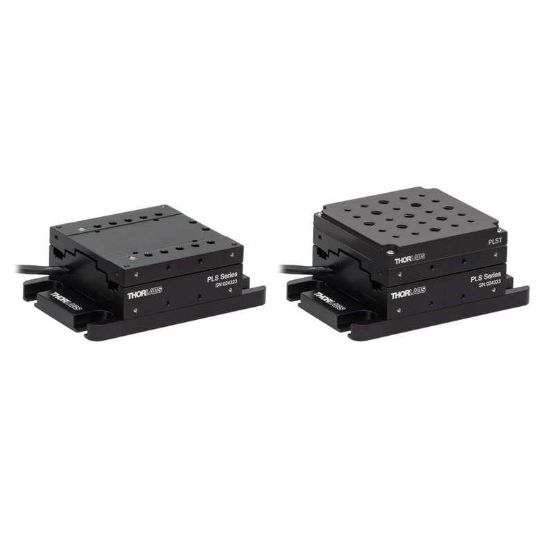
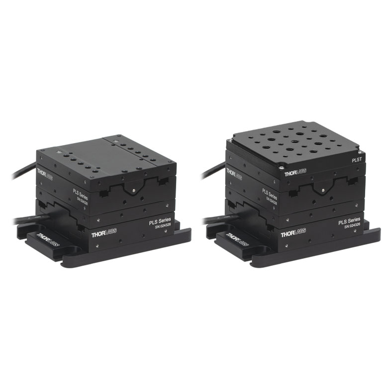
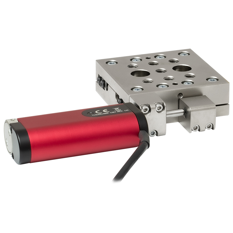
These translation stages feature removable or integrated stepper motors and long travel ranges up to 300 mm. Many of these stages either have integrated multi-axis capability (PLSXY) or can be assembled into multi-axis configurations (PLSX, LNR Series, NRT Series, and LTS Series stages). The MLJ150 stage also offers high load capacity vertical translation.
| Stepper Motor Stages | |||||
|---|---|---|---|---|---|
| Product Family | PLSX with and without PLST(/M) Top Plate 1" Stage |
PLSXY with and without PLST(/M) Top Plate 1" Stage |
LNR Series 25 mm Stage |
LNR Series 50 mm Stage |
|
| Click Photo to Enlarge |
 |
 |
 |
 |
|
| Travel | 1" | 25 mm | 50 mm | ||
| Maximum Velocity | 7.0 mm/s | 2.0 mm/s | 50 mm/s | ||
| Possible Axis Configurations |
X, XY | X, XY, XYZ | X, XY, XYZ | ||
| Mounting Surface Size |
3" x 3" | 60 mm x 60 mm | 100 mm x 100 mm | ||
| Additional Details | |||||
| Stepper Motor Stages | ||||||
|---|---|---|---|---|---|---|
| Product Family | NRT Series 100 mm Stage |
NRT Series 150 mm Stage |
LTS Series 150 mm Stage |
LTS Series 300 mm Stage |
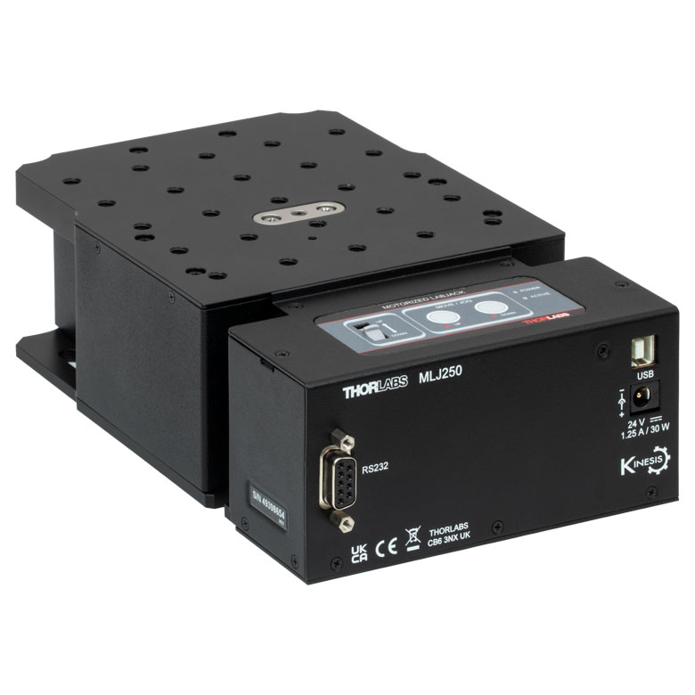
MLJ250 50 mm Vertical Stage |
|
| Click Photo to Enlarge |
 |
 |
 |
 |
 |
|
| Travel | 100 mm | 150 mm | 150 mm | 300 mm | 50 mm | |
| Maximum Velocity | 30 mm/s | 50 mm/s | 3.0 mm/s | |||
| Possible Axis Configurations |
X, XY, XYZ | X, XY, XYZ | Z | |||
| Mounting Surface Size |
84 mm x 84 mm | 100 mm x 90 mm | 148 mm x 131 mm | |||
| Additional Details | ||||||
DC Servo Motor Stages
Thorlabs offers linear translation stages with removable or integrated DC servo motors. These stages feature low profiles and many can be assembled in multi-axis configurations.
| DC Servo Motor Stages | ||||
|---|---|---|---|---|
| Product Family | MT Series 12 mm Stages |
PT Series 25 mm Stages |
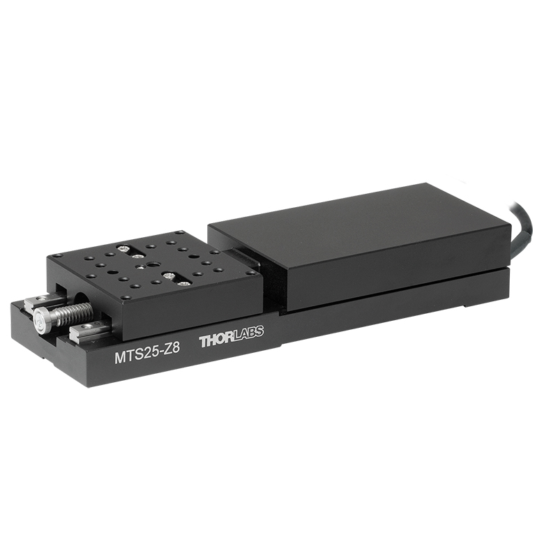
MTS Series 25 mm Stage |
MTS Series 50 mm Stage |
| Click Photo to Enlarge |
 |
 |
 |
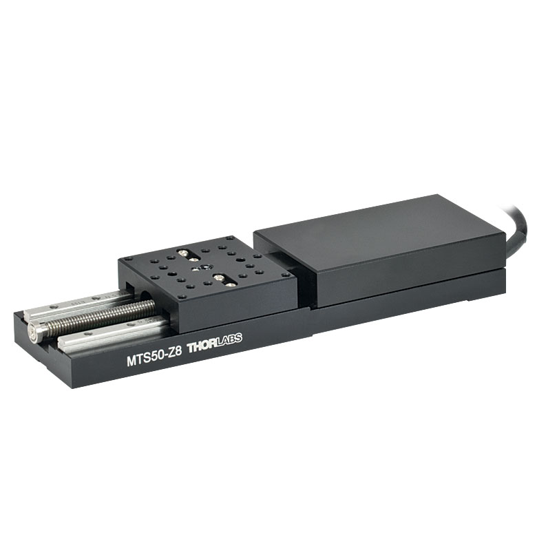 |
| Travel | 12 mm | 25 mm | 25 mm | 50 mm |
| Maximum Velocity | 2.6 mm/s | 2.4 mm/s | ||
| Possible Axis Configurations | X, XY, XYZ | X, XY, XYZ | ||
| Mounting Surface Size |
61 mm x 61 mm | 101.6 mm x 76.2 mm | 43 mm x 43 mm | |
| Additional Details | ||||
| DC Servo Motor Stages | ||||
|---|---|---|---|---|
| Product Family | M30 Series 30 mm Stage |
M30 Series 30 mm Monolithic XY Stage |
M150 Series 150 mm XY Stage |
KVS30 30 mm Vertical Stage |
| Click Photo to Enlarge |
 |
 |
 |
 |
| Travel | 30 mm | 150 mm | 30 mm | |
| Maximum Velocity | 2.4 mm/s | X-Axis: 170 mm/s Y-Axis: 230 mm/s |
8.0 mm/s | |
| Possible Axis Configurations | X, Z | XY, XZ | XY | Z |
| Mounting Surface Size |
115 mm x 115 mm | 272.4 mm x 272.4 mm | 116.2 mm x 116.2 mm | |
| Additional Details | ||||
Direct Drive Stages
These low-profile stages feature integrated brushless DC servo motors for high speed translation with zero backlash. When no power is applied, the platforms of these stages have very little inertia and are virtually free running. Hence these stages may not be suitable for applications where the stage's platform needs to remain in a set position when the power is off. We do not recommend mounting these stages vertically.
| Direct Drive Stages | |||||
|---|---|---|---|---|---|
| Product Family | DDS Series 50 mm Stage |
DDS Series 100 mm Stage |
DDS Series 220 mm Stage |
DDS Series 300 mm Stage |
DDS Series 600 mm Stage |
| Click Photo to Enlarge |
 |
 |
 |
 |
 |
| Travel | 50 mm | 100 mm | 220 mm | 300 mm | 600 mm |
| Maximum Velocity | 500 mm/s | 300 mm/s | 400 mm/s | 400 mm/s | |
| Possible Axis Configurations | X, XY | X, XY | X | X | |
| Mounting Surface Size | 60 mm x 52 mm | 88 mm x 88 mm | 120 mm x 120 mm | ||
| Additional Details | |||||

 Zoom
Zoom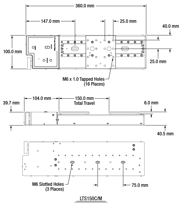
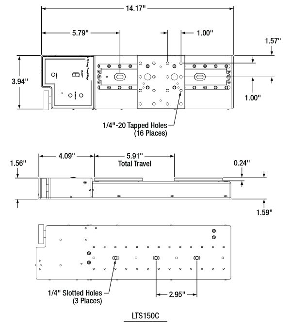
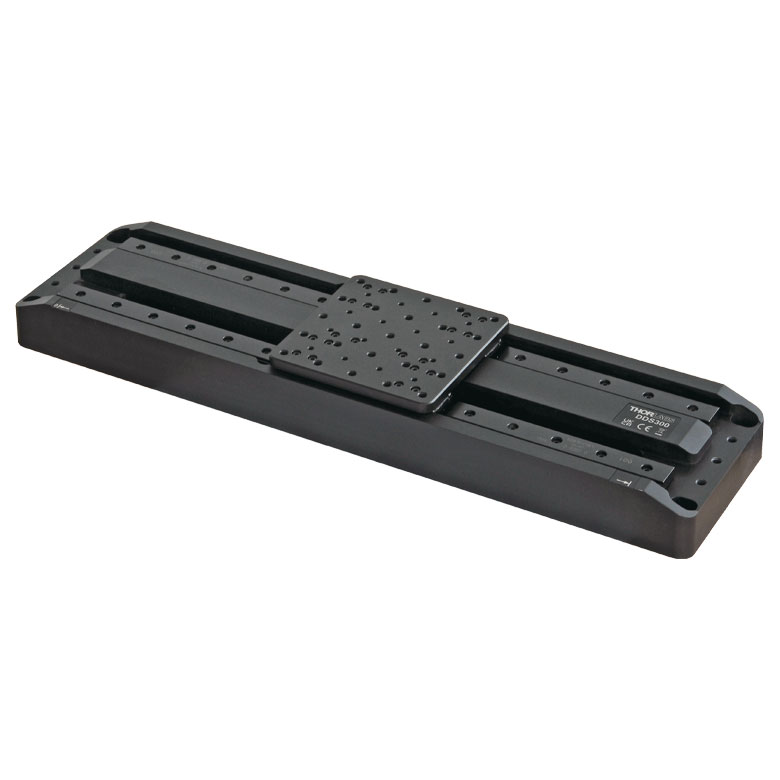
Thorlabs' LTS150C(/M) stage provides 150 mm (5.9") of travel with an integrated stepper motor and controller. The controller features manual keypad and remote computer control. Optomechanics can be directly mounted to the moving platform using sixteen 1/4"-20 (M6) tapped holes, which are spaced 1.0" (25.0 mm) apart.

 Zoom
Zoom
- Mount LTS150C(/M) and LTS300C(/M) Stages in XY Configurations
- Stages can be Mounted in Left- or Right-Handed Setups
- Dowels Included to Ensure Orthogonality
The LTSP1(/M) is a spacer plate, allowing any two LTS translation stages to be mounted in an XY configuration. When assembled as shown to the right, the working height of the upper stage is 3.15" (80 mm). The spatial dimensions of the stage configuration will depend on the orientation (left-handed or right-handed) of the X and Y stages. Please contact Tech Support for the exact dimensions of a particular setup.

 Zoom
Zoom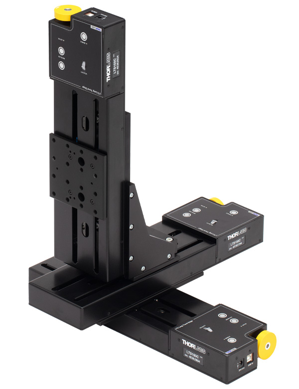
Click to Enlarge
Three LTS150C Stages Mounted
in XYZ Configuration Using an
LTSP1 Plate and LTSP2 Bracket

- Mount an LTS150C(/M) Stage in XZ and XYZ Configurations
- Stage can be Mounted in Left- or Right-Handed Setups
- Not Designed for Direct Breadboard Mounting (See Below)
The LTSP2(/M) right angle bracket allows an LTS150C(/M) stage to be mounted in a vertical (Z-axis) orientation as shown to the right. XYZ configurations can be made using an LTSP1(/M) adapter plate (sold above) and LTSP2(/M) angle bracket.
Please note that these adapters are not designed for mounting directly to a breadboard. The bottom of the vertical stage extends past the base of the adapter, and thus, the adapter must be elevated above the table to provide adequate clearance for the stage.