 Products Home / Imaging Components / Stages for Microscopy / Rigid Stand Translation Stages / Motorized Translation Stages for Rigid Stands
Motorized Translation Stages for Rigid Stands
- Precise Motorized Positioning of Experimental Apparatus
- 1" (25.4 mm) Travel in X and/or Y Axes
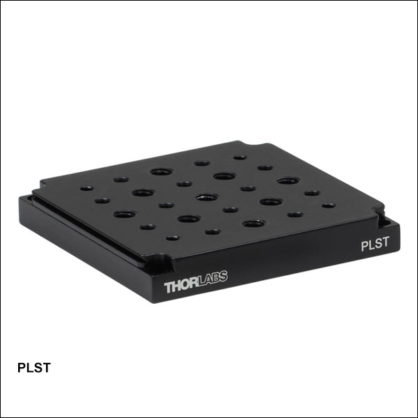
- PLST Top Plate (Sold Separately) Enables Integration with Thorlabs' Optomechanics
- Compact Footprint for Space-Constrained Applications
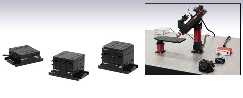
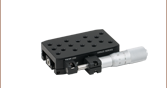
PLSX
One-Axis Translation Stage
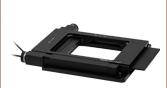
PLSXY
Two-Axis Translation Stage
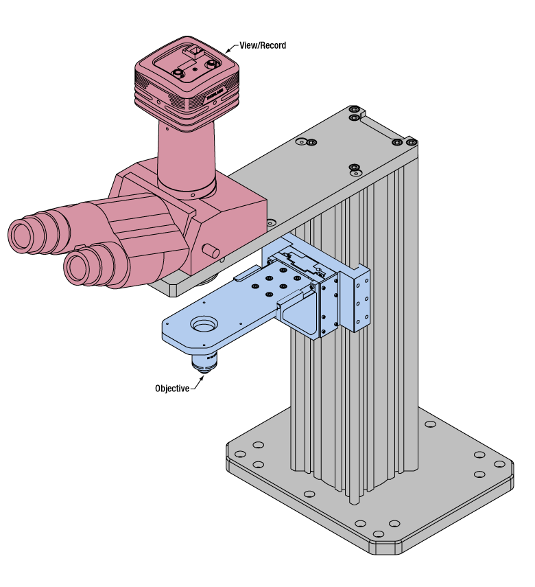
Prelude® Imaging System Using an MP250 Rigid Stand on a PLSXY Stage
The PLSXY stage with PLST top plate offers an array of 1/4"-20 (M6) and 8-32 (M4) mounting holes in addition to a 3" dovetail feature.


Please Wait
Click to Enlarge
PLSXY Stage in Imaging System with Zelux® Camera
Click to Enlarge
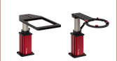
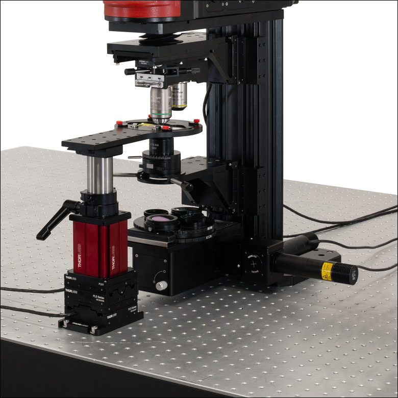
The PLSXY translation stage is used with a manual rigid stand for holding samples under the objective.

Click to Enlarge
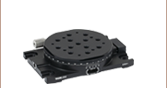
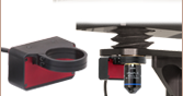
The PLST plate can be used to mount an XRR1 rotation stage to a PLSXY translation stage for XY plus rotation functionality.

Click for Details
This schematic of the PLSX top plate shows the mounting holes. Features are identical for the PLSXY top plate but rotated 90° with respect to the base plate.
Features
- Precise Motion Control in One or Two Dimensions
- Minimum Achievable Incremental Motion of 424 nm
- High Horizontal Load Capacity:
- PLSX Stage: 33.1 lbs (15.0 kg)
- PLSXY Stage: 31.8 lbs (14.4 kg)
- Compact Footprint (3.00" x 4.50") for Space-Constrained Systems
- Use with Motorized Vertical Rigid Stand (Sold Separately) for Precise Three-Axis Control
Thorlabs' Stepper Motor Translation Stages are ideal for use in microscopy, metrology, optical fiber alignment, interferometry, and other applications requiring high-precision positioning. Offering 1" of linear travel along either one or two axes, the integrated motors allow the stages to maintain a compact footprint while translating up to 33 lbs on their 3" x 3" platforms. The recommended controller for the PLSX and PLSXY stages is our MCM301 Three-Axis Controller, sold separately below.
Mounting Rigid Stands for Microscopy
Thorlabs' MPM250(/M) motorized rigid stands can be mounted directly to the PLSX or PLSXY stage to create motorized XZ or XYZ stages as seen in the image to the top right. To mount the MPM250(/M) stand to the translation stage, simply remove the base plate included with the rigid stand by extracting the four 4-40 cap screws and attach the stand to the PLSX or PLSXY stage using the 4-40 holes in the top plate.
Thorlabs’ manual rigid stands can also be mounted to the PLSX or PLSXY stage using the PLST(/M) top plate (sold separately). To mount, first detach the base plate from the rigid stand using a 2.5 mm balldriver to remove the four M3 cap screws, then use the same four M3 cap screws to secure the PLST(/M) top plate to the rigid stand. Next align the rigid stand and top plate to the PLS stage using two Ø3 mm dowel pins and use a 3/32" balldriver to secure four 4-40 cap screws at the corners.
Since both manual and motorized rigid stands can be used to support a variety of imaging apparatus such as slide holders, petri dish holders, recording chamber holders, platforms, and post holders, their use with the PLS translation stages provides an ideal solution for home-built microscopy setups. The image to the right shows a three-axis imaging platform with a manual rigid stand mounted to a PLSXY stage using the PLST top plate.
The PLSX adds 1.58" (40.0 mm) of fixed height to the manual rigid stands using the PLST(/M) top plate, and 1.13" (28.6 mm) of fixed height to motorized rigid stands. Similarly, the PLSXY adds 2.70" (68.5 mm) of fixed height to the manual rigid stands and 2.25" (57.1 mm) of fixed height to motorized rigid stands.
Expanded Versatility for General Mounting Needs
The PLST(/M) top plate expands the versatility of the PLS stages well beyond microscopy, offering many options for custom mounting needs in metrology, optical fiber alignment, interferometry, and other applications requiring precise linear positioning.
Offering an array of 1/4"-20 (M6) and 8-32 (M4) holes on 1" (25.0 mm) centers, the PLST(/M) top plate enables mounting of our optical posts. In addition, the top plate includes a 3" dovetail feature compatible with our XR series 3" dovetail stages and accessories, allowing construction of multi-axis systems without the need for additional hardware. With the XRN-A1 or XRN-A2 adapter, the PLST(/M) plate is also compatible with our XRN series 2" dovetail stages.
| Stage Specifications | |||
|---|---|---|---|
| Item # | PLSX | PLSXY | |
| Axes of Travel | One | Two | |
| Travel Range | 1" (25.4 mm) | ||
| Bidirectional Repeatability | 5 µm | ||
| Backlash | 10 µm | ||
| Minimum Achievable Incremental Movement | 424 nm | ||
| Minimum Repeatable Incremental Movement | 1.06 μm | ||
| Maximum Speeda | 7 mm/s | ||
| Maximum Acceleration | 11 mm/s2 | ||
| Weight | 1.46 lbs (0.66 kg) | 2.47 lbs (1.12 kg) | |
| Dimensions (L x W x H) | 4.5" x 3.00" x 1.48" (114.3 x 76.2 x 37.5 mm) |
4.5" x 3.00" x 2.60" (114.3 x 76.2 x 66.0 mm) |
|
| Load Capacity | |||
| Stage Mounted Horizontally | Recommended | ≤20 lbs (9.1 kg) | ≤18.2 lbs (8.3 kg) |
| Maximum | 33.1 lbs (15.0 kg) | 31.8 lbs (14.4 kg) | |
| Stage Mounted Vertically | Recommended | ≤5 lbs (2.3 kg) | ≤3 lbs (1.4 kg) |
| Maximum | 8.0 lbs (3.6 kg) | 6.0 lbs (2.7 kg) | |
| Stepper Motor Specifications | |
|---|---|
| Cable Length | 6' (1.8 m) |
| Thread Screw Pitch |
0.3 mm |
| Step Angle | 1.8° |
| Limit Switches | Hall Effect Sensors |
| Phase Current | 0.49 A |
| Phase Resistance | 5.1 Ω |
| Insulation Resistance | 20 MΩ |
| Recommended Controller | MCM301 |
Building a Cerna® Microscope
The Cerna microscopy platform's large working volume and system of dovetails make it straightforward to connect and position the components of the microscope. This flexibility enables simple and stable set up of a preconfigured microscope, and provides easy paths for later upgrades and modification. See below for a couple examples of the assembly of some DIY Cerna microscopes.
DIY Cerna Design and Assembly
Walkthrough of a DIY Microscope Configuration
This DIY microscope uses a CSA3000(/M) Breadboard Top, a CSA2001 Dovetail Adapter, our CSA1001 and CSA1002 Fixed Arms, and other body attachments and extensions. These components provide interfaces to our lens tube and cage construction systems, allowing the rig to incorporate two independent trans-illumination modules, a home-built epi-illumination path, and a custom sample viewing optical path.
The simplicity of Thorlabs optomechanical interfaces allows a custom DIY microscope to be quickly assembled and reconfigured for custom imaging applications.
Click on the different parts of the microscope to explore their functions.
Elements of a Microscope
This overview was developed to provide a general understanding of a Cerna® microscope. Click on the different portions of the microscope graphic to the right or use the links below to learn how a Cerna microscope visualizes a sample.
Terminology
Arm: Holds components in the optical path of the microscope.
Bayonet Mount: A form of mechanical attachment with tabs on the male end that fit into L-shaped slots on the female end.
Bellows: A tube with accordion-shaped rubber sides for a flexible, light-tight extension between the microscope body and the objective.
Breadboard: A flat structure with regularly spaced tapped holes for DIY construction.
Dovetail: A form of mechanical attachment for many microscopy components. A linear dovetail allows flexible positioning along one dimension before being locked down, while a circular dovetail secures the component in one position. See the Microscope Dovetails tab or here for details.
Epi-Illumination: Illumination on the same side of the sample as the viewing apparatus. Epi-fluorescence, reflected light, and confocal microscopy are some examples of imaging modalities that utilize epi-illumination.
Filter Cube: A cube that holds filters and other optical elements at the correct orientations for microscopy. For example, filter cubes are essential for fluorescence microscopy and reflected light microscopy.
Köhler Illumination: A method of illumination that utilizes various optical elements to defocus and flatten the intensity of light across the field of view in the sample plane. A condenser and light collimator are necessary for this technique.
Nosepiece: A type of arm used to hold the microscope objective in the optical path of the microscope.
Optical Path: The path light follows through the microscope.
Rail Height: The height of the support rail of the microscope body.
Throat Depth: The distance from the vertical portion of the optical path to the edge of the support rail of the microscope body. The size of the throat depth, along with the working height, determine the working space available for microscopy.
Trans-Illumination: Illumination on the opposite side of the sample as the viewing apparatus. Brightfield, differential interference contrast (DIC), Dodt gradient contrast, and darkfield microscopy are some examples of imaging modalities that utilize trans-illumination.
Working Height: The height of the support rail of the microscope body plus the height of the base. The size of the working height, along with the throat depth, determine the working space available for microscopy.
 Click to Enlarge
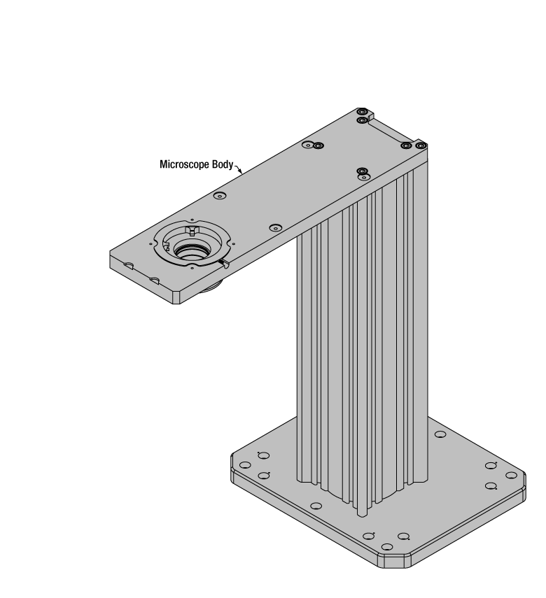
Cerna Microscope Body
Click to Enlarge
Body Details
Microscope Body
The microscope body provides the foundation of any Cerna microscope. The support rail utilizes 95 mm rails machined to a high angular tolerance to ensure an aligned optical path and perpendicularity with the optical table. The support rail height chosen (350 - 600 mm) determines the vertical range available for experiments and microscopy components. The 7.74" throat depth, or distance from the optical path to the support rail, provides a large working space for experiments. Components attach to the body by way of either a linear dovetail on the support rail, or a circular dovetail on the epi-illumination arm (on certain models). Please see the Microscope Dovetails tab or here for further details.
 Click to Enlarge
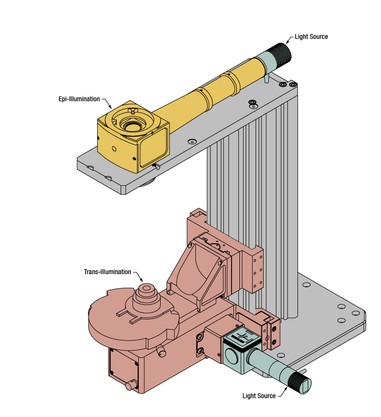
Illumination with a Cerna microscope can come from above (yellow) or below (orange). Illumination sources (green) attach to either.
Illumination
Using the Cerna microscope body, a sample can be illuminated in two directions: from above (epi-illumination, see yellow components to the right) or from below (trans-illumination, see orange components to the right).
Epi-illumination illuminates on the same side of the sample as the viewing apparatus; therefore, the light from the illumination source (green) and the light from the sample plane share a portion of the optical path. It is used in fluorescence, confocal, and reflected light microscopy. Epi-illumination modules, which direct and condition light along the optical path, are attached to the epi-illumination arm of the microscope body via a circular D1N dovetail (see the Microscope Dovetails tab or here for details). Multiple epi-illumination modules are available, as well as breadboard tops, which have regularly spaced tapped holes for custom designs.
Trans-illumination illuminates from the opposite side of the sample as the viewing apparatus. Example imaging modalities include brightfield, differential interference contrast (DIC), Dodt gradient contrast, oblique, and darkfield microscopy. Trans-illumination modules, which condition light (on certain models) and direct it along the optical path, are attached to the support rail of the microscope body via a linear dovetail (see Microscope Dovetails tab or here). Please note that certain imaging modalities will require additional optics to alter the properties of the beam; these optics may be easily incorporated in the optical path via lens tubes and cage systems. In addition, Thorlabs offers condensers, which reshape input collimated light to help create optimal Köhler illumination. These attach to a mounting arm, which holds the condenser at the throat depth, or the distance from the optical path to the support rail. The arm attaches to a focusing module, used for aligning the condenser with respect to the sample and trans-illumination module.
 |
 |
 |
 |
 |
 |
 |
 |
| Epi-Illumination Modules | Breadboards & Body Attachments |
Brightfield | DIC | Dodt | Condensers | Condenser Mounting | Light Sources |
 Click to Enlarge
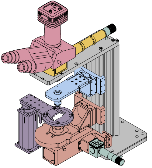
Light from the sample plane is collected through an objective (blue) and viewed using trinocs or other optical ports (pink).
Sample Viewing/Recording
Once illuminated, examining a sample with a microscope requires both focusing on the sample plane (see blue components to the right) and visualizing the resulting image (see pink components).
A microscope objective collects and magnifies light from the sample plane for imaging. On the Cerna microscope, the objective is threaded onto a nosepiece, which holds the objective at the throat depth, or the distance from the optical path to the support rail of the microscope body. This nosepiece is secured to a motorized focusing module, used for focusing the objective as well as for moving it out of the way for sample handling. To ensure a light-tight path from the objective, the microscope body comes with a bellows (not pictured).
Various modules are available for sample viewing and data collection. Trinoculars have three points of vision to view the sample directly as well as with a camera. Double camera ports redirect or split the optical path among two viewing channels. Camera tubes increase or decrease the image magnification. For data collection, Thorlabs offers both cameras and photomultiplier tubes (PMTs), the latter being necessary to detect fluorescence signals for confocal microscopy. Breadboard tops provide functionality for custom-designed data collection setups. Modules are attached to the microscope body via a circular dovetail (see the Microscope Dovetails tab or here for details).


 Click to Enlarge
The rigid stand (purple) pictured is one of various sample mounting options available.
Sample/Experiment Mounting
Various sample and equipment mounting options are available to take advantage of the large working space of this microscope system. Large samples and ancillary equipment can be mounted via mounting platforms, which fit around the microscope body and utilize a breadboard design with regularly spaced tapped through holes. Small samples can be mounted on rigid stands (for example, see the purple component to the right), which have holders for different methods of sample preparation and data collection, such as slides, well plates, and petri dishes. For more traditional sample mounting, slides can also be mounted directly onto the microscope body via a manual XY stage. The rigid stands can translate by way of motorized stages (sold separately), while the mounting platforms contain built-in mechanics for motorized or manual translation. Rigid stands can also be mounted on top of the mounting platforms for independent and synchronized movement of multiple instruments, if you are interested in performing experiments simultaneously during microscopy.
 |
 |
 |
 |
 |
| Translating Platforms | Rigid Stands | Translation Stages for Rigid Stands | Motorized XY Stages | Manual XY Stage |
For sample viewing, Thorlabs offers trinoculars, double camera ports, and camera tubes. Light from the sample plane can be collected via cameras, photomultiplier tubes (PMTs), or custom setups using breadboard tops. Click here for additional information about viewing samples with a Cerna microscope.
| Product Families & Web Presentations | |||
 |
|
 |
 |
| Sample Viewing | Breadboards & Body Attachments |
Cameras | PMTs |
Microscope objectives are held in the optical path of the microscope via a nosepiece. Click here for additional information about viewing a sample with a Cerna microscope.
| Product Families & Web Presentations | ||||
 |
 |
 |
 |
 |
| Objectives | Objective Thread Adapters | Parfocal Length Extender | Piezo Objective Scanner | Objective Mounting |
Large and small experiment mounting options are available to take advantage of the large working space of this microscope. Click here for additional information about mounting a sample for microscopy.
| Product Families & Web Presentations | ||||
|
|
|
|
 |
| Translating Platforms | Rigid Stands | Translation Stages for Rigid Stands | Motorized XY Stages | Manual XY Stage |
Thorlabs offers various light sources for epi- and trans-illumination. Please see the full web presentation of each to determine its functionality within the Cerna microscopy platform.
| Product Families & Web Presentations | ||||
 |
 |
 |
 |
|
| Trans-Illumination Kits | Solis™ High-Power LEDs | Mounted LEDs | X-Cite® Lamps | Other Light Sources |
Epi-illumination illuminates the sample on the same side as the viewing apparatus. Example imaging modalities include fluorescence, confocal, and reflected light microscopy. Click here for additional information on epi-illumination with Cerna.
| Product Families & Web Presentations | ||
|
|
|
| Epi-Illumination | Body Attachments | Light Sources |
Trans-illumination illuminates from the opposite side of the sample as the viewing apparatus. Example imaging modalities include brightfield, differential interference contrast (DIC), Dodt gradient contrast, oblique, and darkfield microscopy. Click here for additional information on trans-illumination with Cerna.
| Product Families & Web Presentations | ||||||
|
|
|
|
 |
|
|
| Brightfield | DIC | Dodt | Condensers | Condenser Mounting | Illumination Kits | Other Light Sources |
The microscope body provides the foundation of any Cerna microscope. The 7.74" throat depth provides a large working space for experiments. Click here for additional information about the Cerna microscope body.
| Product Families & Web Presentations | |
 |
 |
| Microscope Bodies | Microscope Translator |
| Posted Comments: | |
Joel LeBlanc
(posted 2023-08-16 13:27:58.58) Hi! I want to integrate the PLS-X in a design, and I need to know the load rating for vertical mounting. However, the wording in the description is ambiguous: is the vertical max load applicable when the motion axis is the same as the gravity axis (in other words, is the vertical max load the maximal mass the stage can move upwards?)
thanks jpolaris
(posted 2023-08-17 03:35:52.0) Thank you for contacting Thorlabs. Your interpretation of vertical load capacity is correct. Vertical load capacity is the amount of mass the stage can lift against gravity. For PLS-X specifically, the vertical load capacity is 8 lbs (3.6 kg), but we recommend keeping the load under 5 lbs (2.3 kg) when possible. user
(posted 2023-02-10 10:26:13.243) 三个轴只使用了X轴,发运动命令后等待StatusPosition状态时间长,请问如何解决? cdolbashian
(posted 2023-02-17 11:23:41.0) Thank you for reaching out to us with this inquiry. We are sorry to hear the particular issues you are having while communicating with your MCM3000 device. Your local office will reach out to you to help troubleshoot this issue. For future tech support questions, please feel free to contact aforementioned local office at techsupport-cn@thorlabs.com user
(posted 2021-10-12 06:25:21.713) Hello! I am using the ZFM2020 focusing module. The motor has been damaged, probably because of a high load. I would like to replace the translation stage. Would it be possible to buy the PLS-X, remove the base and the top plates and attach the translation stage to the corresponding plates of my ZFM2020? It seems that the translation stage is exactly the same in the PLS-X and in the ZFM2020 and that only the base and the top plates differ. It would substantially reduce the overall cost. Thank you for your response. cdolbashian
(posted 2021-10-28 04:16:01.0) Thank you for reaching out to us at Thorlabs. The stage for both of these parts are identical, as you note, and the top plate/mounting option is the only real difference. Simply replacing the type of mounting will not prevent damage to the driving mechanism via large load. I have reached out to you directly to come up with other options, based on your application. Vasily Goncharov
(posted 2021-04-20 14:24:30.7) The travel range of this stage is actually around 30-32 mm, not 25.4 mm as stated in the specifications. Is there an easy way to restrict the travel range to the specified 25.4 mm range? cdolbashian
(posted 2021-05-06 11:03:31.0) Thank you for contacting us here at ThorLabs! When operating this stage with our software, you can simply set the final location at 1". While we list 1" as the travel distance, a more accurate notation would be "at least" 1". The stages tend to translate closer to 30mm, as you have noticed. When operating with the knobs alone, and not the software, there is no built-in way to restrict the full range of motion. Esmeralda Fonseca
(posted 2020-02-05 16:01:05.933) Hi!
I am interested in getting a motorized stage that allows me to position a black plastic square just in the middle of a mouse face. This black plastic square will have 4 needles coming out of it, two on the left and two on the right. One pair of needles will be more medial (to deliver water as a reward) and two needles will be more lateral to deliver air-puffs to the mouse whiskers. In order to permit the symmetrical delivery of the air puffs, we will need to adjust the position of the needles in XYZ axis (anteroposterior, lateromedial and dorsoventral). It is preferable that this is motorized and not manual. This motorized stage will be placed on a MB3030/M. Which suggestions do you have? If you have any spanish-speaker it would be helpful. Thanks a lot! YLohia
(posted 2020-03-11 05:00:48.0) Hello Esmeralda, thank you for contacting Thorlabs. A Spanish-speaking applications engineer reached out to you directly at the time of your original post. If you have further questions regarding this, please feel free to call us or reply to our direct conversation. |

 Zoom
Zoom
Click to Enlarge
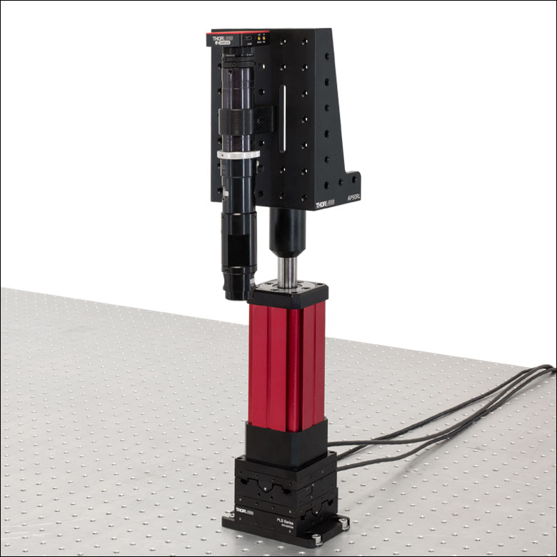
XYZ Stage with a Slide Holder Using the MPM250 Rigid Stand and PLSXY Stage
- Fine Motorized Movement for Precise-Positioning Applications
- Maximum Horizontal Load Capacity: 33.1 lbs (15.0 kg)
- Compact Footprint: 3.00" x 4.50" (76.2 mm x 114.3 mm)
- One or Two Axes of Travel:
- PLSX: One-Axis Translation Stage
- PLSXY: Two-Axis Translation Stage
These versatile 1D or 2D stepper motor translation stages provide 1" of travel for use in a wide variety of applications. The PLSX stage provides linear travel along one axis, while the PLSXY stage provides linear travel along two axes. A 6' (1.8 m) long permanently-attached cable allows the stage to be connected to the MCM301 Controller (available below).
Each stage includes a 3.00" x 4.50" (76.2 mm x 114.3 mm) base plate that contains four 1/4" (M6) counterbored slots for securing the stage to an optical table or workstation.

 Zoom
Zoom| Compatible Stages | |
|---|---|
| Translation Stages for Rigid Stands | |
| Motorized Vertical Rigid Stand | |
| Motorized Focusing Module |
| Controller Specifications |
|---|
| Compatible Motor Specifications |
|---|
Software
Version 1.0 (November 10, 2023)
The software package contains the installation files
for the GUI interface, driver, and SDK. The software is compatible with Windows® 7 (64 bit) and later systems.
- Designed for Rigid Stand Translation Stages, Motorized Rigid Stand, and Motorized Focusing Module
- Provides Control for up to Three Axes
- Separately Available Joystick Allows Hand-Operation
- Each Axis can be Individually Disabled to Prevent Unintended Movements or to Retain a Position
- Remotely Control Translation Using Standalone Software (Requires 64-Bit Windows® 7 or Later)
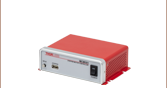
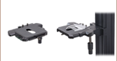
The MCM301 3-Axis Controller is designed for use with Thorlabs' Motorized Rigid Stand Translation Stages, Motorized Vertical Rigid Stand, and Motorized Focusing Module. The MCMK3 3-Knob Joystick, available separately, can be connected to provide hand-operation. The controller can also be operated remotely using standalone software.
When using the optional MCMK3 joystick, each side face of the joystick includes a rotating knob and a push-button switch that are dedicated to a single axis. The push-button switch on the joystick enables and disables the axis and is lit in green when the axis is enabled. Disabling the axis lets the user preserve a position or prevent accidental movements. A dial on the top face adjusts the velocity per rotation of the knobs. For more information on the MCMK3 joystick and how to utilize the USB HID protocol, please see the full web presentation.
Since each MCM301 controller has three channels, a single controller can be used to drive both the MPM250 Vertical Rigid Stand and a PLSXY 2-Axis Linear Translation Stage.
For more information, as well as compatible software and a LabVIEW™/C++/Python SDK, please see the full web presentation for the MCM301 controller.

 Zoom
Zoom
Click for Details
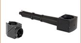
Sample mounting platform attaches to PLSXY stage using a Ø1.5" post on a PLST plate.

- Mounts Manual Rigid Stands, Posts, and 3" Dovetail Rails to PLSX and PLSXY Stages
- Mounting Surface has Nine 1/4"-20 (M6) and Twelve 8-32 (M4) Holes on 1.0" (25.0 mm) Centers
- Directly Compatible with XR Series 3" Dovetail Stages
The PLST/M mounting plate was designed to expand the versatility of the PLSX and PLSXY translation stages sold above. In addition to compatibility with Thorlabs' manual rigid stands, the mounting surface shown in the schematic to the right is compatible with our optical posts, allowing for a large motorized sample area under a microscope for imaging applications as shown in the image to the right. In addition, the top plate includes a 3" dovetail feature compatible with our XR series 3" dovetail stages and accessories, allowing construction of multi-axis systems without the need for additional hardware. With the XRN-A1 or XRN-A2 adapter, the PLST(/M) plate is also compatible with our XRN series 2" dovetail stages.