 Products Home / Optical Tables, Breadboards, and Supports / Solid Aluminum Optical Breadboards / Translating Mounting Platforms
Translating Mounting Platforms
- Translating Breadboard with 1/4"-20 (M6) Mounting Taps
- 2" (50 mm) Manual or Motorized Travel in X and Y
- Translate Entire Workspace Around a Microscope's Optical Path
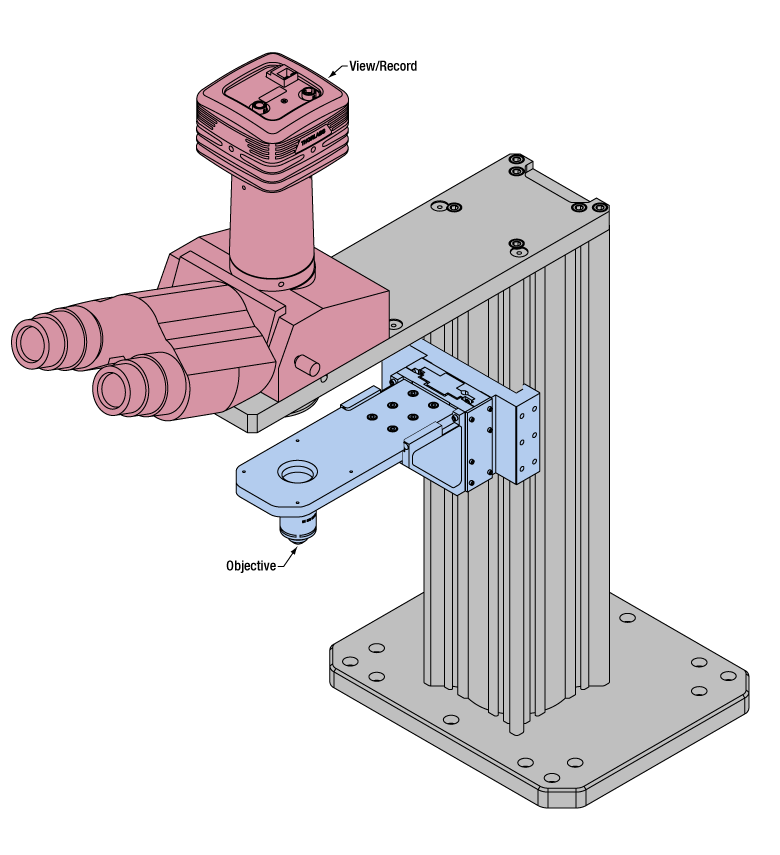
Application Idea
Micromanipulators and Sample Holders Mounted on a Motorized 2D Platform
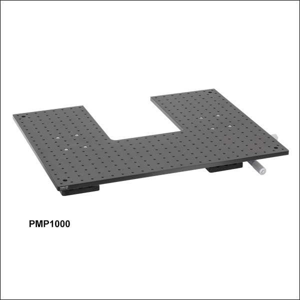
PMP1000
Manual Platform with
1/4"-20 Tapped Holes


Please Wait

Click for Details
Drawing of the Metric Breadboard Platforms
Click for Details
Drawing of the Imperial Breadboard Platforms
Features
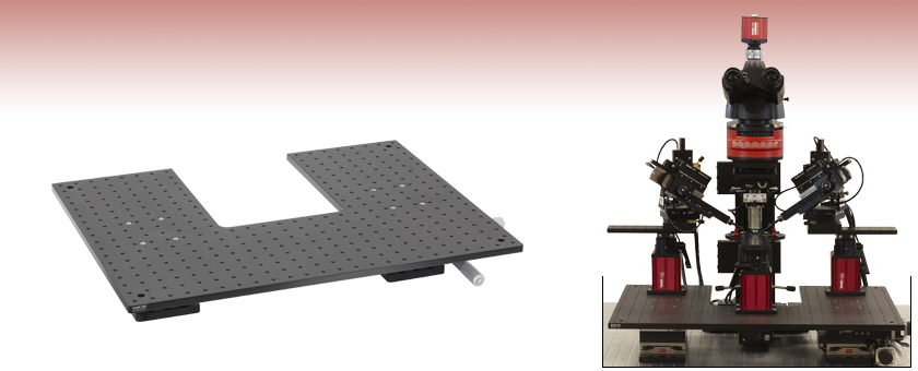
- 24.00" x 18.00" (600 mm x 450 mm) Translating Breadboard
- 8.00" x 10.00" (200 mm x 250 mm) Cutout for Placement Around a Microscope's Optical Path
- 352 1/4"-20 (M6) Taps for Mounting Multi-Component Setups
- 2" (50 mm) Travel via Manual Micrometer or Motorized Stepper Motor Actuator
- Contact Tech Support for Custom Breadboard Options
Thorlabs' Manual and Motorized Translating Breadboards are designed to fit around a microscope's optical path while supporting sample holders, micromanipulators, or multi-component experimental setups. The large 24.00" x 18.00" (600 mm x 450 mm) breadboard allows for multiple components to be mounted and translated at one time while staying fixed in space relative to each another. Each movable baseplate has a 8.00" x 10.00" (200 mm x 250 mm) cutout on one side that provides ample space for modules mounted to the microscope body, such as condenser holders, brightfield illumination modules, and body attachments.
The breadboard is mounted on two XY stage assemblies with micrometers for manual adjustments or stepper motor actuators for motorized adjustments. Each manual or motorized stage assembly can translate the mounted breadboard up to 2" (50 mm) in X and Y. Each breadboard contains an array of 352 1/4"-20 (M6 x 1.0) tapped holes on 1" (25 mm) centers that can be used to secure rigid stands and other experimental equipment, allowing several separate pieces of a large setup to be translated in unison.
Thorlabs can design breadboards for specific needs. Our capabilities include custom sizes up to 24" x 18" (600 mm x 450 mm), custom cutout, and the use of other materials, such as steel. Please contact Tech Support for more information.
Thorlabs also manufactures a Microscope Translator for DIY Cerna® systems, which provides 2" of microscope body travel in X and Y.
Building a Cerna® Microscope
The Cerna microscopy platform's large working volume and system of dovetails make it straightforward to connect and position the components of the microscope. This flexibility enables simple and stable set up of a preconfigured microscope, and provides easy paths for later upgrades and modification. See below for a couple examples of the assembly of some DIY Cerna microscopes.
DIY Cerna Design and Assembly
Walkthrough of a DIY Microscope Configuration
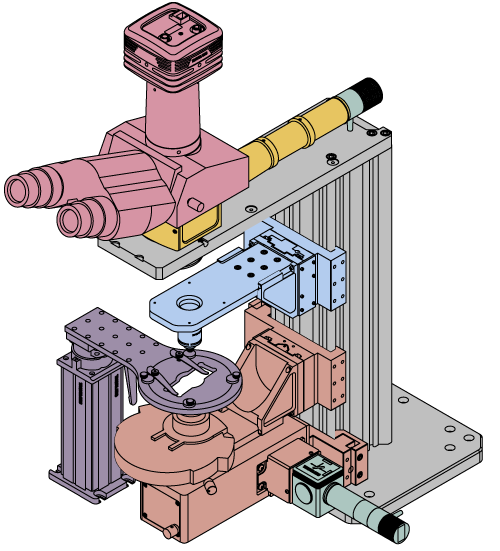
This DIY microscope uses a CSA3000(/M) Breadboard Top, a CSA2001 Dovetail Adapter, our CSA1001 and CSA1002 Fixed Arms, and other body attachments and extensions. These components provide interfaces to our lens tube and cage construction systems, allowing the rig to incorporate two independent trans-illumination modules, a home-built epi-illumination path, and a custom sample viewing optical path.
The simplicity of Thorlabs optomechanical interfaces allows a custom DIY microscope to be quickly assembled and reconfigured for custom imaging applications.
| Posted Comments: | |
Hui Zhang
(posted 2023-03-24 23:55:54.887) could you please send me a quote?
This is the best manual one.
I have 30 years EP experience. ksosnowski
(posted 2023-03-28 12:57:05.0) Thanks for reaching out to Thorlabs. For inquiries like this we recommend reaching out directly to techsupport@thorlabs.com. I have reached out directly to discuss this request further. jiaruili
(posted 2016-11-22 17:21:51.82) We are looking for the translation stage for our cryostat (~35 pound) with sub micron accuracy. The Motorized Translating Breadboard looks good for us. So what is the height of the motorized stage? And can you make it's size smaller (~30*20cm)?
Thanks, tfrisch
(posted 2016-11-30 09:35:58.0) Hello, thank you for contacting Thorlabs. I see that you are already in contact with Ben about our custom capabilities. The height of the motorized breadboard is 116.7mm. user
(posted 2015-08-19 10:42:17.6) For the PLS stage, we would like to control with Labview. Is a driver included?
We really need one axis controller. besembeson
(posted 2015-09-29 11:27:07.0) Response from Bweh at Thorlabs USA: We have a Labview SDK for the MCM3000. Please contact me at techsupport@thorlabs.com and I will provide this to you. |
Click on the different parts of the microscope to explore their functions.
Elements of a Microscope
This overview was developed to provide a general understanding of a Cerna® microscope. Click on the different portions of the microscope graphic to the right or use the links below to learn how a Cerna microscope visualizes a sample.
Terminology
Arm: Holds components in the optical path of the microscope.
Bayonet Mount: A form of mechanical attachment with tabs on the male end that fit into L-shaped slots on the female end.
Bellows: A tube with accordion-shaped rubber sides for a flexible, light-tight extension between the microscope body and the objective.
Breadboard: A flat structure with regularly spaced tapped holes for DIY construction.
Dovetail: A form of mechanical attachment for many microscopy components. A linear dovetail allows flexible positioning along one dimension before being locked down, while a circular dovetail secures the component in one position. See the Microscope Dovetails tab or here for details.
Epi-Illumination: Illumination on the same side of the sample as the viewing apparatus. Epi-fluorescence, reflected light, and confocal microscopy are some examples of imaging modalities that utilize epi-illumination.
Filter Cube: A cube that holds filters and other optical elements at the correct orientations for microscopy. For example, filter cubes are essential for fluorescence microscopy and reflected light microscopy.
Köhler Illumination: A method of illumination that utilizes various optical elements to defocus and flatten the intensity of light across the field of view in the sample plane. A condenser and light collimator are necessary for this technique.
Nosepiece: A type of arm used to hold the microscope objective in the optical path of the microscope.
Optical Path: The path light follows through the microscope.
Rail Height: The height of the support rail of the microscope body.
Throat Depth: The distance from the vertical portion of the optical path to the edge of the support rail of the microscope body. The size of the throat depth, along with the working height, determine the working space available for microscopy.
Trans-Illumination: Illumination on the opposite side of the sample as the viewing apparatus. Brightfield, differential interference contrast (DIC), Dodt gradient contrast, and darkfield microscopy are some examples of imaging modalities that utilize trans-illumination.
Working Height: The height of the support rail of the microscope body plus the height of the base. The size of the working height, along with the throat depth, determine the working space available for microscopy.
 Click to Enlarge
Cerna Microscope Body
Click to Enlarge
Body Details
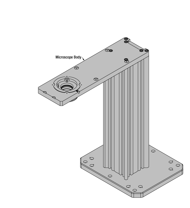
Microscope Body
The microscope body provides the foundation of any Cerna microscope. The support rail utilizes 95 mm rails machined to a high angular tolerance to ensure an aligned optical path and perpendicularity with the optical table. The support rail height chosen (350 - 600 mm) determines the vertical range available for experiments and microscopy components. The 7.74" throat depth, or distance from the optical path to the support rail, provides a large working space for experiments. Components attach to the body by way of either a linear dovetail on the support rail, or a circular dovetail on the epi-illumination arm (on certain models). Please see the Microscope Dovetails tab or here for further details.
 Click to Enlarge
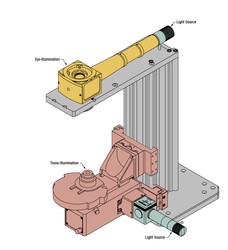
Illumination with a Cerna microscope can come from above (yellow) or below (orange). Illumination sources (green) attach to either.
Illumination
Using the Cerna microscope body, a sample can be illuminated in two directions: from above (epi-illumination, see yellow components to the right) or from below (trans-illumination, see orange components to the right).
Epi-illumination illuminates on the same side of the sample as the viewing apparatus; therefore, the light from the illumination source (green) and the light from the sample plane share a portion of the optical path. It is used in fluorescence, confocal, and reflected light microscopy. Epi-illumination modules, which direct and condition light along the optical path, are attached to the epi-illumination arm of the microscope body via a circular D1N dovetail (see the Microscope Dovetails tab or here for details). Multiple epi-illumination modules are available, as well as breadboard tops, which have regularly spaced tapped holes for custom designs.
Trans-illumination illuminates from the opposite side of the sample as the viewing apparatus. Example imaging modalities include brightfield, differential interference contrast (DIC), Dodt gradient contrast, oblique, and darkfield microscopy. Trans-illumination modules, which condition light (on certain models) and direct it along the optical path, are attached to the support rail of the microscope body via a linear dovetail (see Microscope Dovetails tab or here). Please note that certain imaging modalities will require additional optics to alter the properties of the beam; these optics may be easily incorporated in the optical path via lens tubes and cage systems. In addition, Thorlabs offers condensers, which reshape input collimated light to help create optimal Köhler illumination. These attach to a mounting arm, which holds the condenser at the throat depth, or the distance from the optical path to the support rail. The arm attaches to a focusing module, used for aligning the condenser with respect to the sample and trans-illumination module.
 |
 |
 |
 |
 |
 |
 |
 |
| Epi-Illumination Modules | Breadboards & Body Attachments |
Brightfield | DIC | Dodt | Condensers | Condenser Mounting | Light Sources |
 Click to Enlarge
Light from the sample plane is collected through an objective (blue) and viewed using trinocs or other optical ports (pink).
Sample Viewing/Recording
Once illuminated, examining a sample with a microscope requires both focusing on the sample plane (see blue components to the right) and visualizing the resulting image (see pink components).
A microscope objective collects and magnifies light from the sample plane for imaging. On the Cerna microscope, the objective is threaded onto a nosepiece, which holds the objective at the throat depth, or the distance from the optical path to the support rail of the microscope body. This nosepiece is secured to a motorized focusing module, used for focusing the objective as well as for moving it out of the way for sample handling. To ensure a light-tight path from the objective, the microscope body comes with a bellows (not pictured).
Various modules are available for sample viewing and data collection. Trinoculars have three points of vision to view the sample directly as well as with a camera. Double camera ports redirect or split the optical path among two viewing channels. Camera tubes increase or decrease the image magnification. For data collection, Thorlabs offers both cameras and photomultiplier tubes (PMTs), the latter being necessary to detect fluorescence signals for confocal microscopy. Breadboard tops provide functionality for custom-designed data collection setups. Modules are attached to the microscope body via a circular dovetail (see the Microscope Dovetails tab or here for details).


 Click to Enlarge
The rigid stand (purple) pictured is one of various sample mounting options available.
Sample/Experiment Mounting
Various sample and equipment mounting options are available to take advantage of the large working space of this microscope system. Large samples and ancillary equipment can be mounted via mounting platforms, which fit around the microscope body and utilize a breadboard design with regularly spaced tapped through holes. Small samples can be mounted on rigid stands (for example, see the purple component to the right), which have holders for different methods of sample preparation and data collection, such as slides, well plates, and petri dishes. For more traditional sample mounting, slides can also be mounted directly onto the microscope body via a manual XY stage. The rigid stands can translate by way of motorized stages (sold separately), while the mounting platforms contain built-in mechanics for motorized or manual translation. Rigid stands can also be mounted on top of the mounting platforms for independent and synchronized movement of multiple instruments, if you are interested in performing experiments simultaneously during microscopy.
 |
 |
 |
 |
 |
| Translating Platforms | Rigid Stands | Translation Stages for Rigid Stands | Motorized XY Stages | Manual XY Stage |
For sample viewing, Thorlabs offers trinoculars, double camera ports, and camera tubes. Light from the sample plane can be collected via cameras, photomultiplier tubes (PMTs), or custom setups using breadboard tops. Click here for additional information about viewing samples with a Cerna microscope.
| Product Families & Web Presentations | |||
 |
|
 |
 |
| Sample Viewing | Breadboards & Body Attachments |
Cameras | PMTs |
Microscope objectives are held in the optical path of the microscope via a nosepiece. Click here for additional information about viewing a sample with a Cerna microscope.
| Product Families & Web Presentations | ||||
 |
 |
 |
 |
 |
| Objectives | Objective Thread Adapters | Parfocal Length Extender | Piezo Objective Scanner | Objective Mounting |
Large and small experiment mounting options are available to take advantage of the large working space of this microscope. Click here for additional information about mounting a sample for microscopy.
| Product Families & Web Presentations | ||||
|
|
|
|
 |
| Translating Platforms | Rigid Stands | Translation Stages for Rigid Stands | Motorized XY Stages | Manual XY Stage |
Thorlabs offers various light sources for epi- and trans-illumination. Please see the full web presentation of each to determine its functionality within the Cerna microscopy platform.
| Product Families & Web Presentations | ||||
 |
 |
 |
 |
|
| Trans-Illumination Kits | Solis™ High-Power LEDs | Mounted LEDs | X-Cite® Lamps | Other Light Sources |
Epi-illumination illuminates the sample on the same side as the viewing apparatus. Example imaging modalities include fluorescence, confocal, and reflected light microscopy. Click here for additional information on epi-illumination with Cerna.
| Product Families & Web Presentations | ||
|
|
|
| Epi-Illumination | Body Attachments | Light Sources |
Trans-illumination illuminates from the opposite side of the sample as the viewing apparatus. Example imaging modalities include brightfield, differential interference contrast (DIC), Dodt gradient contrast, oblique, and darkfield microscopy. Click here for additional information on trans-illumination with Cerna.
| Product Families & Web Presentations | ||||||
|
|
|
|
 |
|
|
| Brightfield | DIC | Dodt | Condensers | Condenser Mounting | Illumination Kits | Other Light Sources |
The microscope body provides the foundation of any Cerna microscope. The 7.74" throat depth provides a large working space for experiments. Click here for additional information about the Cerna microscope body.
| Product Families & Web Presentations | |
 |
 |
| Microscope Bodies | Microscope Translator |

 Zoom
Zoom| Specifications | |
|---|---|
| Micrometer Travel Range | 50 mm |
| Micrometer Graduations | 10 µm per Division |
| Travel per Revolution | 0.5 mm |
| Runout Over Full Range |
±0.0004" (±10 µm) |
| Maximum Load Capacity Mounted Horizontallya |
20.7 kg (45.71 lbs) |
- 50 mm Manual Travel in Both X and Y
- 24" x 18" (600 mm x 450 mm) Platform
- 352 1/4"-20 (M6 x 1.0) Tapped Holes for Securing Equipment
- 4.59" (116.7 mm) Breadboard Surface Height
- Supports Setups that Access the Optical Path from the Front and the Sides
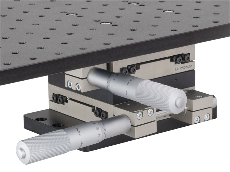
Thorlabs' PMP1000(/M) Manual Platform is designed to support multi-component experimental setups that need to be placed around the vertical optical path of a microscope system. The platform is mounted on two XY stage assemblies with manual micrometers that provide up to 50 mm of travel.
The aluminum breadboard contains an array of 352 1/4"-20 (M6 x 1.0) tapped holes on 1" (25 mm) centers that can be used to secure rigid stands and other experimental equipment. This allows for several separate pieces of a large setup to be translated in unison.
As shown by the drawings above, the surface area of the breadboard measures 24" x 18" (600 mm x 450 mm). The majority of the footprint is contained within this surface area, except for the adjusters that protrude slightly past the right and front edges. When installed on a workstation, the top of the breadboard will sit 4.58" (116.4 mm) above the workstation's surface. It is supported by two base plates underneath the breadboard, which contain counterbores that are spaced to mate with typical 1/4"-20 and M6 x 1.0 tapped hole patterns.
Thorlabs can design the breadboard to your specific needs. This includes custom sizes up to 24" x 18" (600 mm x 450 mm), cutouts, or materials, such as steel. Please contact Tech Support for more information. Please see the PMP-2XY below for a motorized platform.

 Zoom
Zoom| Specifications | |
|---|---|
| Travel Range | 2" (50.8 mm) |
| Velocity (Max) | 3.66 mm/s |
| Encoder Resolution | 0.5 µm |
| Steps per Revolution of Leadscrew | 200 |
| Step Angle | 1.8° |
| Manual Travel per Revolution of Leadscrewa |
1 mm/rev |
| Maximum Load Capacity Mounted Horizontallyb |
34.0 kg (74.96 lbs) |
| Cable Length | 500 mm (1.64 ft) |
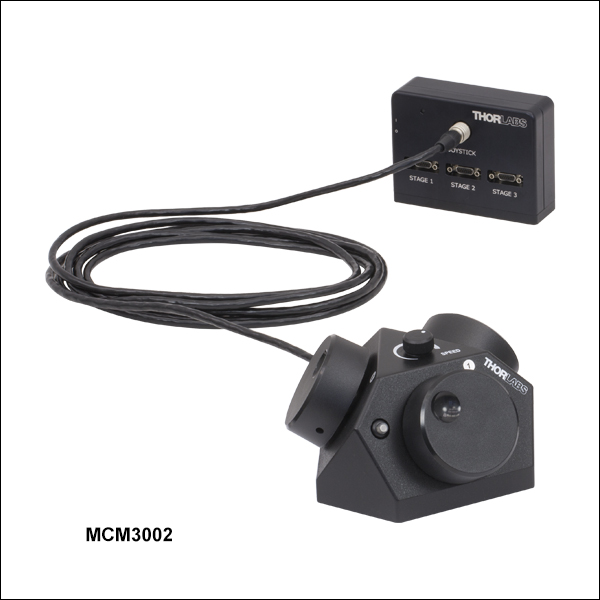
| Required Controller | MCM3002 |
Click for Details
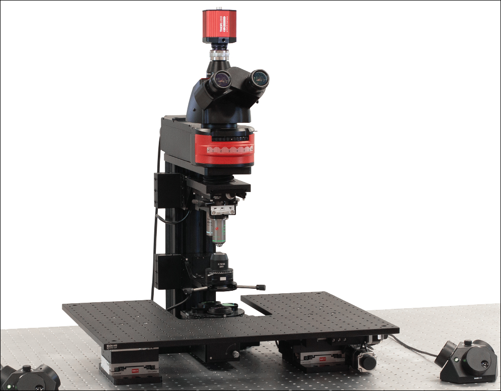
Empty Translating Platform Around a Home-Built DIY Cerna® Microscope
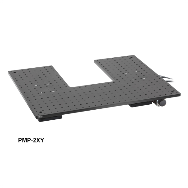
- 2" Motorized Travel in Both X and Y
- 24" x 18" (600 mm x 450 mm) Platform
- 352 1/4"-20 (M6 x 1.0) Tapped Holes for Securing Equipment
- 4.59" (116.7 mm) Breadboard Surface Height
- Supports Setups that Access the Optical Path from the Front and the Sides
- Requires Our Standard 3-Axis Controller (Item # MCM3002, Sold Separately Below)
Thorlabs' PMP-2XY(/M) Motorized Platform is designed to support multi-component experimental setups that need to be placed around the vertical optical path of a microscope system. The motorized design minimizes the amount of interaction needed with the system compared to the manual version above. One MCM3002 controller, sold separately below, is required for operation.
The platform is mounted on two XY stage assemblies that utilize stepper motor actuators to provide up to 2" of motorized travel. When powered off, the motors can be manually adjusted using a rear-located knob.
The aluminum breadboard contains an array of 352 1/4"-20 (M6 x 1.0) tapped holes on 1" (25 mm) centers that can be used to secure rigid stands and other experimental equipment. This allows for several separate pieces of a large setup to be translated in unison.
As shown by the drawings above, the surface area of the breadboard measures 24" x 18" (600 mm x 450 mm). The majority of the footprint is contained within this surface area, except for an actuator that protrudes slightly past the right edge. When installed on the workstation, the top of the breadboard will sit 4.58" (116.4 mm) above the workstation's surface. It is supported by two base plates underneath the breadboard, which contain counterbores that are spaced to mate with typical 1/4"-20 and M6 x 1.0 tapped hole patterns.
Thorlabs can design the breadboard to your specific needs. This includes custom sizes up to 24" x 18" (600 mm x 450 mm), cutouts, or materials, such as steel. Please contact Tech Support for more information.

 Zoom
Zoom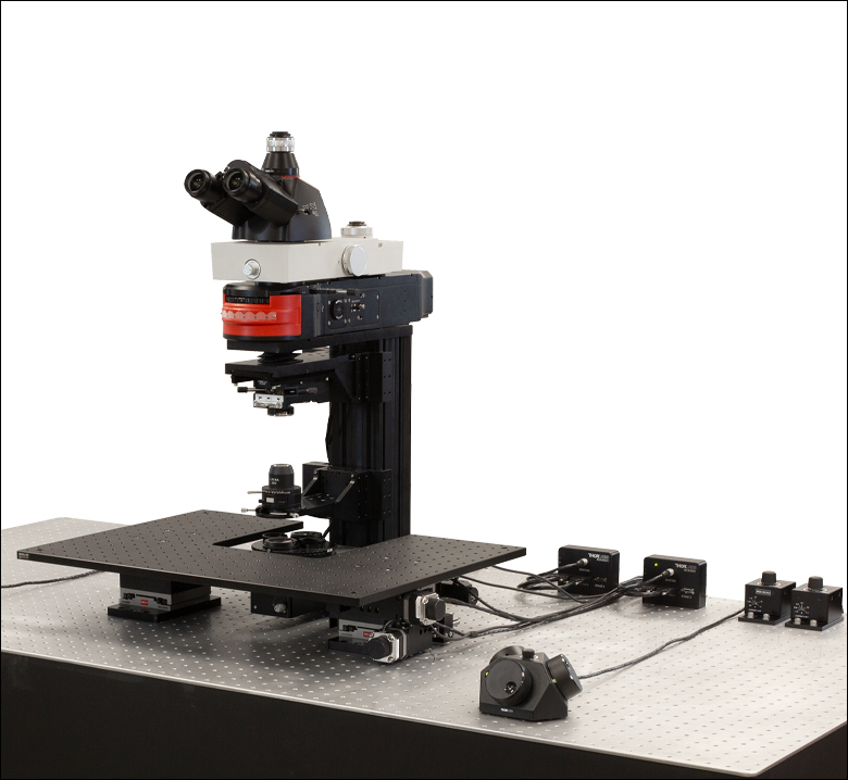
| Compatible Stages |
|---|
| Microscope Body Translator |
| Translating Platforms |
| Controller Specifications |
|---|
| Compatible Motor Specifications |
|---|
- Designed for Cerna Components with 2" Motorized Travel
- Knobs Provide Hand-Operated Control for up to Three Axes
- Each Axis can be Individually Disabled to Prevent Unintended Movements or to Retain a Position
- Adjust Translation Speed via Top-Located Knob
The MCM3002 3-Axis Controller consists of a hand-operated knob box and a separate controller. Each side face of the knob box includes a rotating knob and a push-button switch that are dedicated to a single axis. The push-button switch enables and disables the axis, and is lit in green when the axis is enabled. Disabling the axis lets the user preserve a position or prevent accidental movements. A smaller knob on the top face adjusts the amount of translation per rotation of the knob (see the Controller Specifications table for details).
Since each MCM3002 controller has three channels, you only need to purchase enough channels for each of the modules you intend to drive. For example, a Cerna microscope equipped with a PMP-2XY Translating Platform (which has two axes) only requires one MCM3002 controller.
The MCM3002 is compatible with motorized Cerna components that have a travel range of 2", such as our Microscope Body Translator and Translating Platforms; see the Compatible Motor Specifications table above for use with alternate motorized products. For components with a 1" travel range, such as our Translation Stages and Motorized Focusing Modules, the MCM3001 controller should be used instead. If you would like a controller configured to drive more than one type of stage, please contact Tech Support.
The MCM3002 includes cables for compatibility with all Thorlabs stages. The software may be used with nay stage.
SDK and LabVIEW examples are available by contacting Tech Support.