 Products Home
Illumination Kits

- Designed for Use with DIY Cerna® Trans-Illumination Modules
- Useful for Brightfield, Oblique, Dodt Contrast, DIC Imaging, and Other Modalities
- Includes Warm White and/or IR LED with Collimated Output
WFA1051
Warm White & IR Illumination Kit
(LED Driver Sold Separately)
WFA1010
Warm White Illumination Kit
(LED Driver Sold Separately)
Illumination Kits are Used to Image Thin Samples


Please Wait

Click to Enlarge
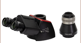
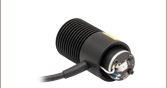
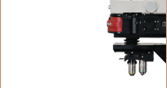
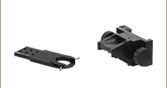
The mounted LED is connected to an SM1 lens tube assembly that holds pre-aligned, AR-coated collimating lenses. The lens tube assembly is then connected to an SM1T2 Lens Tube Coupler and a DFM1 Filter Cube. Four Cage Rods (included with the trans-illumination module) are threaded into the 30-mm-cage-compatible filter cube. Finally, the filter cube is inserted into the trans-illumination module.
Features
- Includes Warm White and/or IR LED, Mounting Hardware, and Collimating/Beam Combining Optics
- Incorporates Filter Cube with SM1 Threads and 30 mm Cage Compatibility for Future Expansion
- Connects Directly to DIY Cerna® Trans-Illumination Modules
- Quickly Interchange Filter Sets with Repeatable Alignment Using DFM1T1 Filter Cube Tops (Sold Separately)
- Compatible with Thorlabs' LED Drivers
Designed for DIY Cerna systems, these Illumination Kits generate intense visible and/or NIR illumination for transmitted light imaging modalities. For Thorlabs' Cerna microscopy system this includes brightfield microscopy, Dodt contrast, and DIC imaging modules. They consist of one or two of Thorlabs' mounted LEDs and a pre-configured optomechanical assembly that adapts the LED to the input optical port on our WFA1000 and WFA1100 Trans-Illumination Modules. The LEDs used by our stock illumination kits offer a long lifetime of >50 000 hours. For control of the output intensity, we offer a variety of drivers that are available below; all of these drivers support modulation via an external source.
We offer three versions of these kits: one with a visible, warm white LED (Item # WFA1010), one with an NIR LED (Item # WFA1020), and one with both (Item # WFA1051). Each LED uses one of the three available ports of a DFM1/M filter cube. Because the WFA1051 illumination kit uses two LEDs, it includes a DMSP805R dichroic mirror that combines the output of both LEDs into a single optical path. This dichroic mirror has industry-standard dimensions of 25 mm x 36 mm x 1 mm and is installed into the DFM1/M filter cube. To increase functionality further, multiple DFM1/M cubes can be connected using 30 mm cage rods. For custom assemblies using different LEDs, the included dichoic mirror can be replaced using any 25 mm x 36 mm dichroic mirror or silver mirror with a thickness of ≤2 mm.
The pre-configured optomechanical assembly is shown in detail in the image to the right. This assembly connects the mounted LED to the trans-illumination module using a selection of Thorlabs' SM1 and 30 mm cage components. Our mounted LEDs emit diverging illumination, so the lens tubes next to the mounted LED contain pre-aligned, AR-coated collimating lenses, which prepare the beam for the trans-illumination module and condenser. These lens tubes are mounted to the trans-illumination module via the DFM1/M Filter Cube and four 30 mm cage rods (included with the trans-illumination module). Each side of the filter cube has an internally SM1-threaded (1.035"-40) port and four 4-40 taps for our 30 mm cage systems. There is no diffuser built-in to these illumination kits. Therefore, if they are used in conjunction with a home-built trans-illumination module we recommend using a diffuser to further improve the output profile of the beam for use in the condenser.
Because the DFM1/M filter cube accepts industry-standard dichroic mirrors and has SM1 and 30 mm cage compatibility, home-built illumination schemes are also possible using Thorlabs' other components. In particular, it is simple to replace the included mounted LED and dichroic mirror with another mounted LED or dichroic mirror later, making it easy to configure the DIY Cerna system with targeted narrowband illumination. Additionally, DFM1T1 inserts, available below, allow for different filters to be swapped in and out of our illumination kits without disassembling the system. Please contact Tech Support for custom-configured LED options.
| Illumination Kit Item # |
Collimating Lenses |
Output Beam Diameter |
Dichroic Mirror |
LED Specificationsa | |||||||||
|---|---|---|---|---|---|---|---|---|---|---|---|---|---|
| Item # | Color (Click for Spectrum)b |
Nominal Wavelengthb |
Power Output (Min/Typ)b |
Maximum Current (CW) |
Forward Voltage |
Bandwidth (FWHM) |
Electrical Power |
Viewing Angle |
Typical Lifetimec |
||||
| WFA1010 | ACL12708U-A |
Ø1" (25.4 mm) |
- | MWWHL4 | Warm White | 3000 Kd | 570 mW / 640 mW |
1000 mA | 2.85 V | N/A | 3.000 W | 120° | >50 000 h |
| WFA1020 | ACL12708U-B |
Ø1" (25.4 mm) |
- | M850L3 | IR | 850 nm | 900 mW / 1100 mW |
1000 mA | 2.9 V | 30 nm | 2.900 W | 90° | 100 000 h |
| WFA1051 | ACL12708U-A |
Ø1" (25.4 mm) |
DMSP805R | MWWHL4 | Warm White | 3000 Kd | 570 mW / 640 mW |
1000 mA | 2.85 V | N/A | 3.000 W | 120° | >50 000 h |
ACL12708U-B |
Ø1" (25.4 mm) |
M850L3 | IR | 850 nm | 900 mW / 1100 mW |
1000 mA | 2.9 V | 30 nm | 2.900 W | 90° | 100 000 h | ||
Building a Cerna® Microscope
The Cerna microscopy platform's large working volume and system of dovetails make it straightforward to connect and position the components of the microscope. This flexibility enables simple and stable set up of a preconfigured microscope, and provides easy paths for later upgrades and modification. See below for a couple examples of the assembly of some DIY Cerna microscopes.
DIY Cerna Design and Assembly
Walkthrough of a DIY Microscope Configuration
This DIY microscope uses a CSA3000(/M) Breadboard Top, a CSA2001 Dovetail Adapter, our CSA1001 and CSA1002 Fixed Arms, and other body attachments and extensions. These components provide interfaces to our lens tube and cage construction systems, allowing the rig to incorporate two independent trans-illumination modules, a home-built epi-illumination path, and a custom sample viewing optical path.
The simplicity of Thorlabs optomechanical interfaces allows a custom DIY microscope to be quickly assembled and reconfigured for custom imaging applications.
| Posted Comments: | |
user
(posted 2019-11-25 03:06:21.78) I wonder if it would be possible to combine a warm white LED and M1650L4 (or M1450L3) in a WFA1051 kit, using some suitable collimator and a dichroic mirror. What are the necessary components? llamb
(posted 2019-11-26 10:45:01.0) Thank you for contacting Thorlabs. If you already have a WFA1051 kit, you can swap out the M850L3 infrared LED from the WFA1051 kit and replace it with either of your two LEDs simply by threading them in/out of the SM1 lens tube. Then, if you choose the M1450L3 LED at 1450 nm, you can swap out the existing DMSP805R dichroic for a dichroic that has 1450 nm in its reflection band, such as our DMSP950R. I have reached out to you directly to discuss your setup details further. wenzel.jakob
(posted 2018-03-19 21:58:33.91) I'm observing some polarization of visible light portion in the illumination kit WFA1015, possibly due to the dichroic mirror? Is this to be expected? YLohia
(posted 2018-03-30 03:26:56.0) Response from Yashasvi at Thorlabs USA: Hello, thank you for contacting Thorlabs. You are correct, this is due to the slight polarizing effects of the dichroic mirror present in the WFA1051. |
Click on the different parts of the microscope to explore their functions.
Elements of a Microscope
This overview was developed to provide a general understanding of a Cerna® microscope. Click on the different portions of the microscope graphic to the right or use the links below to learn how a Cerna microscope visualizes a sample.
Terminology
Arm: Holds components in the optical path of the microscope.
Bayonet Mount: A form of mechanical attachment with tabs on the male end that fit into L-shaped slots on the female end.
Bellows: A tube with accordion-shaped rubber sides for a flexible, light-tight extension between the microscope body and the objective.
Breadboard: A flat structure with regularly spaced tapped holes for DIY construction.
Dovetail: A form of mechanical attachment for many microscopy components. A linear dovetail allows flexible positioning along one dimension before being locked down, while a circular dovetail secures the component in one position. See the Microscope Dovetails tab or here for details.
Epi-Illumination: Illumination on the same side of the sample as the viewing apparatus. Epi-fluorescence, reflected light, and confocal microscopy are some examples of imaging modalities that utilize epi-illumination.
Filter Cube: A cube that holds filters and other optical elements at the correct orientations for microscopy. For example, filter cubes are essential for fluorescence microscopy and reflected light microscopy.
Köhler Illumination: A method of illumination that utilizes various optical elements to defocus and flatten the intensity of light across the field of view in the sample plane. A condenser and light collimator are necessary for this technique.
Nosepiece: A type of arm used to hold the microscope objective in the optical path of the microscope.
Optical Path: The path light follows through the microscope.
Rail Height: The height of the support rail of the microscope body.
Throat Depth: The distance from the vertical portion of the optical path to the edge of the support rail of the microscope body. The size of the throat depth, along with the working height, determine the working space available for microscopy.
Trans-Illumination: Illumination on the opposite side of the sample as the viewing apparatus. Brightfield, differential interference contrast (DIC), Dodt gradient contrast, and darkfield microscopy are some examples of imaging modalities that utilize trans-illumination.
Working Height: The height of the support rail of the microscope body plus the height of the base. The size of the working height, along with the throat depth, determine the working space available for microscopy.
 Click to Enlarge
Cerna Microscope Body
Click to Enlarge
Body Details
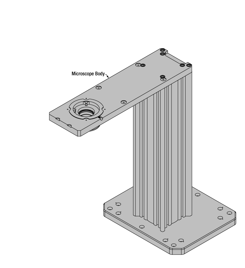
Microscope Body
The microscope body provides the foundation of any Cerna microscope. The support rail utilizes 95 mm rails machined to a high angular tolerance to ensure an aligned optical path and perpendicularity with the optical table. The support rail height chosen (350 - 600 mm) determines the vertical range available for experiments and microscopy components. The 7.74" throat depth, or distance from the optical path to the support rail, provides a large working space for experiments. Components attach to the body by way of either a linear dovetail on the support rail, or a circular dovetail on the epi-illumination arm (on certain models). Please see the Microscope Dovetails tab or here for further details.
 Click to Enlarge
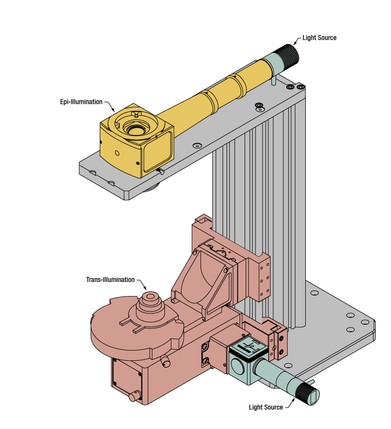
Illumination with a Cerna microscope can come from above (yellow) or below (orange). Illumination sources (green) attach to either.
Illumination
Using the Cerna microscope body, a sample can be illuminated in two directions: from above (epi-illumination, see yellow components to the right) or from below (trans-illumination, see orange components to the right).
Epi-illumination illuminates on the same side of the sample as the viewing apparatus; therefore, the light from the illumination source (green) and the light from the sample plane share a portion of the optical path. It is used in fluorescence, confocal, and reflected light microscopy. Epi-illumination modules, which direct and condition light along the optical path, are attached to the epi-illumination arm of the microscope body via a circular D1N dovetail (see the Microscope Dovetails tab or here for details). Multiple epi-illumination modules are available, as well as breadboard tops, which have regularly spaced tapped holes for custom designs.
Trans-illumination illuminates from the opposite side of the sample as the viewing apparatus. Example imaging modalities include brightfield, differential interference contrast (DIC), Dodt gradient contrast, oblique, and darkfield microscopy. Trans-illumination modules, which condition light (on certain models) and direct it along the optical path, are attached to the support rail of the microscope body via a linear dovetail (see Microscope Dovetails tab or here). Please note that certain imaging modalities will require additional optics to alter the properties of the beam; these optics may be easily incorporated in the optical path via lens tubes and cage systems. In addition, Thorlabs offers condensers, which reshape input collimated light to help create optimal Köhler illumination. These attach to a mounting arm, which holds the condenser at the throat depth, or the distance from the optical path to the support rail. The arm attaches to a focusing module, used for aligning the condenser with respect to the sample and trans-illumination module.
 |
 |
 |
 |
 |
 |
 |
 |
| Epi-Illumination Modules | Breadboards & Body Attachments |
Brightfield | DIC | Dodt | Condensers | Condenser Mounting | Light Sources |
 Click to Enlarge
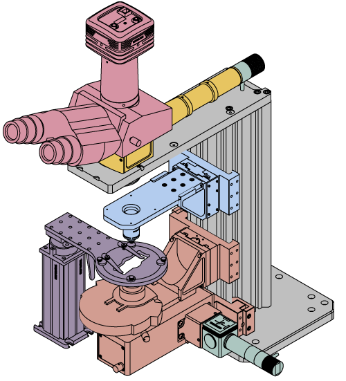
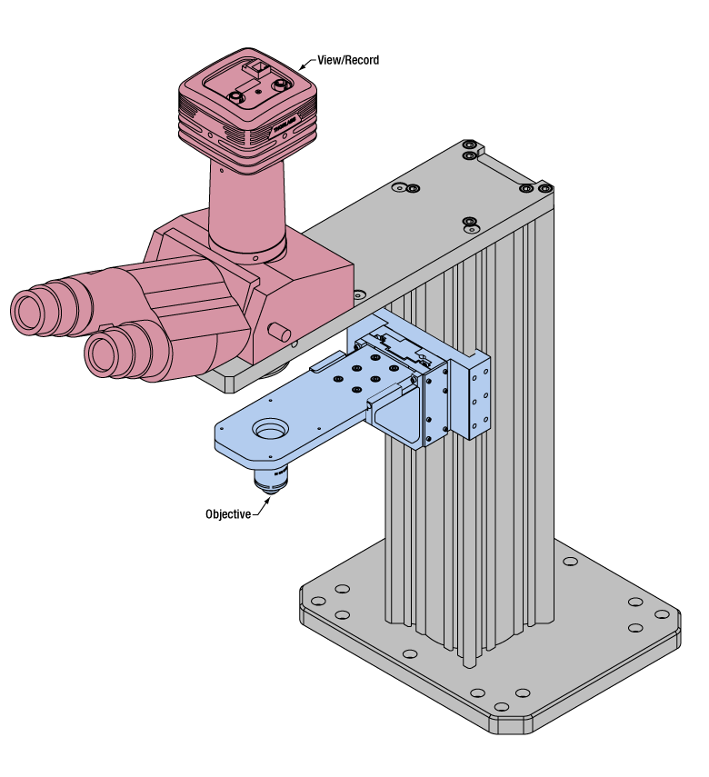
Light from the sample plane is collected through an objective (blue) and viewed using trinocs or other optical ports (pink).
Sample Viewing/Recording
Once illuminated, examining a sample with a microscope requires both focusing on the sample plane (see blue components to the right) and visualizing the resulting image (see pink components).
A microscope objective collects and magnifies light from the sample plane for imaging. On the Cerna microscope, the objective is threaded onto a nosepiece, which holds the objective at the throat depth, or the distance from the optical path to the support rail of the microscope body. This nosepiece is secured to a motorized focusing module, used for focusing the objective as well as for moving it out of the way for sample handling. To ensure a light-tight path from the objective, the microscope body comes with a bellows (not pictured).
Various modules are available for sample viewing and data collection. Trinoculars have three points of vision to view the sample directly as well as with a camera. Double camera ports redirect or split the optical path among two viewing channels. Camera tubes increase or decrease the image magnification. For data collection, Thorlabs offers both cameras and photomultiplier tubes (PMTs), the latter being necessary to detect fluorescence signals for confocal microscopy. Breadboard tops provide functionality for custom-designed data collection setups. Modules are attached to the microscope body via a circular dovetail (see the Microscope Dovetails tab or here for details).


 Click to Enlarge
The rigid stand (purple) pictured is one of various sample mounting options available.
Sample/Experiment Mounting
Various sample and equipment mounting options are available to take advantage of the large working space of this microscope system. Large samples and ancillary equipment can be mounted via mounting platforms, which fit around the microscope body and utilize a breadboard design with regularly spaced tapped through holes. Small samples can be mounted on rigid stands (for example, see the purple component to the right), which have holders for different methods of sample preparation and data collection, such as slides, well plates, and petri dishes. For more traditional sample mounting, slides can also be mounted directly onto the microscope body via a manual XY stage. The rigid stands can translate by way of motorized stages (sold separately), while the mounting platforms contain built-in mechanics for motorized or manual translation. Rigid stands can also be mounted on top of the mounting platforms for independent and synchronized movement of multiple instruments, if you are interested in performing experiments simultaneously during microscopy.
 |
 |
 |
 |
 |
| Translating Platforms | Rigid Stands | Translation Stages for Rigid Stands | Motorized XY Stages | Manual XY Stage |
For sample viewing, Thorlabs offers trinoculars, double camera ports, and camera tubes. Light from the sample plane can be collected via cameras, photomultiplier tubes (PMTs), or custom setups using breadboard tops. Click here for additional information about viewing samples with a Cerna microscope.
| Product Families & Web Presentations | |||
 |
|
 |
 |
| Sample Viewing | Breadboards & Body Attachments |
Cameras | PMTs |
Microscope objectives are held in the optical path of the microscope via a nosepiece. Click here for additional information about viewing a sample with a Cerna microscope.
| Product Families & Web Presentations | ||||
 |
 |
 |
 |
 |
| Objectives | Objective Thread Adapters | Parfocal Length Extender | Piezo Objective Scanner | Objective Mounting |
Large and small experiment mounting options are available to take advantage of the large working space of this microscope. Click here for additional information about mounting a sample for microscopy.
| Product Families & Web Presentations | ||||
|
|
|
|
 |
| Translating Platforms | Rigid Stands | Translation Stages for Rigid Stands | Motorized XY Stages | Manual XY Stage |
Thorlabs offers various light sources for epi- and trans-illumination. Please see the full web presentation of each to determine its functionality within the Cerna microscopy platform.
| Product Families & Web Presentations | ||||
 |
 |
 |
 |
|
| Trans-Illumination Kits | Solis™ High-Power LEDs | Mounted LEDs | X-Cite® Lamps | Other Light Sources |
Epi-illumination illuminates the sample on the same side as the viewing apparatus. Example imaging modalities include fluorescence, confocal, and reflected light microscopy. Click here for additional information on epi-illumination with Cerna.
| Product Families & Web Presentations | ||
|
|
|
| Epi-Illumination | Body Attachments | Light Sources |
Trans-illumination illuminates from the opposite side of the sample as the viewing apparatus. Example imaging modalities include brightfield, differential interference contrast (DIC), Dodt gradient contrast, oblique, and darkfield microscopy. Click here for additional information on trans-illumination with Cerna.
| Product Families & Web Presentations | ||||||
|
|
|
|
 |
|
|
| Brightfield | DIC | Dodt | Condensers | Condenser Mounting | Illumination Kits | Other Light Sources |
The microscope body provides the foundation of any Cerna microscope. The 7.74" throat depth provides a large working space for experiments. Click here for additional information about the Cerna microscope body.
| Product Families & Web Presentations | |
 |
 |
| Microscope Bodies | Microscope Translator |
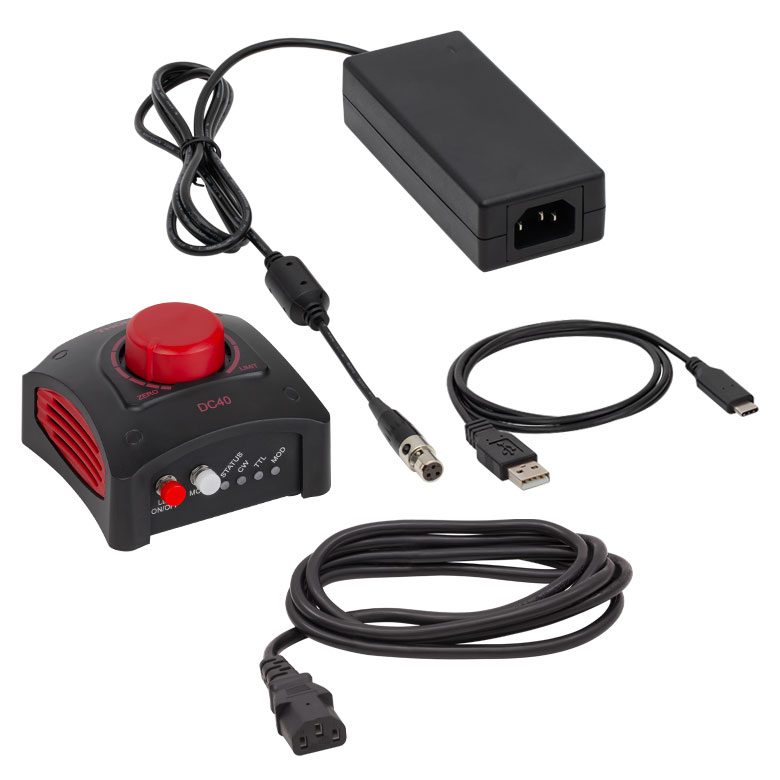
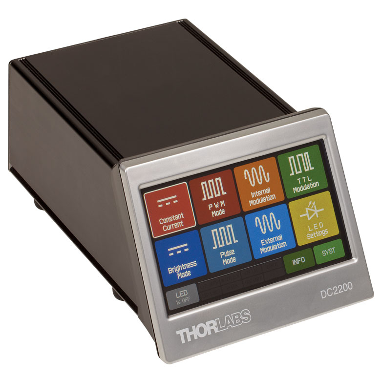
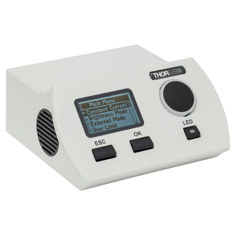
All of the drivers sold here can be used to drive the LEDs included with the above illumination kits. The LEDD1B, DC40, and DC2200 can drive up to one LED at a time, whereas the DC4100 and DC4104 can control up to four LEDs simultaneously by using the DC4100-HUB.
Each controller is capable of modulating the driven LED using an external trigger. For the DC4100 controller, all activated LEDs are controlled by the same modulation signal but can be individually deactivated. For the DC4104 controller, each LED is controlled by a separate modulation signal, all of which are provided through a single, included cable.
Click on the item number link below to view the complete presentation for each controller.
| Compatible Driversa | LEDD1Bb | DC40c | DC2200c | DC4100c,d,e | DC4104c,d,e |
|---|---|---|---|---|---|
| Click Photos to Enlarge |  |
 |
 |
 |
 |
| Main Driver Features | Very Compact Footprint 60 mm x 73 mm x 104 mm (W x H x D) |
Driver Current Up to 4.0 A, Manual and USB-Controlled |
Touchscreen Interface with Internal and External Options for Pulsed and Modulated LED Operation | 4 Channelsd | 4 Channelsd |
| LED Driver Current Output (Max) | 1.2 A | 4.0 Af | LED1 Terminal: 10.0 A LED2 Terminal: 2.0 Ag |
1.0 A per Channel | 1.0 A per Channel |
| LED Driver Forward Voltage (Max) | 12 V | 14.0 Vf | 50 V | 5 V | 5 V |
| Typical Current Noise (RMS) |
- | <1 mA (at 1 A over 2 Ω) | <110 µA (0 to 2 A) <100 µA (0 to 4 A) <200 µA (4 to 10 A) |
~24 µA (400 mA, 2.2 Ω) ~77 µA (1 A, 2.2 Ω) |
~24 µA (400 mA, 2.2 Ω) ~77 µA (1 A, 2.2 Ω) |
| Typical Current Ripple (Peak-to-Peak) |
8 mA | - | - | ~23 mA (400 mA, 2.2 Ω) ~36 mA (1 A, 2.2 Ω) |
~23 mA (400 mA, 2.2 Ω) ~36 mA (1 A, 2.2 Ω) |
| Modulation Frequency Using External Input (Max) | 5 kHz | 5 kHz | 250 kHzh,i | 100 kHzi (Simultaneous Across all Channels) |
100 kHzi (Independently Controlled Channels) |
| External Control Interface(s) | Analog (BNC) | USB 2.0, TTL, and Analog (BNC) | USB 2.0 and Analog (BNC) | USB 2.0 and Analog (BNC) | USB 2.0 and Analog (8-Pin) |
| EEPROM Compatible: Reads Out LED Data for LED Settings | - | ||||
| LCD Display | - | - |

 Zoom
ZoomThe above animation details how filter sets can be added into the DFM1T1 and how the DFM1T1 is then inserted and removed from the DFM1 Filter Cube.
- Empty Kinematic Top for Exchanging User-Provided Filters or Mirror
- Ideal for Quickly Switching Fluorescence Filter Sets in an Aligned Illumination Setup
Additional DFM1T1 inserts allow for different filters to be swapped in and out of our illumination kits. The kinematic design creates a repeatable alignment stop so that the system will not require realignment after the inserts are switched. The animation to the right shows a fluorescence filter set being installed in the DFM1T1.
If any of our imaging filters are ordered at the same time as the DFM1T1, Thorlabs can pre-mount the filters at no additional charge. In order to take advantage of this option, please contact Tech Support prior to ordering.
| Compatible Filters | |||
|---|---|---|---|
| Type | Dimensions | Thickness | |
| Excitation | Ø25 mm | 5 mm | |
| Emission | Ø25 mm | 3.5 mm | |
| Dichroic | Min | 25.0 mm x 35.6 mm | 1.1 mm |
| Max | 25.2 mm x 36.0 mm | 2.0 mm | |