 Products Home / Imaging Components / DIY Cerna Components: Imaging for Home Builders / Microscope Bodies for DIY Cerna® Systems
Microscope Bodies for DIY Cerna® Systems
- Vertical Support Rails for Modular DIY Microscopes
- Holds Cerna® Modules at 7.74" Throat Depth
- Four Rail Heights: 350 mm, 400 mm, 500 mm, and 600 mm
- Microscope Translator Moves Body by 2" in X and Y
MMP2XY
Microscope Body
XY Translator
CEA1500
500 mm Rail Height
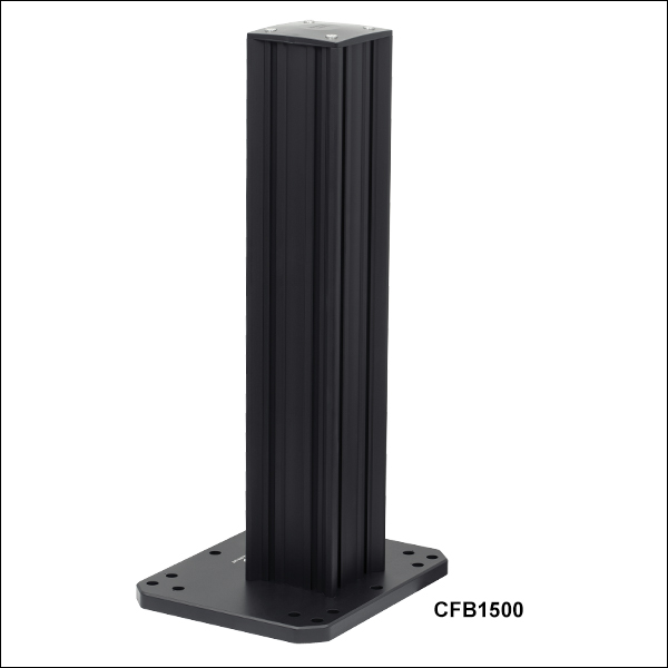
CFB1500
500 mm Rail Height,
No Epi-Illumination Arm
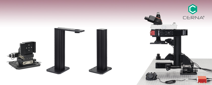
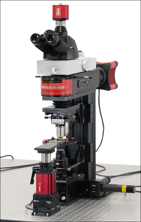
Cerna microscope bodies provide the basic structure for building modular, DIY microscopy setups.
(Microscope for Epi-Fluorescence and Dodt Contrast Shown)


Please Wait
Click to Enlarge
Microscope Designed for Histological Slice Imaging
Features
- 350 mm, 400 mm, 500 mm, or 600 mm Rail Height
- Available with or without Epi-Illumination Arm
- Epi-Illumination Arm has Female D1N Dovetail that Sets 7.74" Throat Depth
- Absence of Epi-Illumination Arm Provides Clearance at Top of Rail
- Linear 95 mm Dovetail Surface Provides Flexible Positioning of Modules Along the Rail
- Microscope Translator Moves Entire Microscope Body over 2" x 2" Square
Click to Enlarge
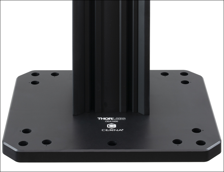
All Cerna Bodies are Engraved with the Cerna Logo and Part Number
DIY Cerna® Microscope Bodies serve as the foundation of fully modular, home-built imaging setups. They primarily consist of a vertical support rail that is available in four heights: 350 mm, 400 mm, 500 mm, and 600 mm. Each side of the rail offers a 95 mm wide dovetail that mates to our microscope modules for DIY Cerna systems. Based upon Thorlabs' 95 mm optical construction rails, these microscope bodies provide stable long-term support and excellent vibrational damping. In addition, they have been precision machined to ensure a high degree of perpendicularity with the workstation.
These microscope bodies are offered with and without epi-illumination arms. Each epi-illumination arm has a female D1N
dovetail on top that accepts our widefield viewing and epi-illumination components. The arm also sets a large throat depth of 7.74", defining an exceptionally large working volume. For applications that would benefit from increased clearance in the plane above the top of the rail, we offer a 500 mm body without the arm. Each body includes a pre-installed mounting base with counterbores spaced for typical imperial and metric tapped hole patterns. This base can be replaced by the MMP2XY Microscope Translator, available below, which translates the microscope body and any attachments over a 2" range in X and Y.
Thorlabs' DIY Cerna platform includes modules that provide objective mounting and condenser mounting , widefield viewing using trinoculars and scientific cameras, sample mounting, and transmitted light imaging using differential interference contrast (DIC), Dodt contrast, and brightfield and oblique illumination. These components mate to each other using a system of dovetails that locks the components in place along the optical path. In addition, our body attachments and extensions integrate DIY Cerna systems with Thorlabs' cage systems and SM-threaded components, enabling fully customizable DIY solutions.
| Thorlabs Dovetail Referencea | |||
|---|---|---|---|
| Type | Shape | Outer Dimension | Angle |
| 95 mm | Linear | 95 mm | 45° |
| D1N | Circular | Ø2.018" | 60° |
| D2Nb | Circular | Ø1.50" | 90° |
| D2NBb | Circular | Ø1.50" | 90° |
| D3N | Circular | Ø45 mm | 70° |
| D5N | Circular | Ø1.58" | 90° |
| D6N | Circular | Ø1.90" | 90° |
| D7N | Circular | Ø2.05" | 90° |
| D8N | Circular | Ø40 mm | 90° |
| D9N | Circular | Ø50 mm | 90° |
| D10N | Circular | Ø52 mm | 90° |
| D1T | Circular | Ø1.50" | 60° |
| D3T | Circular | Ø1.65" | 90° |
| D4T | Circular | Ø1.20" | 90° |
| D1Y | Circular | Ø107 mm | 60° |
| D2Y | Circular | Ø2.32" | 50° |
| D3Y | Circular | Ø1.75" | 90° |
| D4Y | Circular | Ø56 mm | 60° |
| D5Y | Circular | Ø46 mm | 60° |
| D6Y | Circular | Ø41.9 mm | 45° |
| D1Z | Circular | Ø54 mm | 60° |
| D2Z | Circular | Ø57 mm | 60° |
| D3Z | Circular | Ø54 mm | 45° |
Click to Enlarge
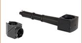
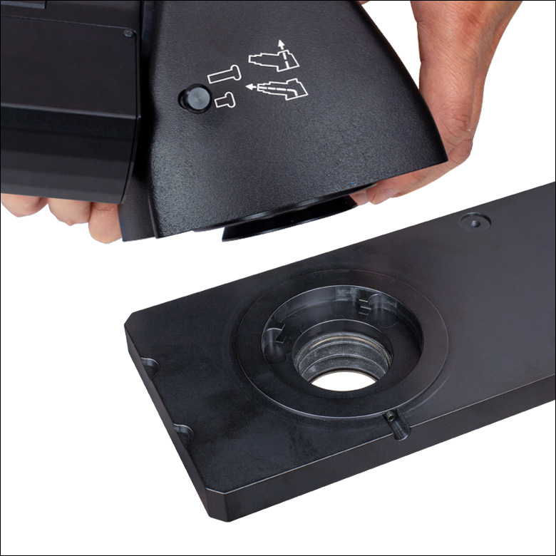
This photo shows the male D1N dovetail on the trinoculars next to the female D1N dovetail on the epi-illumination arm.
Click to Enlarge
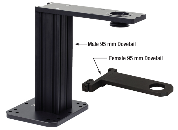
This photo shows the male 95 mm dovetail on the microscope body and the female 95 mm dovetail on the CSA1002 Fixed Arm.
Introduction to Microscope Dovetails
Dovetails are used for mechanical mating and optical port alignment of microscope components. Components are connected by inserting one dovetail into another, then tightening one or more locking setscrews on the female dovetail. Dovetails come in two shapes: linear and circular. Linear dovetails allow the mating components to slide before being locked down, providing flexible positioning options while limiting unneeded degrees of freedom. Circular dovetails align optical ports on different components, maintaining a single optical axis with minimal user intervention.
Thorlabs manufactures many components which use dovetails to mate with our own components or those of other manufacturers. To make it easier to identify dovetail compatibility, we have developed a set of dovetail designations. The naming convention of these designations is used only by Thorlabs and not other microscope manufacturers. The table to the right lists all the dovetails Thorlabs makes, along with their key dimensions.
In the case of Thorlabs’ Cerna® microscopes, different dovetail types are used on different sections of the microscope to ensure that only compatible components can be mated. For example, our WFA2002 Epi-Illuminator Module has a male D1N dovetail that mates with the female D1N dovetail on the microscope body's epi-illumination arm, while the CSS2001 XY Microscopy Stage has a female D1Y dovetail that mates with the male D1Y dovetail on the CSA1051 Mounting Arm.
To learn which dovetail type(s) are on a particular component, consult its mechanical drawing, available by clicking on the red Docs icon ( ) below. For adapters with a female dovetail, the drawing also indicates the size of the hex key needed for the locking setscrew(s). It is important to note that mechanical compatibility does not ensure optical compatibility. Information on optical compatibility is available from Thorlabs' web presentations.
For customers interested in machining their own dovetails, the table to the right gives the outer diameter and angle (as defined by the drawings below) of each Thorlabs dovetail designation. However, the dovetail's height must be determined by the user, and for circular dovetails, the user must also determine the inner diameter and bore diameter. These quantities can vary for dovetails of the same type. One can use the intended mating part to verify compatibility.
In order to reduce wear and simplify connections, dovetails are often machined with chamfers, recesses, and other mechanical features. Some examples of these variations are shown by the drawings below.
Click to Enlarge
Two examples of how circular male dovetails can be manufactured.
Click to Enlarge
Two examples of how circular female dovetails can be manufactured.
Standard Mechanical Interfaces on DIY Cerna® Components
The table below gives the dovetail, optical component threads, and cage system interfaces that are present on each DIY Cerna component. If a DIY Cerna component does not have one of the standard interfaces in the table, it is not listed here. Please note that mechanical compatibility does not ensure optical compatibility. Information on optical compatibility is available from Thorlabs' web presentations.
| Item # | Microscope Dovetails | Optical Component Threadsa | Cage Systemsb | ||||||||||
|---|---|---|---|---|---|---|---|---|---|---|---|---|---|
| 95 mm | D1N | D2N | D2NB | D3N | D5N | D1T | D3T | D1Y | D5Y | Internal | External | ||
| 2CM1 | - | - | - | - | - | - | - | - | - | - | SM1c (1.035"-40) and SM2d (2.035"-40) | SM1c (1.035"-40) | 60 mmd |
| 2CM2 | - | - | - | - | - | - | - | - | - | - | SM1c (1.035"-40) and SM2d (2.035"-40) | SM1c (1.035"-40) | 30 mmc |
| BSA2000e | - | - | - | - | Female | - | - | - | - | - | - | - | - |
| CEA1350 | Male | Female | - | - | - | - | - | - | - | - | - | - | 60 mmd |
| CEA1400 | Male | Female | - | - | - | - | - | - | - | - | - | - | 60 mmd |
| CEA1500 | Male | Female | - | - | - | - | - | - | - | - | - | - | 60 mmd |
| CEA1600 | Male | Female | - | - | - | - | - | - | - | - | - | - | 60 mmd |
| CFB1500 | Male | - | - | - | - | - | - | - | - | - | - | - | - |
| CSA1000 | Female | - | - | - | - | - | - | - | - | - | - | - | - |
| CSA1001 | Female | - | - | - | - | - | - | - | - | - | SM1c (1.035"-40) | - | 30 mmc |
| CSA1002 | Female | - | - | - | - | - | - | - | - | - | SM2d (2.035"-40) | - | 60 mmd |
| CSA1003 | - | Female | - | - | - | - | - | - | - | - | - | - | 60 mmd |
| CSA1051 | Female | - | - | - | - | - | - | - | Male | - | - | - | - |
| CSA1200e,f | - | - | - | - | - | - | - | - | - | - | - | - | 60 mmd |
| CSA1400e | - | - | - | - | - | - | Female | - | - | - | - | - | 60 mmd |
| CSA1500e,g | - | - | - | - | - | - | - | - | - | - | - | - | - |
| CSA2000e | - | - | - | - | Female | - | - | - | - | - | SM2d (2.035"-40) | - | 60 mmd |
| CSA2001 | - | - | - | - | Female | - | - | - | - | - | - | SM2d (2.035"-40) | - |
| CSA2100e | - | - | - | - | - | - | - | - | - | - | SM2d (2.035"-40) | - | 60 mmd |
| CSA3000(/M) | - | Male | - | - | - | - | - | - | - | - | - | - | - |
| CSA3010(/M) | - | Male | - | - | - | - | - | - | - | - | - | - | 30 mmc and 60 mmd |
| Item # | 95 mm | D1N | D2N | D2NB | D3N | D5N | D1T | D3T | D1Y | D5Y | Internal | External | Cage Systems |
| CSC1001 | - | - | - | - | Male | - | - | - | - | - | - | - | - |
| CSC1002 | - | - | - | - | Male | - | - | - | - | - | - | - | - |
| CSC2001 | - | - | - | - | Male | - | - | - | - | - | - | - | - |
| CSD1001 | - | Male & Female | - | Female | - | - | - | - | - | - | - | - | - |
| CSD1002 | - | Male & Female | - | - | - | - | - | - | - | - | - | C-Mounth | - |
| CSE2000 | - | Male & Female | - | - | - | - | - | - | - | - | - | - | 60 mmd |
| CSE2100 | - | Male & Female | - | - | - | - | - | Female | - | - | SM1c (1.035"-40) | - | 30 mmc and 60 mmd |
| CSE2200 | - | Male & Female | - | - | - | - | - | Female | - | - | SM1c (1.035"-40) | - | 30 mmc and 60 mmd |
| CSN100e | - | - | - | - | - | - | - | - | - | - | M32 x 0.75 | - | 60 mmd |
| CSN110 | - | - | - | - | - | - | Male | - | - | - | M32 x 0.75 | - | 30 mmc and 60 mmd |
| CSNK10 | - | - | - | - | - | - | - | - | - | - | M32 x 0.75 | - | 60 mmd |
| CSNK100e | - | - | - | - | - | - | - | - | - | - | M32 x 0.75 | - | 60 mmd |
| CSN200 | - | - | - | - | - | - | Male | - | - | - | M32 x 0.75 | - | - |
| CSN210 | - | - | - | - | - | - | Male | - | - | - | M32 x 0.75 | - | - |
| CSN1201f | - | - | - | - | - | - | - | - | - | - | M32 x 0.75 | - | - |
| CSN1202f | - | - | - | - | - | - | - | - | - | - | M25 x 0.75 | - | - |
| CSS2001 | - | - | - | - | - | - | - | - | Female | - | - | - | - |
| LAURE1 | - | Male | Female | - | - | - | - | - | - | - | - | - | - |
| LAURE2 | - | Male | Female | - | - | - | - | - | - | - | - | - | - |
| LCPN1 | - | - | - | - | Male | - | - | - | - | - | SM30 (M30.5 x 0.5) | - | 30 mmc and 60 mmd |
| LCPN2 | - | Male | - | - | - | - | - | - | - | - | SM30 (M30.5 x 0.5) | - | 30 mmc and 60 mmd |
| Item # | 95 mm | D1N | D2N | D2NB | D3N | D5N | D1T | D3T | D1Y | D5Y | Internal | External | Cage Systems |
| LCPN3 | - | Male | - | - | - | - | - | - | - | Female | SM30 (M30.5 x 0.5) | - | 60 mmd |
| LCPN4 | - | Male | - | - | - | - | - | - | - | - | SM2d (2.035"-40) | - | 60 mmd |
| LCPN5 | - | - | - | - | Male | - | - | - | - | - | SM2d (2.035"-40) | - | 60 mmd |
| LCPN6 | - | - | Female | - | - | - | - | - | - | - | SM1c (1.035"-40) | - | 30 mmc and 60 mmd |
| LCPY2 | - | - | - | - | - | - | - | - | - | Male | SM30 (M30.5 x 0.5) | - | 30 mmc and 60 mmd |
| LCPY3 | - | - | - | - | - | - | - | - | - | Female | - | - | 30 mmc and 60 mmd |
| OPX2400(/M) | - | Male & Female | - | - | - | - | - | - | - | - | SM2d (2.035"-40) | - | 60 mmd |
| SM1A70 | - | - | - | - | - | - | - | - | - | - | SM30 (M30.5 x 0.5) | SM1c (1.035"-40) | - |
| SM1A58 | - | - | Male | Male | - | - | - | - | - | - | SM1c (1.035"-40) | SM2d (2.035"-40) | 30 mmc |
| SM2A56 | - | - | - | - | - | - | - | Male | - | - | - | SM2d (2.035"-40) | - |
| SM2A59 | - | Male | - | - | - | - | - | - | - | - | SM2d (2.035"-40) | - | - |
| TC1X | - | - | Male | - | - | - | - | - | - | - | - | - | - |
| WFA0150 | Female | - | - | - | - | - | - | - | - | - | - | - | - |
| WFA1000 | - | - | - | - | - | - | - | - | - | - | - | - | 30 mmc |
| WFA1010 | - | - | - | - | - | - | - | - | - | - | SM1c (1.035"-40) | - | 30 mmc |
| WFA1020 | - | - | - | - | - | - | - | - | - | - | SM1c (1.035"-40) | - | 30 mmc |
| WFA1051 | - | - | - | - | - | - | - | - | - | - | SM1c (1.035"-40) | - | 30 mmc |
| WFA1100 | - | - | - | - | - | - | - | - | - | - | - | - | 30 mmc |
| WFA2001 | - | Male & Female | - | - | - | - | - | - | - | - | SM1c (1.035"-40) | SM1c (1.035"-40) | - |
| WFA2002 | - | Male & Female | - | - | - | - | - | - | - | - | SM1c (1.035"-40) | - | 30 mmc |
| Item # | 95 mm | D1N | D2N | D2NB | D3N | D5N | D1T | D3T | D1Y | D5Y | Internal | External | Cage Systems |
| WFA4100 | - | Male | - | - | - | - | - | - | - | - | SM1c (1.035"-40) | C-Mounth | - |
| WFA4101 | - | Male | - | - | - | - | - | - | - | - | SM1c (1.035"-40) | C-Mounth | - |
| WFA4102 | - | Male | - | - | - | - | - | - | - | - | SM1c (1.035"-40) | C-Mounth | - |
| WFA4111 | - | Male | - | - | - | - | - | - | - | - | - | SM2d (2.035"-40) | - |
| WFA4112 | - | - | - | Male | - | - | - | - | - | - | - | C-Mounth | - |
| Female | - | - | - | - | - | - | - | - | - | - | - | - | |
| Female | - | - | - | - | - | - | - | - | - | - | - | - | |
| Female | - | - | - | - | - | - | - | - | - | - | - | - | |
| Female | - | - | - | - | - | - | - | - | - | - | - | - | |
| XT95P12(/M) | Female | - | - | - | - | - | - | - | - | - | - | - | - |
| ZFM1020 | Female | - | - | - | - | - | - | - | - | - | - | - | - |
| ZFM1030 | Female | - | - | - | - | - | - | - | - | - | - | - | - |
| ZFM2020 | Female | - | - | - | - | - | - | - | - | - | - | - | - |
| ZFM2030 | Female | - | - | - | - | - | - | - | - | - | - | - | - |
Building a Cerna® Microscope
The Cerna microscopy platform's large working volume and system of dovetails make it straightforward to connect and position the components of the microscope. This flexibility enables simple and stable set up of a preconfigured microscope, and provides easy paths for later upgrades and modification. See below for a couple examples of the assembly of some DIY Cerna microscopes.
DIY Cerna Design and Assembly
Walkthrough of a DIY Microscope Configuration
This DIY microscope uses a CSA3000(/M) Breadboard Top, a CSA2001 Dovetail Adapter, our CSA1001 and CSA1002 Fixed Arms, and other body attachments and extensions. These components provide interfaces to our lens tube and cage construction systems, allowing the rig to incorporate two independent trans-illumination modules, a home-built epi-illumination path, and a custom sample viewing optical path.
The simplicity of Thorlabs optomechanical interfaces allows a custom DIY microscope to be quickly assembled and reconfigured for custom imaging applications.
| Posted Comments: | |
| No Comments Posted |
Click on the different parts of the microscope to explore their functions.
Elements of a Microscope
This overview was developed to provide a general understanding of a Cerna® microscope. Click on the different portions of the microscope graphic to the right or use the links below to learn how a Cerna microscope visualizes a sample.
Terminology
Arm: Holds components in the optical path of the microscope.
Bayonet Mount: A form of mechanical attachment with tabs on the male end that fit into L-shaped slots on the female end.
Bellows: A tube with accordion-shaped rubber sides for a flexible, light-tight extension between the microscope body and the objective.
Breadboard: A flat structure with regularly spaced tapped holes for DIY construction.
Dovetail: A form of mechanical attachment for many microscopy components. A linear dovetail allows flexible positioning along one dimension before being locked down, while a circular dovetail secures the component in one position. See the Microscope Dovetails tab or here for details.
Epi-Illumination: Illumination on the same side of the sample as the viewing apparatus. Epi-fluorescence, reflected light, and confocal microscopy are some examples of imaging modalities that utilize epi-illumination.
Filter Cube: A cube that holds filters and other optical elements at the correct orientations for microscopy. For example, filter cubes are essential for fluorescence microscopy and reflected light microscopy.
Köhler Illumination: A method of illumination that utilizes various optical elements to defocus and flatten the intensity of light across the field of view in the sample plane. A condenser and light collimator are necessary for this technique.
Nosepiece: A type of arm used to hold the microscope objective in the optical path of the microscope.
Optical Path: The path light follows through the microscope.
Rail Height: The height of the support rail of the microscope body.
Throat Depth: The distance from the vertical portion of the optical path to the edge of the support rail of the microscope body. The size of the throat depth, along with the working height, determine the working space available for microscopy.
Trans-Illumination: Illumination on the opposite side of the sample as the viewing apparatus. Brightfield, differential interference contrast (DIC), Dodt gradient contrast, and darkfield microscopy are some examples of imaging modalities that utilize trans-illumination.
Working Height: The height of the support rail of the microscope body plus the height of the base. The size of the working height, along with the throat depth, determine the working space available for microscopy.
 Click to Enlarge
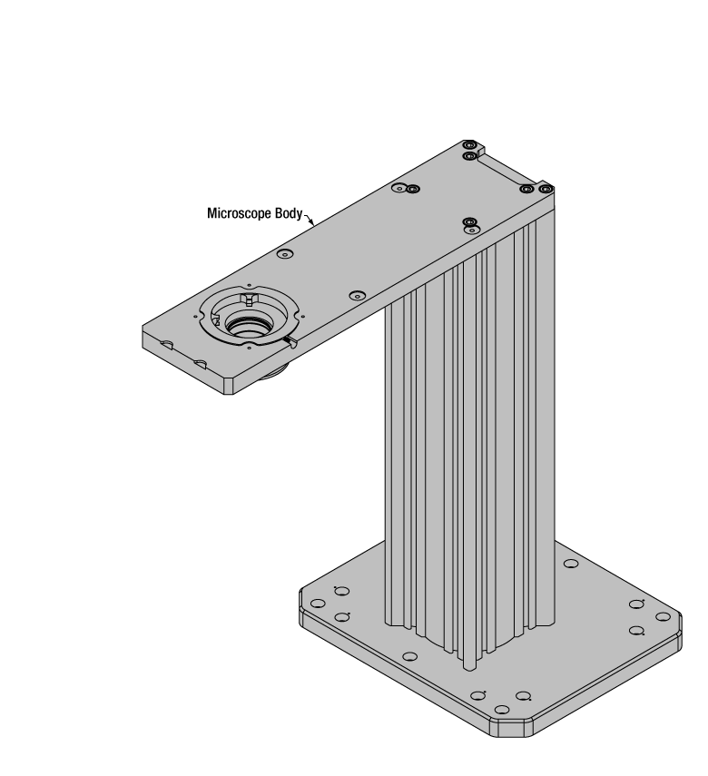
Cerna Microscope Body
Click to Enlarge
Body Details
Microscope Body
The microscope body provides the foundation of any Cerna microscope. The support rail utilizes 95 mm rails machined to a high angular tolerance to ensure an aligned optical path and perpendicularity with the optical table. The support rail height chosen (350 - 600 mm) determines the vertical range available for experiments and microscopy components. The 7.74" throat depth, or distance from the optical path to the support rail, provides a large working space for experiments. Components attach to the body by way of either a linear dovetail on the support rail, or a circular dovetail on the epi-illumination arm (on certain models). Please see the Microscope Dovetails tab or here for further details.
 Click to Enlarge
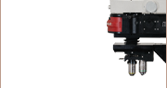
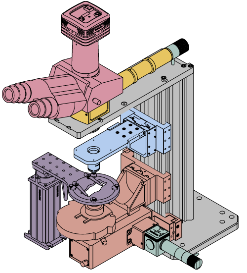
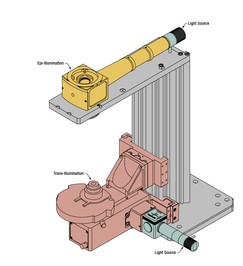
Illumination with a Cerna microscope can come from above (yellow) or below (orange). Illumination sources (green) attach to either.
Illumination
Using the Cerna microscope body, a sample can be illuminated in two directions: from above (epi-illumination, see yellow components to the right) or from below (trans-illumination, see orange components to the right).
Epi-illumination illuminates on the same side of the sample as the viewing apparatus; therefore, the light from the illumination source (green) and the light from the sample plane share a portion of the optical path. It is used in fluorescence, confocal, and reflected light microscopy. Epi-illumination modules, which direct and condition light along the optical path, are attached to the epi-illumination arm of the microscope body via a circular D1N dovetail (see the Microscope Dovetails tab or here for details). Multiple epi-illumination modules are available, as well as breadboard tops, which have regularly spaced tapped holes for custom designs.
Trans-illumination illuminates from the opposite side of the sample as the viewing apparatus. Example imaging modalities include brightfield, differential interference contrast (DIC), Dodt gradient contrast, oblique, and darkfield microscopy. Trans-illumination modules, which condition light (on certain models) and direct it along the optical path, are attached to the support rail of the microscope body via a linear dovetail (see Microscope Dovetails tab or here). Please note that certain imaging modalities will require additional optics to alter the properties of the beam; these optics may be easily incorporated in the optical path via lens tubes and cage systems. In addition, Thorlabs offers condensers, which reshape input collimated light to help create optimal Köhler illumination. These attach to a mounting arm, which holds the condenser at the throat depth, or the distance from the optical path to the support rail. The arm attaches to a focusing module, used for aligning the condenser with respect to the sample and trans-illumination module.
 |
 |
 |
 |
 |
 |
 |
 |
| Epi-Illumination Modules | Breadboards & Body Attachments |
Brightfield | DIC | Dodt | Condensers | Condenser Mounting | Light Sources |
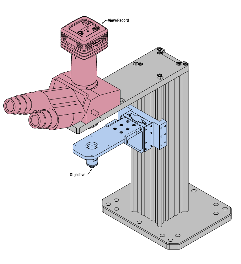 Click to Enlarge
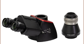
Light from the sample plane is collected through an objective (blue) and viewed using trinocs or other optical ports (pink).
Sample Viewing/Recording
Once illuminated, examining a sample with a microscope requires both focusing on the sample plane (see blue components to the right) and visualizing the resulting image (see pink components).
A microscope objective collects and magnifies light from the sample plane for imaging. On the Cerna microscope, the objective is threaded onto a nosepiece, which holds the objective at the throat depth, or the distance from the optical path to the support rail of the microscope body. This nosepiece is secured to a motorized focusing module, used for focusing the objective as well as for moving it out of the way for sample handling. To ensure a light-tight path from the objective, the microscope body comes with a bellows (not pictured).
Various modules are available for sample viewing and data collection. Trinoculars have three points of vision to view the sample directly as well as with a camera. Double camera ports redirect or split the optical path among two viewing channels. Camera tubes increase or decrease the image magnification. For data collection, Thorlabs offers both cameras and photomultiplier tubes (PMTs), the latter being necessary to detect fluorescence signals for confocal microscopy. Breadboard tops provide functionality for custom-designed data collection setups. Modules are attached to the microscope body via a circular dovetail (see the Microscope Dovetails tab or here for details).


 Click to Enlarge
The rigid stand (purple) pictured is one of various sample mounting options available.
Sample/Experiment Mounting
Various sample and equipment mounting options are available to take advantage of the large working space of this microscope system. Large samples and ancillary equipment can be mounted via mounting platforms, which fit around the microscope body and utilize a breadboard design with regularly spaced tapped through holes. Small samples can be mounted on rigid stands (for example, see the purple component to the right), which have holders for different methods of sample preparation and data collection, such as slides, well plates, and petri dishes. For more traditional sample mounting, slides can also be mounted directly onto the microscope body via a manual XY stage. The rigid stands can translate by way of motorized stages (sold separately), while the mounting platforms contain built-in mechanics for motorized or manual translation. Rigid stands can also be mounted on top of the mounting platforms for independent and synchronized movement of multiple instruments, if you are interested in performing experiments simultaneously during microscopy.
 |
 |
 |
 |
 |
| Translating Platforms | Rigid Stands | Translation Stages for Rigid Stands | Motorized XY Stages | Manual XY Stage |
For sample viewing, Thorlabs offers trinoculars, double camera ports, and camera tubes. Light from the sample plane can be collected via cameras, photomultiplier tubes (PMTs), or custom setups using breadboard tops. Click here for additional information about viewing samples with a Cerna microscope.
| Product Families & Web Presentations | |||
 |
|
 |
 |
| Sample Viewing | Breadboards & Body Attachments |
Cameras | PMTs |
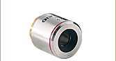
Microscope objectives are held in the optical path of the microscope via a nosepiece. Click here for additional information about viewing a sample with a Cerna microscope.
| Product Families & Web Presentations | ||||
 |
 |
 |
 |
 |
| Objectives | Objective Thread Adapters | Parfocal Length Extender | Piezo Objective Scanner | Objective Mounting |
Large and small experiment mounting options are available to take advantage of the large working space of this microscope. Click here for additional information about mounting a sample for microscopy.
| Product Families & Web Presentations | ||||
|
|
|
|
 |
| Translating Platforms | Rigid Stands | Translation Stages for Rigid Stands | Motorized XY Stages | Manual XY Stage |
Thorlabs offers various light sources for epi- and trans-illumination. Please see the full web presentation of each to determine its functionality within the Cerna microscopy platform.
| Product Families & Web Presentations | ||||
 |
 |
 |
 |
|
| Trans-Illumination Kits | Solis™ High-Power LEDs | Mounted LEDs | X-Cite® Lamps | Other Light Sources |
Epi-illumination illuminates the sample on the same side as the viewing apparatus. Example imaging modalities include fluorescence, confocal, and reflected light microscopy. Click here for additional information on epi-illumination with Cerna.
| Product Families & Web Presentations | ||
|
|
|
| Epi-Illumination | Body Attachments | Light Sources |
Trans-illumination illuminates from the opposite side of the sample as the viewing apparatus. Example imaging modalities include brightfield, differential interference contrast (DIC), Dodt gradient contrast, oblique, and darkfield microscopy. Click here for additional information on trans-illumination with Cerna.
| Product Families & Web Presentations | ||||||
|
|
|
|
 |
|
|
| Brightfield | DIC | Dodt | Condensers | Condenser Mounting | Illumination Kits | Other Light Sources |
The microscope body provides the foundation of any Cerna microscope. The 7.74" throat depth provides a large working space for experiments. Click here for additional information about the Cerna microscope body.
| Product Families & Web Presentations | |
 |
 |
| Microscope Bodies | Microscope Translator |

 Zoom
ZoomClick to Enlarge
Refer to the Table Below for Available Working Heights and Rail Heights
Click to Enlarge
Female D1N Dovetail in Epi-Illumination Arm Accepts Male D1N Dovetail Components
- 350 mm, 400 mm, 500 mm, or 600 mm Rail Height
- Linear 95 mm Dovetail for Flexible Positioning of Microscope Modules
- Includes Epi-Illumination Arm
- Structural Support for Widefield Viewing, Epi-Illumination, and Custom Modules
- Female D1N Dovetail at 7.74" Throat Depth
- Four 4-40 Taps for 60 mm Cage System on Bottom
- Magnetic Bellows Creates Light-Tight Beam Path to Objective Holder
- Mounting Base with 1/4" and M6 Counterbores for Imperial and Metric Workstations
| Item # | Rail Height | Working Height | Weight |
|---|---|---|---|
| CEA1350 | 350 mm (13.78") | 365.9 mm (14.40") | 13.75 kg (30.25 lbs) |
| CEA1400 | 400 mm (15.75") | 415.9 mm (16.37") | 14.55 kg (32.01 lbs) |
| CEA1500 | 500 mm (19.69") | 515.9 mm (20.31") | 16.15 kg (35.53 lbs) |
| CEA1600 | 600 mm (23.62") | 615.9 mm (24.24") | 17.80 kg (39.16 lbs) |
Microscope bodies with epi-illumination arms provide a large working volume for DIY setups. The vertical rail has a linear 95 mm dovetail surface for mounting user-built and pre-built microscope modules, and the epi-illumination arm defines a large 7.74" throat depth.
These microscope bodies are offered in four rail heights ranging from 350 mm to 600 mm. Shorter heights offer better access to the top of the microscope, making it easier to use trinoculars or build widefield viewing, epi-illumination, and laser scanning pathways. In contrast, taller heights provide additional space along the vertical rail for designing optical paths using our body attachments and extensions, objective mounting and condenser mounting accessories, or trans-illumination modules for DIC imaging, Dodt contrast, or brightfield and oblique illumination. This rail also accepts the mounting brackets for our Manual XY Stage and Fast XY Scanning Stage sample holders.
The top of the epi-illumination arm has a female D1N dovetail at the 7.74" throat depth, while the bottom of the epi-illumination arm has four 4-40 taps for our 60 mm cage system and a magnetic bellows that creates a light-tight beam path to DIY Cerna objective holders. This bellows can be adjusted from 0.40" to 2.00" long. We offer a range of male D1N dovetail adapters and breadboard tops that can be mated to the female D1N dovetail, which confer compatibility with Thorlabs' SM-threaded components, cage systems, and complete range of optomechanics.
Please note that at 350 mm tall, the CEA1350 Microscope Body does not have enough room for DIC imaging setups and leaves only limited room for Dodt contrast and brightfield illumination.

 Zoom
Zoom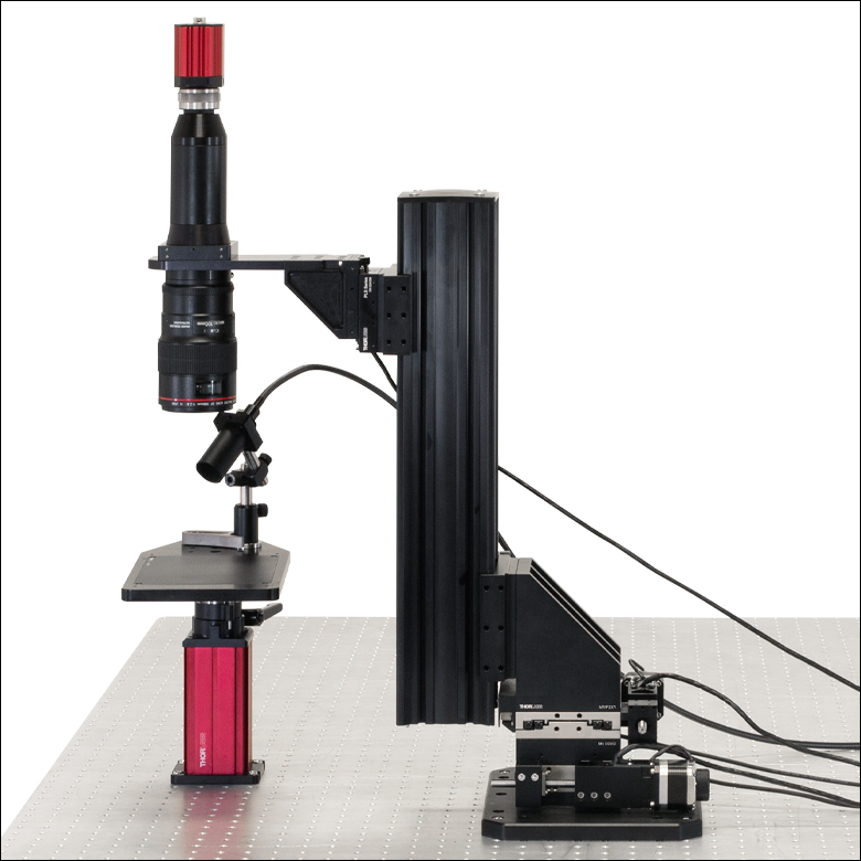
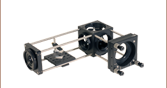
Click to Enlarge
The absence of the epi-illumination arm creates additional space above the macro lens in this functional imaging setup.
Click to Enlarge
CFB1500 Mechanical Drawing
| Item # | Rail Height | Weight |
|---|---|---|
| CFB1500 | 500 mm (19.69") | 13.20 kg (29.04 lbs) |
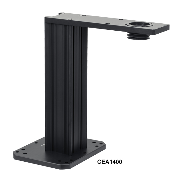
- 500 mm Rail Height
- Linear 95 mm Dovetail for Flexible Positioning of Microscope Modules
- Absence of Epi-Illumination Arm Creates Additional Clearance Above the Top of the Rail
- Mounting Base with 1/4" and M6 Counterbores for Imperial and Metric Workstations
The CFB1500 Microscope Body is offered without an epi-illumination arm for DIY setups that require added clearance in the region above the top of the vertical support rail. It is ideal for applications such as intrinsic imaging, in which it is necessary to mount a tall optical assembly directly above the specimen, as shown in the image to the right. It also provides greater versatility in setups where the epi-illumination arm is not needed.
This microscope body has a 500 mm rail height and the same linear 95 mm dovetail surface as the microscope bodies sold above.

 Zoom
Zoom| Specifications | |
|---|---|
| Number of Axes | Two |
| Travel Range per Axis | 2" (50.8 mm) |
| Bearings | Crossed Roller |
| XY Orthogonality | <2.4 mrad |
| Angular Deviation | Pitch: <350 µrad (Max) Yaw: <150 µrad (Max) |
| Encoder Resolution | 0.5 µm |
| Bidirectional Repeatability | ±1 µm |
| Backlash | 0.185 µm |
| Minimum Achievable Incremental Movement | 1 µm |
| Minimum Repeatable Incremental Movement | 1.002 µm |
| Speed (Max)a | 3.96 mm/sec |
| Maximum Acceleration | 58.2 mm/sec2 |
| Load Capacity When Mounted Horizontally |
≤75 lbs (34.0 kg) |
| Motor & Encoder Cable Length | 9.8' (3 m) |
| Weight | 26.9 lbs (12.2 kg) |
| Dimensions (L x W x H) | 10.29" x 8.92" x 9.31" (261.4 mm x 226.6 mm x 236.5 mm) |
| Recommended Controller | MCM301 |

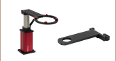
Click to Enlarge
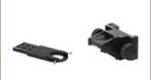
The MMP2XY Translator can provide XY translation for a home-built imaging rig. The PLSZ Focusing Module provides Z-axis adjustments for the optical system. One MCM301 Controller can drive all three axes.
- Motorized Translation of Entire Microscope Body Over 2" Range in X and Y
- Fits Behind Support Rail, Leaving Rest of Workstation Free
- Moving the Microscope Body Lets Sensitive Samples Remain Stationary
- Requires MCM301 3-Axis Controller (Sold Separately Below)
Thorlabs' MMP2XY Microscope Translator is ideal for applications that require the field of view to translate without disturbing a specimen. The microscope translator is constructed using two high-performance linear stages that incorporate stepper motor actuators. Each stepper motor has a 2" travel range and 0.5 µm encoder resolution. The motors can be driven using the MCM301 3-Axis Controller sold below, which enables fine, variable-speed motorized travel.
| Microscope Body Item # |
Weight of Microscope Body without Mounting Basea |
|---|---|
| CEA1350 | 11.59 kg (25.50 lbs) |
| CEA1400 | 12.39 kg (27.26 lbs) |
| CEA1500 | 13.99 kg (30.78 lbs) |
| CEA1600 | 15.64 kg (34.41 lbs) |
| CFB1500 | 11.04 kg (24.29 lbs) |
To secure the translator to the microscope body, simply unscrew the mounting base included with the body, position the microscope within the translator's 95 mm dovetail as desired, then tighten the three side-located 4 mm hex setscrews on the dovetail clamp. As shown by the photo to the upper right, when the translator is secured in place, it will be conveniently located behind the microscope body and away from the optical path and experimental setups. Please note that the MMP2XY should be attached to the tabletop before the microscope body is secured to the translator. Imperial and metric hardware is included for mounting the translator to an optical table.
The microscope translator can support a maximum load of 75 lbs (34.0 kg). When attaching a Cerna microscope body, some of this load capacity will be consumed by the vertical support rail and the epi-illumination arm (if present). To help determine how much load capacity will remain after mounting the body, the weights of our Cerna microscope bodies without their pre-installed mounting bases are given in the table to the left.

 Zoom
Zoom| Compatible Stages |
|---|
| Translation Stages for Rigid Stands |
| Motorized Vertical Rigid Stand |
| Motorized Translating Breadboard |
| Microscope Body Translator |
| Motorized Focusing Module |
| Controller Specifications |
|---|
| Compatible Motor Specifications |
|---|
Software
Version 1.2 (August 5, 2024)
The software package contains the installation files
for the GUI interface, driver, and SDK. The software was verified with Windows® 10 (64-bit) and Windows® 11 (64-bit).
- Designed for Cerna Components with Stepper Motors
- Provides Control for up to Three Axes
- Separately Available Joystick Allows Hand Operation
- Each Axis can be Individually Disabled to Prevent Unintended Movements or to Retain a Position
- Remotely Control Translation Using Standalone Software (Requires 64-Bit Windows® 7 or Later)
The MCM301 3-Axis Controller is designed for use with the Thorlabs components listed in the table to the right. The MCMK3 3-Knob Joystick, available separately, can be connected to provide hand-operation. The controller can also be operated remotely using standalone software.
When using the optional MCMK3 joystick, each side face of the joystick includes a rotating knob and a push-button switch that are dedicated to a single axis. The push-button switch on the joystick enables and disables the axis and is lit in green when the axis is enabled. Disabling the axis lets the user preserve a position or prevent accidental movements. A dial on the top face adjusts the velocity per rotation of the knobs. For more information on the MCMK3 joystick and how to utilize the USB HID protocol, please see the full web presentation.
Since each MCM301 controller has three channels, you only need to purchase enough channels for each of the modules you intend to drive. For example, a Cerna microscope equipped with a PMP2XY Translating Platform (which has two axes) only requires one MCM301 controller.
For more information, as well as compatible software and a LabVIEW™/C++/Python SDK, please see the full web presentation for the MCM301 controller.