Products Home
Piezo Objective Scanner
- Enables Objective Positioning and Z-Stack Acquisition with Resolution Down to 1 nm
- Travel Range: 600 µm ± 10% in Open Loop; 450 µm in Closed Loop
- Support for Heavy Objectives Up to 500 g
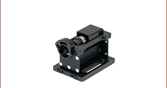
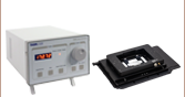
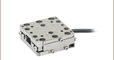
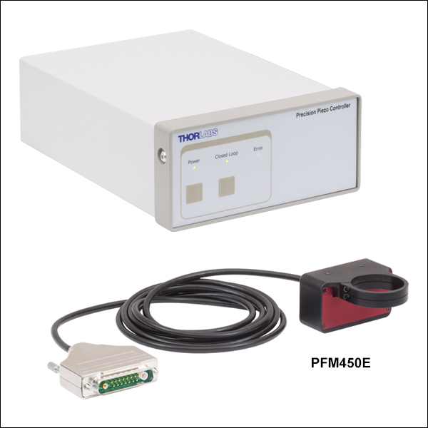
PFM450E
Piezo Objective Scanner and Paired Controller
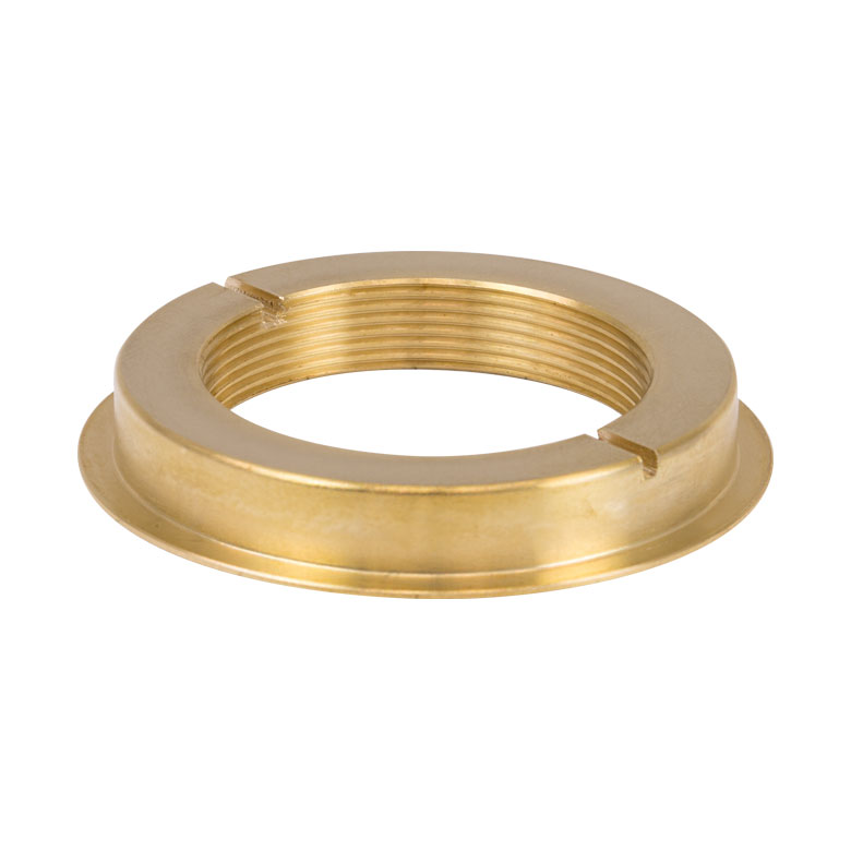
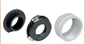
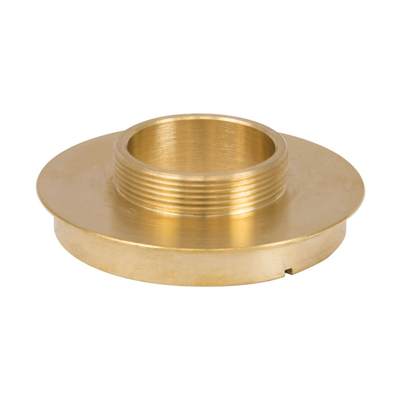
PFMA01
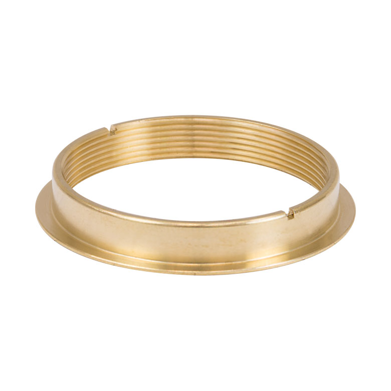
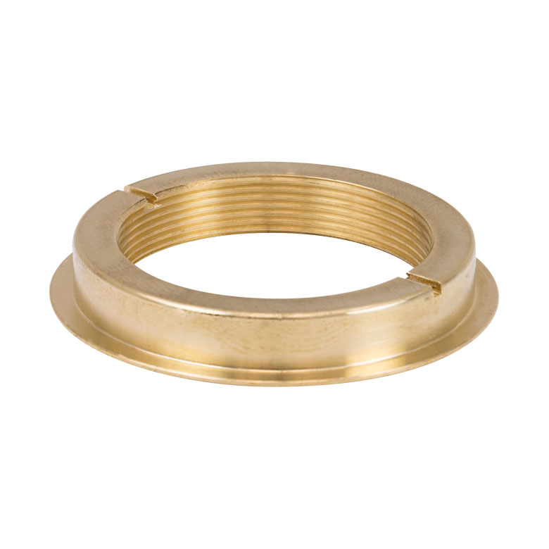
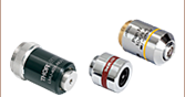
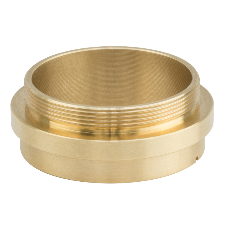
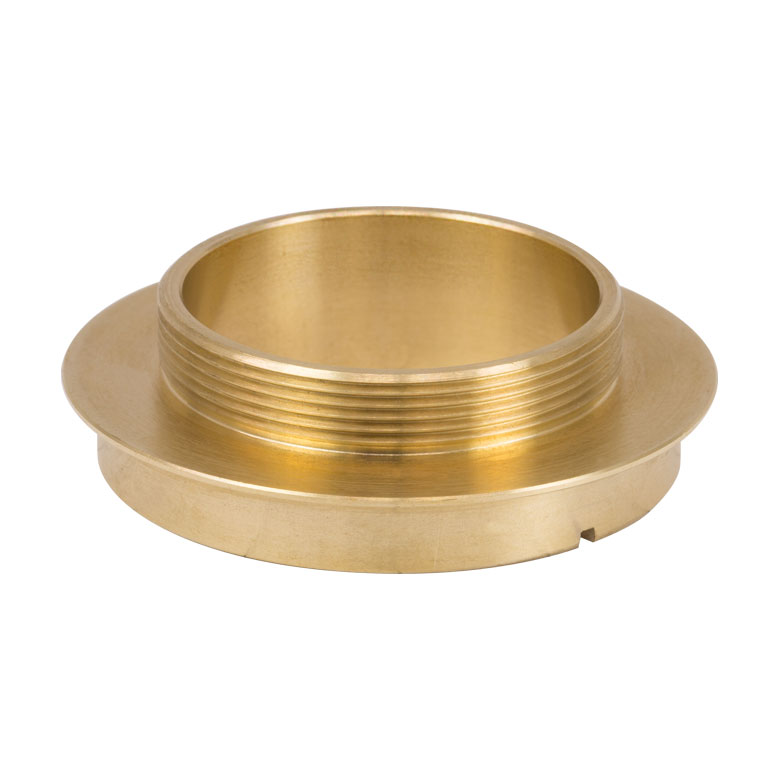
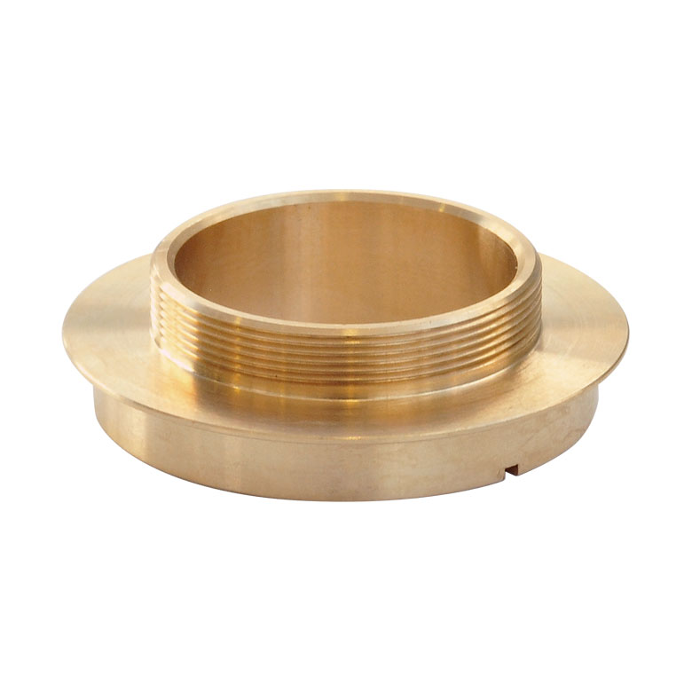
M32 x 0.75 Microscope Adapter
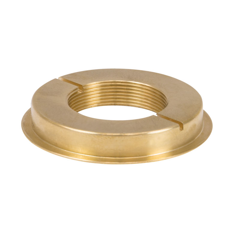
PFMA02
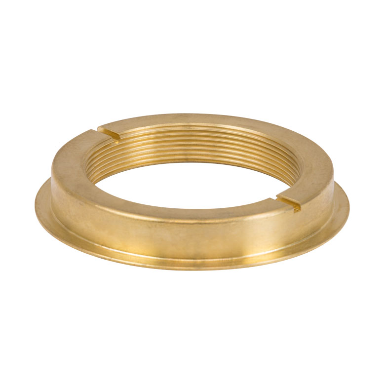
M32 x 0.75 Objective Adapter


Please Wait
Click for Details
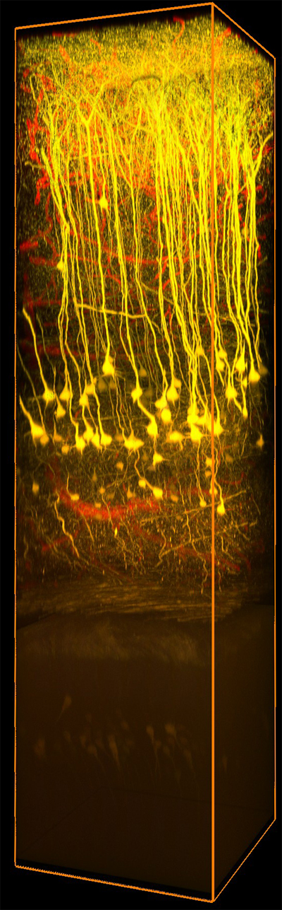
Deep Brain Image Captured with a Bergamo Microscope Equipped with a PFM450E Piezo Objective Scanner (Courtesy of RIKEN Brain Science Institute, Wako, Japan.)
Applications
- Autofocus System for High Speed Time-Lapse and
Z-Stack Imaging - Optical Sectioning for 3D Imaging
- Fine Focus Adjustment
- Scanning Interferometry
- Surface Profilometry and Analysis
- Semiconductor and Wafer Inspection
Click to Enlarge
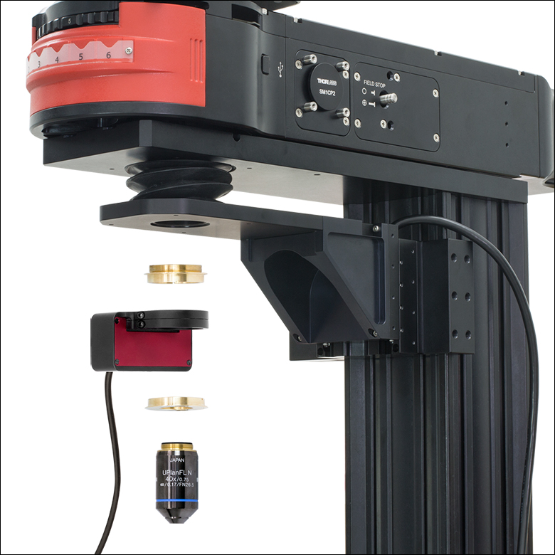
Exploded View
Click to Enlarge
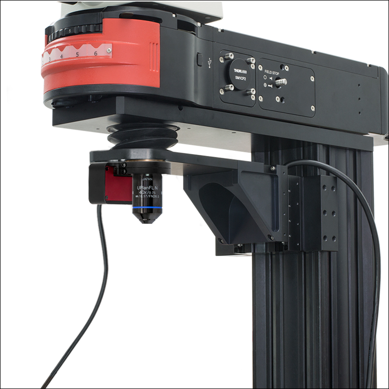
Assembled View
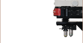
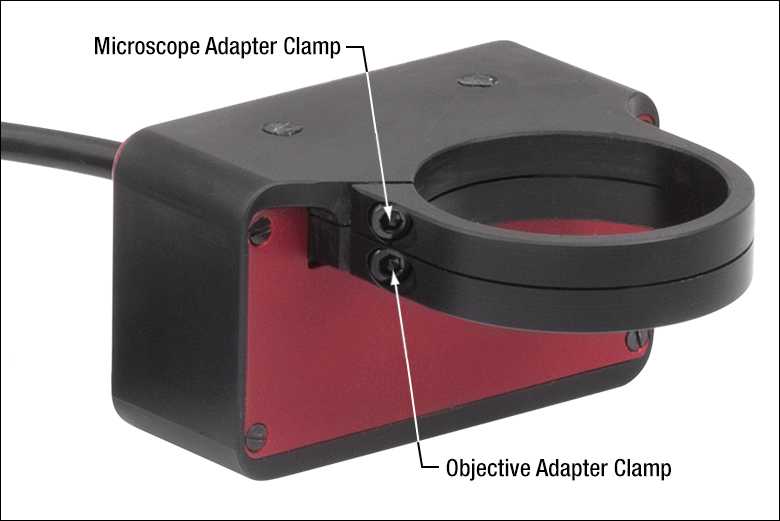
The scanner is installed by threading a brass adapter into the microscope's objective holder with the included spanner wrench and tightening a flexure clamp around the adapter with the included 5/64" (2 mm) hex key. The objective is attached to the scanner using a separate brass adapter and flexure clamp.
Features
- Fast Acquisitions and High Frame Rates Enabled by 25 ms Typical Settling Time
- Maximum Clear Aperture of Ø29.0 mm Supports Large-Field-of-View Objectives
- Capacitive Feedback Sensors Provide Resolution Down to 1 nm and Help User Actively Compensate for Drift
- Quick-Release Flexure Clamps Allow Fast Objective Exchange
- Compatible with Upright, Inverted, and Rotating Microscopes
- Standalone Kinesis® Interface, ThorImage®LS Integration, and Control via External Voltage
- Software Permits Easy Tuning for Different Objective Weights
The PFM450E Piezo Objective Positioner is designed for fine focus adjustment and high-speed Z-stack acquisition. Engineered for compatibility with Thorlabs' Bergamo® III Multiphoton Microscopes, our Confocal Imaging System, our Cerna® Microscopy Platform, and third-party microscopes, it bypasses the relatively slow stepper motors built into microscopes in order to quickly obtain scans of 3D volumes. Built-in capacitive feedback sensors allow the module to provide 1 nm resolution in open-loop operation and 3 nm resolution in closed-loop operation, enabling active compensation for short- and long-term drifts.
With a clear aperture of up to Ø29.0 mm and a maximum load of 500 g (1.1 lbs), the piezo objective holder easily accommodates the large-field-of-view objectives commonly used in multiphoton and confocal microscopy. In order to permit easy switching between objectives, the piezo stage is attached to the microscope and objective by independent adapters. This design choice allows the objective to be removed without disconnecting the rest of the assembly. Adapters are available for M32 x 0.75, M27 x 0.75, SM1 (1.035"-40), M26 x 0.706, M25 x 0.75, and RMS (0.800"-36) threads.
Each scanner is shipped with a piezo controller that has been factory calibrated to the specific scanner. Objective positioning is supported through the included standalone Kinesis GUI, our ThorImageLS image acquisition software, or an externally supplied control voltage. See the Software & External Control tab for more details. The controller offers USB and RS-232 interfaces for computer control; a BNC input for sine, sawtooth, and square wave drive signals; and a BNC output that gives either positioning feedback from the scanner's built-in capacitive sensors or a signal proportional to the piezo drive voltage. In addition, a DB15 connector provides signals that can be used for synchronization with external equipment.
| Piezo Objective Scanner Specificationsa | |
|---|---|
| Open-Loop Travel Range | 600 µm ± 10% |
| Closed-Loop Travel Range | 450 µm |
| Open-Loop Resolution | 1 nm |
| Closed-Loop Resolution | 3 nm |
| Maximum Clear Apertureb | Ø29.0 mm (Ø1.14") |
| Maximum Objective Diameter | 38.4 mm (1.51") |
| Maximum Loadc | 500 g (1.1 lbs) |
| Settling Time | 25 ms (Typical) for 1 - 100 µm Steps |
| Resonant Frequency | 120 Hz ± 20% for 150 g Load |
| Position Linearity Error | ±0.05% |
| Tilt Angle | X-Axisd: ±35 µrad Y-Axise: ±15 µrad |
| Capacitance | 8.0 µF ± 15% |
| Cable Length | 6 ft (2 m) |
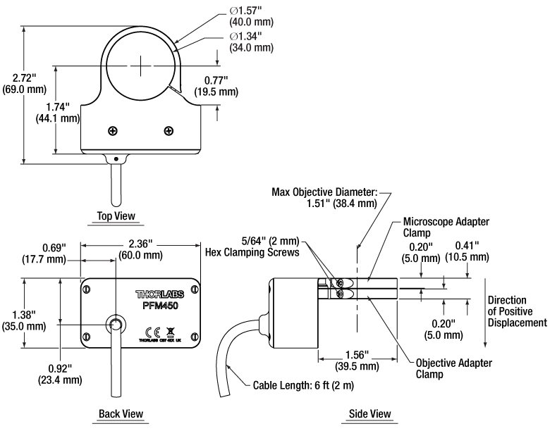
| Dimensions | 2.72" x 2.36" x 1.38" (69.0 mm x 60.0 mm x 35.0 mm) |
| Weight | 380 g (0.84 lbs) |
| Operating Temperature Range | 5 to 40 °C |
| Controller Specificationsa | ||
|---|---|---|
| Piezoelectric Output | ||
| Drive Voltage Range | -30 V to +150 V | |
| Drive Voltage Stability | 100 ppm over 24 Hours (After 30-Minute Warm-Up) |
|
| Drive Voltage Noise | <0.5 mV (RMS)b | |
| Output Current | 150 mA | |
| External Input BNC | ||
| Input Voltage Rangec | -10 V to +10 V | |
| Open Loop | 1 V Input = 15 V Drive Voltage | |
| Closed Loop | 1 V Input = 45 µm Displacement | |
| Input Impedance | 10 kΩ | |
| Absolute Maximum Input Voltage | ±20 VDC | |
| External Output BNC | ||
| Output Voltage Range | 0 V to +10 V Outputs Unprocessed Feedback, Linearized Feedback, or Signal Proportional to Drive Voltage; Selectable in the Software |
|
| Output Impedance | 100 Ω | |
| Minimum Recommended Output Impedance | 10 kΩ | |
| Physical Specifications | ||
| Input Powerd | Input Voltage | 24 VDC ± 5% |
| Input Current | <2 A | |
| Dimensions | 205.0 mm x 147.0 mm x 68.3 mm (8.07" x 5.79" x 2.69") |
|
| Weight | 1.65 kg (3.63 lbs) | |
| Operating Temperature Range | 5 to 40 °C | |
Click to Enlarge
Mechanical Drawing of Scanner
Click to Enlarge
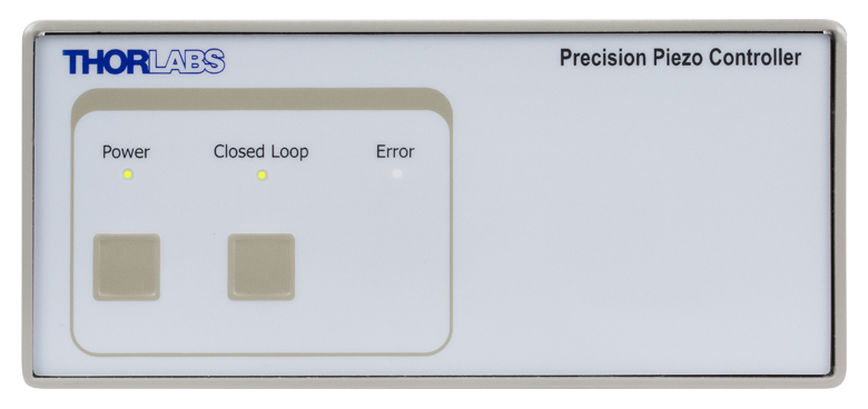
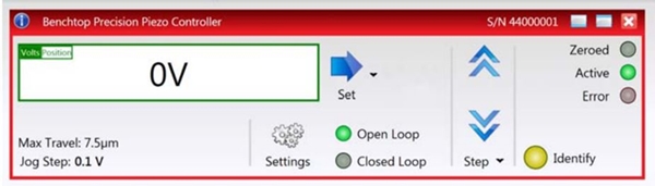
Front Panel of PPC001 Piezo Controller
In the software, the front panel LEDs can be set to three intensities: full, dim, or off. The dim mode, shown above, is the default setting.
Click to Enlarge
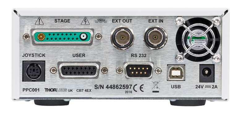
Back Panel of PPC001 Piezo Controller
Information on the connectors is available in the Pin Diagrams tab.
Software and External Control
Software
Kinesis Version 1.14.52
The Kinesis Software Package includes a GUI for control of the Piezo Objective Scanner.
Also Available:
- Communications Protocol
![]()
Click to Enlarge
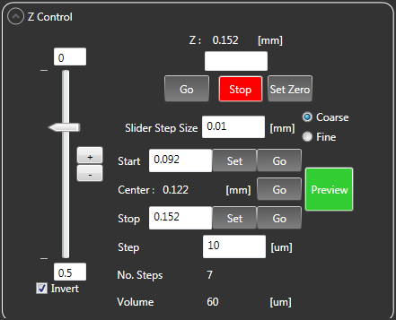
Z Control Panel from ThorImage®LS Capture Setup Tab
Click to Enlarge
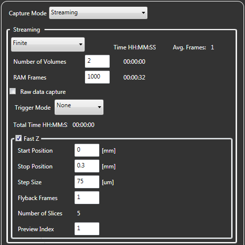
Fast Z Panel from ThorImageLS Capture Tab
The scanner can be driven using the included standalone Kinesis® GUI, our ThorImage®LS software for Bergamo® III and confocal microscopes, or an externally supplied control voltage. In addition, a DB15 connector provides signals that can be used for synchronization with external equipment. Complete details on control are available in the PFM450E Kinesis manual (PDF link).
Open-Loop Operation vs. Closed-Loop Operation
There are two operating modes for positioning the objective: open loop and closed loop. In open-loop operation, which supports a travel range of
600 µm ± 10%, the user controls the piezo drive voltage (in V). The applied drive voltage corresponds to some amount of objective displacement. For piezoelectric materials, this displacement does not depend linearly on the applied voltage: it exhibits nonlinearity and hysteresis. It is therefore not straightforward to position the objective by choosing the drive voltage. The scanner's built-in capacitive feedback sensors measure the objective displacement with 1 nm resolution in open-loop operation.
In closed-loop operation, which supports a travel range of 450 µm, the user directly controls the objective displacement (in µm). The built-in capacitive feedback sensors measure the objective displacement with 3 nm resolution in closed-loop operation.
Click to Enlarge
Kinesis® GUI Panel
Standalone Kinesis GUI
The Kinesis GUI supports both open- and closed-loop operation. The piezo drive voltage or objective displacement can be directly typed in or incremented or decremented in fixed, user-defined amounts.
In addition, the GUI enables software-based PID loop tuning. The default settings are designed to provide stable operation for most small- and medium-sized objectives, but fine tuning the PID loop helps account for the specific microscope and objective in use in the experiment, reducing positional overshoots and ringing about the commanded objective position.
A screenshot is shown to the left.
ThorImageLS Image Acquisition Software
ThorImageLS supports closed-loop operation. It allows the movement of the objective scanner to be controlled from the same interface as Thorlabs' Bergamo III and confocal microscopes, greatly simplifying experimental integration. For convenience, controls for the piezo objective scanner are found in both the Capture Setup and Capture tabs. Screenshots are shown to the right.
Externally Supplied Control Voltage
In this mode, the scanner supports both open- and closed-loop operation. The voltage is applied using the external input BNC connector on the controller. In open-loop operation, a 1 V change in input voltage results in a 15 V change in drive voltage, while in closed-loop operation, a 1 V change in input voltage results in a
45 µm change in objective displacement. The drive voltage or objective displacement that is determined by the input voltage is added to the value that is set in the GUI. If this sum would result in a drive voltage outside the -30 V to +150 V range, those limits will not be exceeded.
The external input BNC connector is typically used with sine, sawtooth, or square drive signals. The maximum frequency of the signal that should be applied depends upon the waveform. For large periodic waveforms (i.e., sine waves that provide >200 µm of total displacement), the recommended drive frequencies are:
- ≤25 Hz for Loads up to 150 g,
- ≤20 Hz for Loads from 150 g to 250 g,
- ≤15 Hz for Loads from 250 g to 400 g, and
- ≤10 Hz for Loads from 400 g to 500 g.
For staircase waveforms with step sizes up to 50 µm, the minimum time between steps can be as small as the 25 ms typical settling time.
DB15 Connector
For photostimulation, electrophysiology, and optogenetics applications, the DB15 connector on the controller provides several electrical signals that can be used to synchronize the movement of the piezo objective scanner with other equipment, such as multiphoton imaging lasers, patch clamp electrodes, and LED light sources. Details on this connector are available in Appendix A.2 of the manual (PDF link).
External Control Voltage Examples
Click to Enlarge
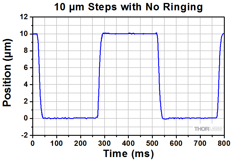
We applied a square wave drive signal to our piezo controller to move a 16X physiology objective (Item # N16XLWD-PF) in 10 µm increments. The scanner's built-in capacitive sensors demonstrate that the targeted position is achieved within the 25 ms typical settling time without ringing.

Click to Enlarge
We used a sawtooth drive signal to acquire a Z-stack with a 16X physiology objective (Item # N16XLWD-PF). As shown by the built-in capacitive sensors, we obtained excellent linearity over the 300 µm scan range, creating evenly spaced image slices.
Piezo Controller Pin Diagrams
Stage Connector
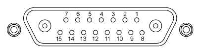
| Pin | Description | Pin | Description |
|---|---|---|---|
| 1 | HV Ground (Return) | 8 | HV Ground (Return) |
| 2 | Not Used | 9 | Not Used |
| 3 | Not Used | 10 | Stage IDb |
| 4 | Sine Wave Drive Output | 11 | Low Voltage Ground |
| 5 | Not Used | 12 | Low Voltage Ground |
| 6 | +15 V (Preamp Supply)a | 13 | Piezo ID (Legacy Stages)b |
| 7 | Low Voltage Ground | 14 | Position Sense Input (Strain Gauge) |
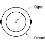
| Coaxial Male |
Position Sense Input (Capacitive) |
15 | -15 V (Preamp Supply)a |
| Coaxial Female |
HV Output |
User Connectora
Female DB15
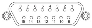
| Pin | Description | Return | Pin | Description | Return |
|---|---|---|---|---|---|
| 1 | Digital Output 1 | 5, 9, 10 | 9 | Digital Ground | - |
| 2 | Digital Output 2 | 5, 9, 10 | 10 | Digital Ground | - |
| 3 | Digital Output 3 | 5, 9, 10 | 11 | For Future Use (Trigger Out) |
5, 9, 10 |
| 4 | Digital Output 4 | 5, 9, 10 | 12 | For Future Use (Trigger In)b |
5, 9, 10 |
| 5 | Digital Ground | - | 13 | Digital Input 4 | 5, 9, 10 |
| 6 | Digital Input 1 | 5, 9, 10 | 14 | 5 V Supply Output | 5, 9, 10 |
| 7 | Digital Input 2 | 5, 9, 10 | 15 | 5 V Supply Output | 5, 9, 10 |
| 8 | Digital Input 3 | 5, 9, 10 |
Computer Control via RS-232
Male DB9
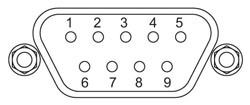
| Pin | Description | Pin | Description |
|---|---|---|---|
| 1 | Not Connected | 6 | Not Connected |
| 2 | RX (Controller Input) | 7 | Not Connected |
| 3 | TX (Controller Output) | 8 | Not Connected |
| 4 | Not Connected | 9 | Not Connected |
| 5 | Ground |
Computer Control via USB
Female Type B USB

External Input
BNC Female
Input Voltage: -10 V to +10 V
Input Impedance: 10 kΩ
External Output
BNC Female
Output Voltage: 0 V to +10 V
Output Impedance: 100 Ω
Minimum Recommended
Output Impedance: 10 kΩ
Joystick Connector
Female Mini DIN
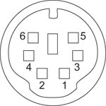
| Pin | Description | Pin | Description |
|---|---|---|---|
| 1 | RX (Controller Input) | 4 | +5 V, 100 mA Supply for Joystick |
| 2 | Ground | 5 | TX (Controller Output) |
| 3 | Ground | 6 | Ground |
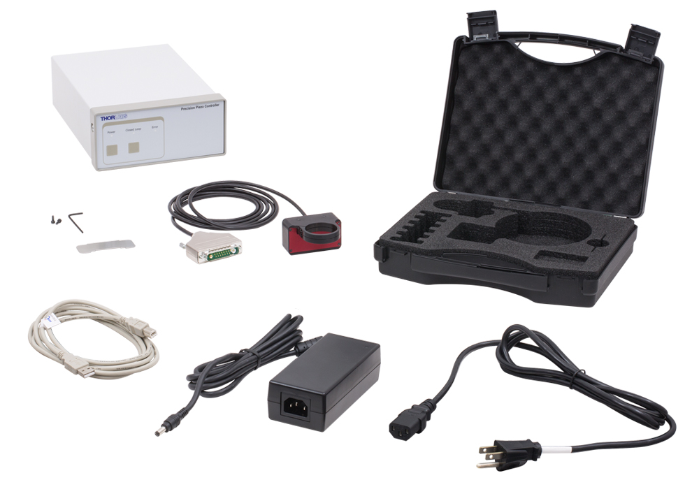
Click to Enlarge
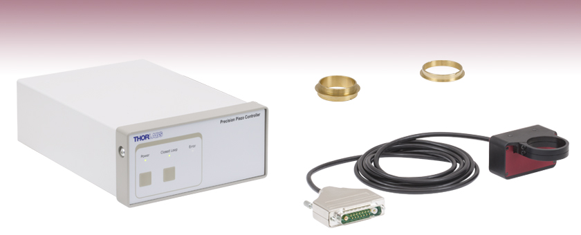
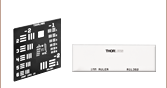
Items Included with PFM450E (North American Power Cord Shown)
Item # PFM450E consists of the following:
- PFM450 Piezo Objective Scanner
- PPC001 Piezo Controller
- Spanner Wrench for Adapter Installation
- 5/64" (2 mm) Hex Key and Two Extra Cap Screws for Piezo Objective Scanner's Flexure Clamps
- Power Supply with Region-Specific Power Cord
- USB Cable for Computer Connections
- Storage Case with Slots for Piezo Objective Scanner, Spanner Wrench, and Brass Adapters
The brass adapters required to connect the piezo objective scanner to the microscope and the objective are sold separately.
| Posted Comments: | |
do'neill
(posted 2024-08-28 11:49:09.0) Thank you for you feedback. The PPC001, as part of the PM450E, is currently not supported in micromanager. However this is an active project and support for this is in progress. I will reach out ot you directly to further discuss this and your application. Craig Wall
(posted 2024-08-07 08:38:46.753) Hi, I would like to extend the cable connecting the PFM450E scanner and controller by 3m so that the total length is 5m. If 5m is too long, we could also extend by 1m, so the total length is 3m. Can you please recommend an extension cable for this? rcapehorn
(posted 2024-08-07 05:12:33.0) Thank you for your enquiry. We'd be happy to support your request. I will reach out directly to discuss your requirements further. spolineni
(posted 2024-08-13 09:33:33.0) Thank you for your inquiry. The PFM450 Piezo Objective Scanner and PPC001 Piezo Controller, sold together as Item PFM450E, are factory-calibrated as a matched pair with identical serial numbers. I will contact you shortly to discuss your application further and provide any necessary assistance. Clemens Alt
(posted 2024-01-08 10:47:21.993) Good morning,
I am looking for a microscope objective positioner. But for our application, the axis of light propagation is horizontal, i.e., the objective is mounted horizontally and needs to move horizontally to shift the focus. Our objective weighs almost 300 g and is 90 mm long, so the center of gravity would be 10s of mm away from the mounting ring.
Can the PFM450E support such a load?
Thank you. cstroud
(posted 2024-01-10 11:16:15.0) Thank you for your enquiry. The maximum load for this stage is 500g in any orientation, and we recommend that the centre of mass is as close as possible to the stage. I will reach out to you directly to discuss your particular application. Charlie O'Mahony
(posted 2023-08-21 12:49:13.287) Hi there, I've been using the PFM450 for a couple of year now, but today it started making a crunching noise, followed by an error showing up on the controller, without any movement. The controller is probably fine, but I fear the piezo objective controller has burnt out. Firstly is there any recommendations for remedying it, but more than likely what I'm asking is it possible to price just the objective controller alone, not the piezo controller box?
Best regards,
Charlie do'neill
(posted 2023-08-22 04:46:25.0) Response from Daniel at Thorlabs. I will reach out to you directly to discuss the best options to remedy this for you as the stages are paired with their controllers. user
(posted 2023-08-08 13:11:49.07) Hi,
Can you add mounting holes for e.g. 8-32 or 1/4-20 screws to this? We do not have a microscope to which we are mounting this holder and it is not convenient to mount it as shown in your example using the circular adapter. fguzman
(posted 2023-08-14 07:51:04.0) Thanks for your enquiry. The PFM450E Piezo Objective Positioner is designed and engineered for compatibility with Thorlabs' Bergamo® II Multiphoton Microscopes, our Confocal Imaging System, our Cerna® Microscopy Platform, and third-party microscope. You could use the microscope adapters and use some other optomechanical components to use it for your application. Lee In jae
(posted 2022-01-21 00:26:12.9) Dear engineers of Thorlabs,
Hi, our labratory recently bought your product PFM450E, Piezo Objective Scanner and paired Controller.
We have two inquiries about your products.
At first, Is there any way we can see measured distance in three-digits nanometer level in closed loop mode? We are using external signal for input voltage of controller in closed loop mode. We want to see corresponding position data in more precise level such as 32.358 micrometer not 32.36 micrometer.
Secondly, can we take position data through your software(APT), or in any other ways? We are using external stepped voltage signal as a controller input. So we want to acquire position data corresponding to each step.
Thank you. DJayasuriya
(posted 2022-01-24 04:29:07.0) Thank you for your inquiry. We will get in touch with you directly to resolve your issue. DJayasuriya
(posted 2021-09-27 05:39:50.0) Thank you for your inquiry. We will get in touch with you directly. fredrik pettersson
(posted 2021-06-01 05:12:21.463) Hello,
I'm trying to figure out what this system uses as a feedback signal for detecting the substrate. Does it use a camera image? How can I set this up in a system where I replace the camera signal during measurements with an emission signal, that does not correspond the topography of the sample?
Cheers, Fredrik cwright
(posted 2021-06-02 08:32:14.0) Response from Charles at Thorlabs: Thank you for your query. The PFM450E does not have an inbuilt way of detecting a substrate but the controller used in the PFM450E has the option of being controlled by an external source supplying a voltage of -10V to +10V, which is summed with the software demanded position. If using the external input alone then 0V to +10V would correspond to the full travel range of the device. This allows the PFM450E to be controlled by another device which could detect the substrate. Soham Pal
(posted 2021-03-24 20:00:31.393) Hello,
I am a postdoc at Cavendish Laboratory, University of Cambridge and we are setting up a new confocal setup. Please provide a formal quote for PFM450E - Piezo Objective Scanner and Paired Controller, along with a M25 adapter for the microscope objective, as soon as possible. YLohia
(posted 2021-03-25 10:51:46.0) Hello, formal quotes can be requested by contacting your local Thorlabs Sales Team (sales.uk@thorlabs.com in your case) or by adding the item to your cart and selecting "Request a Quote" in the cart view. We will reach out to you directly. craig.brideau
(posted 2017-09-22 14:31:54.19) It would be nice to have a way to store the PID constants for different objectives into the system. Having to re-enter them from a notebook every time the objective is changed works but some sort of memory or storage (even in the app) would be nice. tfrisch
(posted 2017-09-26 05:37:48.0) Hello, thank you for contacting Thorlabs. PID settings can be stored in Kinesis. We will reach out to you about this functionality. kwestla
(posted 2016-07-26 14:43:12.873) Any plans on making M26 adapters for mitutoyo/motic systems? bhallewell
(posted 2016-07-29 11:22:16.0) Response from Ben at Thorlabs: Thank you for your question here. This is an option that we are looking into bringing into our range of objective adapters in the coming weeks. |

 Zoom
Zoom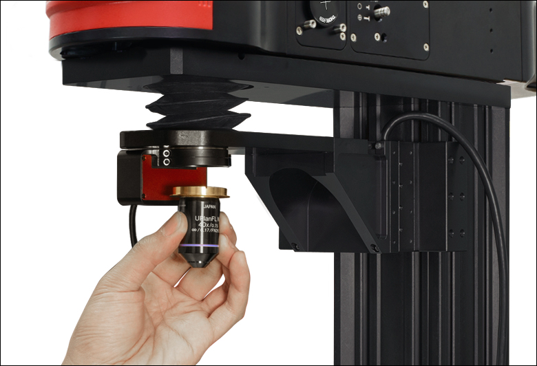
Click to Enlarge
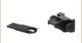
Since the flexure clamps are independent, the objective can be exchanged without detaching the scanner.
Click to Enlarge
The microscope and objective adapters are installed in the scanner using two independent flexure clamps. The clamps are tightened using the 5/64" (2 mm) hex key included with the unit.
- Includes All Items Shown in PFM450E Shipping List Tab
- Requires Microscope and Objective Adapters Sold Below
The PFM450 Piezo Objective Scanner and PPC001 Piezo Controller are sold as Item # PFM450E in a matched, factory-calibrated pair. Each is labeled with an identical serial number. It is not recommended to operate the piezo objective scanner with a different controller.
For large periodic waveforms (i.e., sine waves that provide >200 µm of total displacement), the recommended drive frequencies are:
- ≤25 Hz for Loads Up to 150 g,
- ≤20 Hz for Loads from 150 g to 250 g,
- ≤15 Hz for Loads from 250 g to 400 g, and
- ≤10 Hz for Loads from 400 g to 500 g.
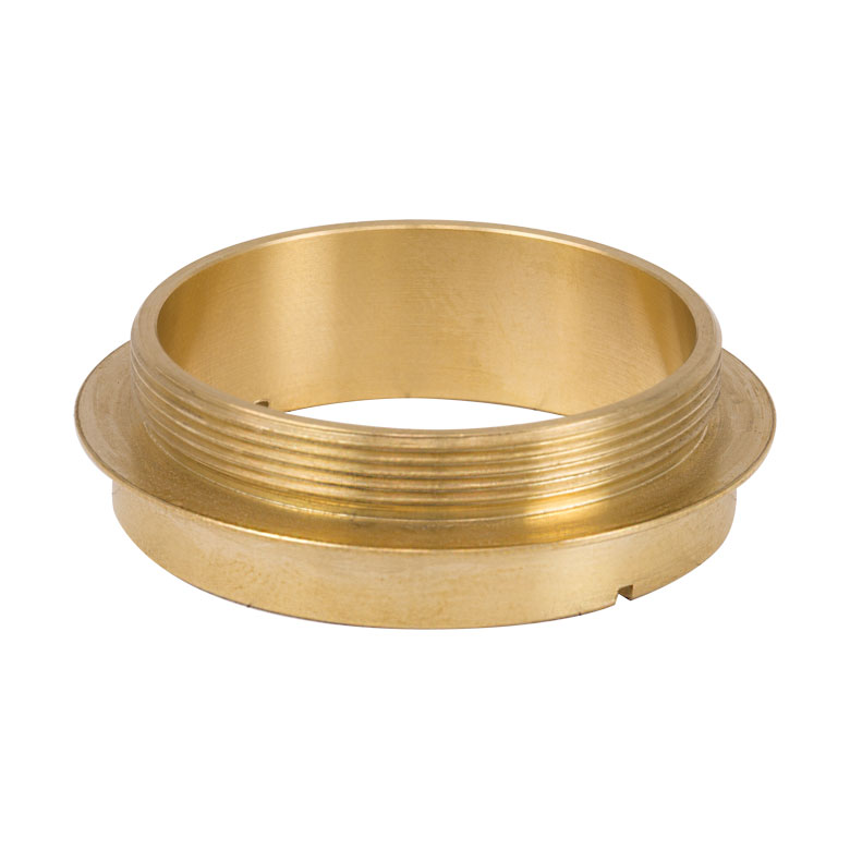
These externally threaded brass adapters connect the scanner to the microscope's objective holder. The bottom contains two spanner wrench slots for installing the adapter. A compatible spanner wrench is included with the PFM450E.
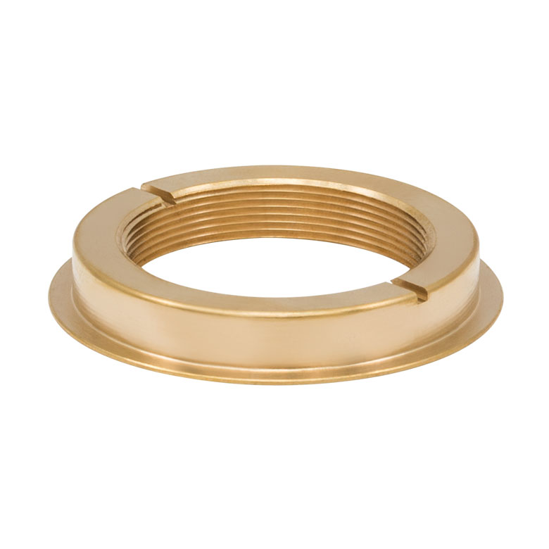
The PFMA01E Extended Microscope Adapter with M32 x 0.75 objective threads offers a thicker flange than the PFMA01 Microscope Adapter, which is useful for microscopes with recessed objective threads, such as our Bergamo III multiphoton microscopes. The PFMA01E's inner surface is also roughened to improve signal collection for multiphoton microscopy.
Click to Enlarge
PFMA01E
Extended M32 x 0.75 Microscope Adapter
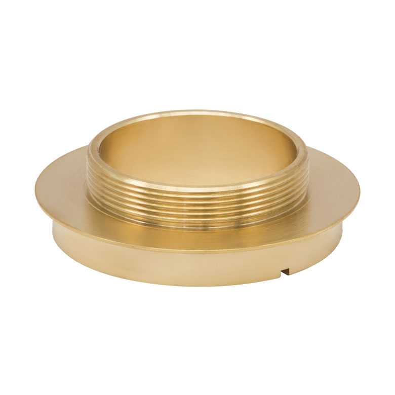

These internally threaded brass adapters connect the scanner to the objective. The top contains two spanner wrench slots for installing the adapter. A compatible spanner wrench is included with the PFM450E.