 Products Home / Imaging Components / Detectors for Microscopy / Microscope Slide Power Meter Sensor Heads
Microscope Slide Power Meter Sensor Heads
- Measure Power at the Sample
- Large-Area Sensor to Collect Light from High NA Objectives (up to 1.45)
- Compatible with Dry, Water Immersion, and Oil Immersion Objectives
- Options Available for Low-Power, High-Power, and Multiphoton Applications
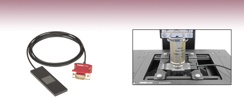
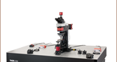
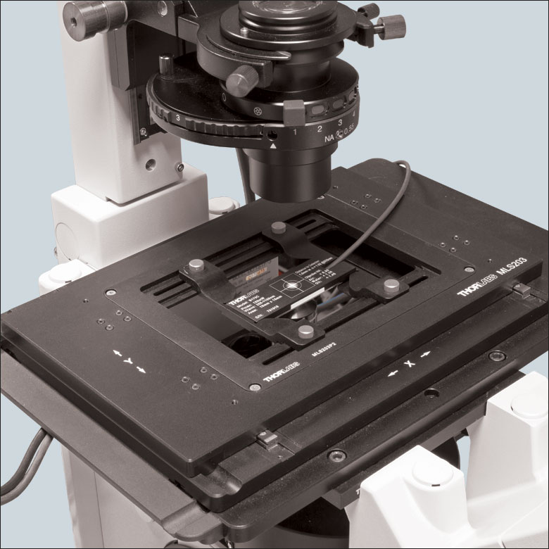
S170C Microscope Slide Power Meter Sensor used with a 1.30 NA Objective and Shown on an MLS203-1 Motorized Scanning Stage Equipped with an MLS203P2 Slide Holder
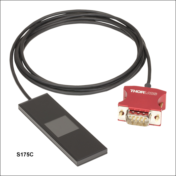
S175C
High-Power Microscope Slide Power Sensor for UV, Visible, and IR


Please Wait
Click to Enlarge
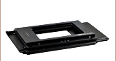
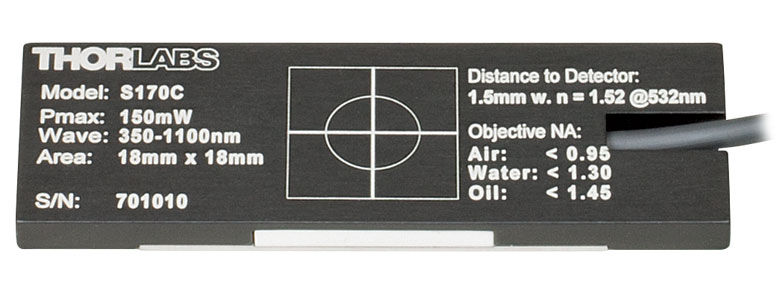
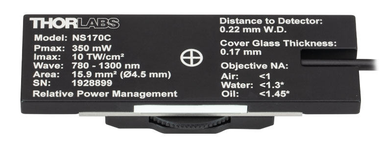
The back of each microscope slide sensor housing is engraved with the sensor specifications and a crosshair for centering the beam on the sensor. This image shows the engravings on the S170C sensor; the S171C sensor has similar engravings. The engravings on the S175C and NS170C sensors are shown further below.
 Click for Details
Using the engraved alignment target on the back of the sensor housing, a user can position the stage so that when the sensor is flipped, the beam strikes the center of the sensor. The S170C sensor is shown in this image.
Features
- Compatible with Standard Upright and Inverted Microscopes
- Designed to Measure Power at the Sample Plane
- Large 18 mm x 18 mm Active Sensor Area
- Low-Power Photodiode Sensors:
- Wavelength Range: 350 nm to 1100 nm (Item # S170C) or 400 nm to 1100 nm (Item # S171C)
- Sensitive to Optical Powers from 10 nW to 150 mW (Item # S170C) or 1 nW to 15 mW (Item # S171C)
- High-Power Thermal Sensor (Item # S175C)
- Wavelength Range: 300 nm to 10.6 µm
- Measure Optical Powers from 100 µW to 2 W
- Second-Order Nonlinear Crystal with Photodiode Sensor for Multphoton Microscopy (Item # NS170C)
- Laser Wavelength Range: 780 - 1300 nm
- Sensitive to Average Optical Powers from 0.5 - 350 mW with Max Peak Power Density of 10 TW/cm2
- Sensor Housing with the Same Footprint as Standard Microscope Slides: 76.0 mm x 25.2 mm
- Novel Optical Designs Accommodates High NA Objectives (see Optical Design tab)
- Information Stored in Connector:
- Sensor Data for Automatic Calibration when Using Thorlabs' Power Meter Consoles
(Sold Separately Below) - NIST- and PTB-Traceable Calibration Data
- Sensor Data for Automatic Calibration when Using Thorlabs' Power Meter Consoles
- Recalibration Service Available
Applications
- Measure Intensity of the Microscope Light Source at the Sample Plane
- Determine Transmission of a Fluorescence Filter Set
- Ensure Lighting Conditions are Consistent Between Experiments
- Optimize Pulse Duration at the Focus of a Multiphoton Microscope using a Femtosecond Pulse Compressor
Thorlabs' Microscope Slide Power Sensor Heads are designed to measure optical power at the sample in microscopy setups. These sensor heads have the same footprint (76.0 mm x 25.2 mm) as a standard microscope slide, feature a large 18 mm x 18 mm active area, and are compatible with most standard upright and inverted microscopes.
The low-power versions incorporate silicon photodiode sensors, while the high-power version is equipped with a thermal sensor. The S170C photodiode sensor is sensitive to wavelengths from 350 nm to 1100 nm at optical powers from 10 nW to 150 mW with 1 nW resolution. The S171C photodiode sensor is for wavelengths from 400 nm to 1100 nm at optical powers from 1 nW to 15 mW with a resolution of 0.5 pW. A <1 µs response time makes these sensors ideal for high-resolution measurements using lasers, but they are still well suited for measurements of broadband illumination sources, like LEDs and white light sources. The S175C thermal sensor is sensitive to wavelengths from 300 nm to 10.6 µm at optical powers from 100 µW to 2 W. This sensor features a flat absorptivity over the specified wavelength range, making it ideal for measurements of broadband illumination sources, like LEDs and white light sources.
The NS170C microscope slide sensor is designed to measure the relative peak power of two-photon lasers. The sensor utilizes a nonlinear β-BBO (beta-BaB2O4) crystal to convert femtosecond near-infrared (NIR) pulses into their second harmonic, and a silicon photodiode detector to measure the visible second harmonic signal. It can be used with femtosecond lasers with center wavelengths from 780 nm to 1300 nm and average powers from 0.5 mW to 350 mW. The maximum peak power density should not exceed 10 TW/cm2 at 80 MHz repetition rate and for microscope objectives with NA > 0.5; the damage threshold will be lower for NA < 0.5. This design enables the sensor to measure the relative peak power at the focus of the microscope, making it ideal for laser pulse optimization for multiphoton imaging. Please see the Specs tab for more information.
Click to Enlarge
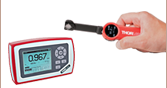
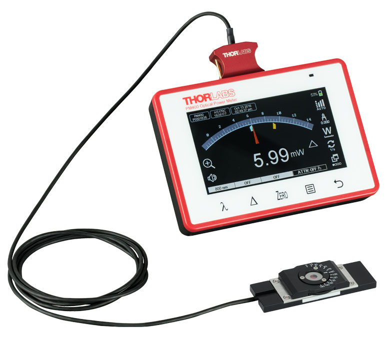
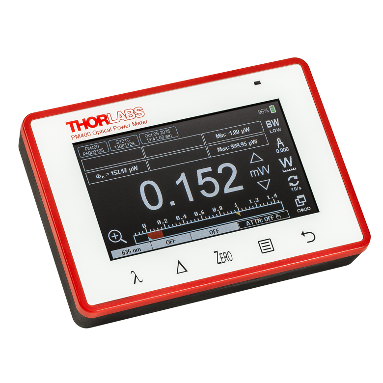
The NS170C sensor connected to the PM400 touch screen power meter console (sold separately).
Day-to-Day Usage
The sensors support power measurements for objectives with NAs up to 1.45, and are usable in air and with water- or oil-based immersion media (see the Optical Design tab for details). As seen in the image above to the right, the back of the sensor is engraved with the recommended NA for air (<0.95 for the S170C, S171C, and S175C sensors, and <1 for the NS170C sensor), water (<1.30), and oil (<1.45) objectives. The active sensor area is protected by a glass cover surface, which can be easily cleaned using compressed air or using optic tissue moistened with acetone or methanol.
As seen in the image above, the bottom of these sensors feature a laser-engraved alignment crosshair that marks the active sensor area to aid in aligning and focusing the beam. To use with a standard upright microscope, insert the housing into the beam path so that the engraved side is facing the objective of your microscope. Once the power sensor is centered under the objective, turn the slide over so that the detector is facing the beam in order to take a power measurement. For inverted microscopes, place the detector in your slide holder with the sensor facing the objective and turn on the trans-illumination lamp. Centering the beam on the engraved target will center the sensor in the optical path.
To avoid damaging the sensor, we recommend positioning it in the light path at a location where the beam is not focused. It is important not to exceed the Max Average Power Density for the S170C, S171C, and S175C sensors, or the Max Peak Power Density for the NS170C sensor (see Specs tab) over the beam's spot size.
Power Meter Console and Interface Compatibility
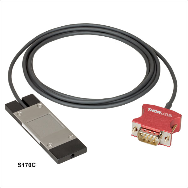
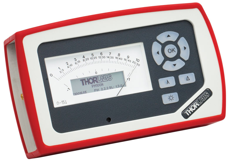
These power sensor heads are compatible with the PM100D, PM100A, PM400, and PM5020 power meter consoles, as well as many of our C-series power and energy meter interfaces, which provide communication between the sensor and an external control unit such as a PC. The PM100A, PM100D, and PM400 consoles, which include display screens and controls, are sold below for convenience. As seen in the image to the left, a 1.5 m cable attached to the side of the sensor head leads to a D-sub 9-pin male connector. Sensor specifications for automated calibration and the NIST- and PTB-traceable calibration data are stored in non-volatile memory in the sensor connector and can be read out using compatible Thorlabs power meter consoles.
Recalibration Service
Recalibration services are available for our power sensors and power meter consoles. We recommend your Thorlabs sensor and console be recalibrated as a pair; however, each may be recalibrated individually. Recalibration of a single-channel power and/or energy meter console or interface is included with the CAL-PD Si Photodiode, CAL-THPY Termal Sensor, and CAL-NS Nonlinear Crystal with Si Photodiode Recalibration Services below at no additional cost. We recommend yearly recalibration to ensure accuracy and performance. Please contact Tech Support for assistance..
| Specifications | |||||
|---|---|---|---|---|---|
| Item # | S170C | S171C | S175C | NS170C | |
| Detector Type | Silicon Photodiode | Thermal Absorber | Second-Order Nonlinear Crystal with Silicon Photodiode |
||
| Wavelength Range | 350 - 1100 nm | 400 - 1100 nm | 300 nm - 10.6 µm | Laser: 780 - 1300 nm SHG: 390 - 650 nm |
|
| Optical Power Working Range | 10 nW - 150 mW | 1 nW - 15 mW | 100 µW - 2 W | Laser: 0.5 - 350 mWa SHG: 10 nW - 5 mW |
|
| Max Average Power Density | 20 W/cm2 | 10 W/cm2 | 200 W/cm2 | - | |
| Max Pulse Energy Density | - | - | 0.1 J/cm² (1 µs Pulse) 1 J/cm² (1 ms Pulse) |
- | |
| Max Peak Power Densityb | - | - | - | 10 TW/cm2 | |
| Linearity | ±0.5% | ±0.5%c | |||
| Resolution | 1 nWd | 0.5 pWe | 10 µWf | 1 nWc,d | |
| Measurement Uncertainty | ±3% (440 - 980 nm)g ±5% (350 - 439 nm)g ±7% (981 - 1100 nm)g |
±3% (440 - 980 nm)g,h ±5% (400 - 439 nm)g,h ±7% (981 - 1100 nm)g,h |
±3% (1064 nm) ±5% (300 nm - 10.6 µm) |
±3% (440 - 650 nm)c,i ±5% (390 - 439 nm)c,i |
|
| Responsivity (Click for Plot) |
 Raw Data |
 Raw Data |
- |  Raw Data |
|
| Absorption (Click for Plot) |
- | - |  Raw Data |
- | |
| Typical Application | Light Measurement on the Microscope Objective Plane | GDD Optimization of a Femtosecond Laser at the Focus of a Two-Photon Microscopej | |||
| Neutral Density Filter | Reflective (OD 1.5) | Absorptive (OD 0.4) | N/A | N/A | |
| Cooling | Convection | ||||
| Compatible Consolesk | PM100D, PM100A, PM400, and PM5020 | ||||
| Compatible Interfacesk | PM101, PM101A, PM101R, PM101U, PM103, PM103A, PM103E, PM103U, and PM100USB | PM101, PM101A, PM101R, PM101U, PM102, PM102A, PM102U, and PM100USB | PM101, PM101A, PM101R, PM101U, PM103, PM103A, PM103E, PM103U, and PM100USB | ||
| Response Time | <1 µs | <2 s | <1 µs | ||
| Dimensions | 76.0 mm x 25.2 mm x 5.0 mm (2.99" x 0.99" x 0.20") |
76.0 mm x 25.2 mm x 4.8 mm (2.99" x 0.99" x 0.19") |
Base: 76.0 mm x 25.2 mm x 5.0 mm (2.99" x 0.99" x 0.20") Overall: 76.0 mm x 30.0 mm x 11.0 mm (2.99" x 1.18" x 0.43") |
||
| Active Detector Area | 18 mm x 18 mm | ||||
| Input Aperture | 20 mm x 20 mm | 18 mm x 18 mm | Ø4.5 mm | ||
| Working Distance | - | - | - | 0.22 mm | |
| Cable Length | 1.5 m | ||||
| Connector | Sub-D 9 Pin Male | ||||
| Weight | 0.07 kg (0.15 lbs) | 0.05 kg (0.11 lbs) | 0.08 kg (0.18 lbs) | ||
| Post Mounting | Combi Thread 8-32 and M4 x 0.7 | N/A | Combi Thread 8-32 and M4 x 0.7 | ||
Sensor Connector
D-type Male
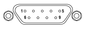
| Pin Connections | ||
|---|---|---|
| Pin | S170C, S171C, and NS170C | S175C |
| 1 | Not Used | |
| 2 | EEPROM Data | |
| 3 | Photodiode Anode Ground | Sensor Ground |
| 4 | Photodiode Cathode | Not Used |
| 5 | Not Used | |
| 6 | EEPROM Ground | |
| 7 | Not Used | Not Used |
| 8 | Not Used | Sensor Signal |
| 9 | Not Used | |
Cleaning
The housing of these microsope slide power meter sensor heads can be cleaned using a soft damp cloth. To clean the ND filter of the S170C and S171C sensors, gently blow off any debris using compressed air. The surface may be gently wiped using an optic tissue moistened with acetone or methanol. The glass sensor cover of the S175C and NS170C sensors can be cleaned with appropriate solvents like isopropanol.
Calibration
The calibration of the sensors in these sensors should remain stable for over a year provided that the unit has not been exposed to excessive optical powers. We recommend yearly recalibration to ensure accuracy and performance, which may be ordered using the CAL-PD for Item #s S170C and S171C, CAL-THPY for Item # S175C, or CAL-NS for Item # NS170C. Please contact Tech Support for assistance.
The sections below describe the various designs of Microscope Slide Power Meter Sensor Heads. Use the following links to jump to a specific section:
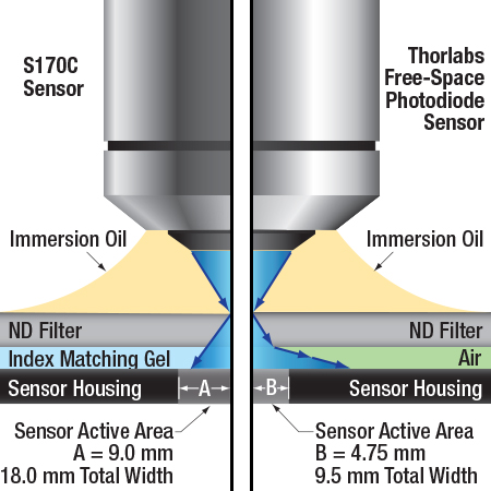
An illustration to show the behavior of light exiting a high NA objective after it enters the S170C microscope power sensor head vs. a typical photodiode sensor. For objectives with NAs greater than 1.0 and a detector without index matching gel in the gap, some of the light will also undergo total internal reflection at the ND filter-air interface, causing additional losses before the light reaches the sensor. (Important Note: Do not place immersion oil or other immersion media directly on the ND filter of any Thorlabs photodiode detectors other than the S170C and S171C sensors, as they were not designed for this application and the oil cannot be cleaned from the filter surface.)
Large Active Area and Index Matching Gel
The S170C, S171C, and S175C microscope slide sensor heads were designed with large-active-area detectors to accommodate high NA objectives. In addition, the S170C and S171C sensors use index matching gel in the gap between the neutral density filter and the sensor to minimize losses due to internal reflections at the air-glass interface. The S175C sensor uses a protective glass cover that features a smaller air gap than the S170C sensor (0.15 mm versus 1.5 mm) to avoid the use of index matching gel, which helps maintain a fast sensor response time.
The schematic to the right illustrates the advantages that a large-area detector like the one used in the S170C sensor provides over typical photodetectors by tracing the path of light from a high NA objective after it enters an S170C microscope slide sensor head and a typical photodiode sensor. The typical photodiode sensor shown in the drawing has an air-filled gap between the ND filtera and the sensor and a Ø9.5 mm active area, similar to our S130 slim photodiode sensors or S120 standard photodiode sensors. When light from a large NA objective reaches the interface between the ND filter and the glass, it refracts away from the center of the sensor. Some of the light misses the edge of the small active area of the photodiode, causing erroneous power measurements.
In the S170C microscope slide sensor head, the gap between the neutral density filter and the sensor active area has been filled with an index matching gel. Compared to the ND-filter-to-air interface in typical sensor heads, the gel minimizes the amount of reflected light at the ND-filter-to-gel interface that would otherwise not reach the sensor and eliminates refraction of light exiting the ND filter, allowing the large-area detector to capture more light from the objective. Please be aware that this design cannot completely compensate for this effect for very high NA oil objectives and at certain wavelengths.
Similar results would be expected from a comparison of the S175C unit with other thermal sensors. The small 0.15 mm air gap between the protective glass plate and the thermal sensor minimizes the light refracted away from the center of the sensor, while the large 18 mm x 18 mm active area catches more of the incoming signal. Additionally, the S175C sensor has a protective class cover plate that allows the appropriate immersion media for the objective to be applied without damaging the sensor. (Note: do not apply immersion media to Thorlabs' other thermal sensors, as it may damage to the sensor head.)
- Do not place immersion media directly on the ND filter of any Thorlabs' photodiode sensors, with the exception of the Microscope Slide Power Sensors that are specifically designed for this application, as the oil cannot be cleaned from the filter surface. The example used here is only intended to demonstrate the advantages of the S170C sensor's optical design.
 Click to Enlarge
An illustration to show the optical design of the NS170C Microscope Slide Peak Power Sensor. An ultrathin β-BBO crystal is used to convert femtosecond NIR laser pulses into their visible second harmonic. Shortpass filters reflect the residual NIR light, allowing only the visible second harmonic light to transmit to the silicon photodiode sensor.
Nonlinear Crystal with Silicon Photodiode Sensor
The NS170C Microscope Slide Peak Power Sensor was designed to measure the relative peak power of two-photon lasers. As shown in the diagram to the right, the sensor features a 30 µm ultrathin β-BBO crystal that converts incident femtosecond NIR pulses (780 – 1300 nm) into their second harmonic (390 – 650 nm). Shortpass filters underneath the β-BBO crystal reject the residual NIR light, allowing only the visible second harmonic light to transmit down to the large area silicon photodiode sensor.
A microscope objective is shown focusing the femtosecond NIR pulses into the β-BBO crystal through a Ø4.5 mm entrance aperture. Because the SHG process requires high peak intensities, the sensor only generates detectable second harmonic light when the ultrathin β-BBO crystal is in the focus of the objective. This means the NS170C sensor is sensitive to the peak power density of the focused femtosecond pulses rather than the average power; therefore, the detected SHG signal can be used as a relative measurement of the lasers' peak intensity. For more details on the generation of second harmonic light using β-BBO crystals, please see the SHG Tutorial tab.
At the top of the NS170C sensor is a standard 170 µm thick cover glass that is sealed to the housing, allowing it to be used with dry, water immersion, and oil immersion objectives. The immersion media can be placed directly on the surface of the cover glass without damaging the sensor. The working distance from the top of the cover glass to the β-BBO crystal is 0.22 mm. Between the cover glass and the β-BBO crystal is an 80 μm air-gap, which is necessary because epoxy or index-matching gel would burn in the focus of the high-intensity femtosecond pulses. While this air-gap causes total internal reflection (TIR) of the highest spatial frequencies when using high NA objectives, the second harmonic process in the β-BBO crystal has a finite spatial frequency acceptance bandwidth, which is exceeded by high NA objectives. Therefore, the highest spatial frequencies rejected by TIR would not appreciably contribute to the SHG process.
The housing of the NS170C sensor shares dimensions with a microscope slide and can fit on standard microscope stages, allowing for measurements of the relative peak power at the focus of a microscope.
For more information on the NS170C sensor, please see the full presentation for our microscope slide peak power sensor for two-photon lasers.
| Posted Comments: | |
Peter Gruber
(posted 2024-05-03 12:18:51.34) Newport is offering a photodiode microscope power sensor up to 600mW instead of the 150mW of the S170C.
https://www.newport.com/f/microscope-slide-photodiode-sensor
Sadly we had bad experience with the thermopile version and we would like to a photodiode alternative.
Is it possible to buy a calibrated version with 600mW of the S170C? dpossin
(posted 2024-05-06 09:18:13.0) Dear Peter,
Thank you for your feedback. At the moment I am not sure if we could extend the S170C to 600mW. I reach out to you in order to discuss your application in more detail. Vanessa Carlos
(posted 2023-04-28 15:02:03.27) Hello,
I would like to know if this power sensor can be completely immersed in water. Or if you have any other photodiode sensors where that is possible. I would need it for measuring power at the sample, on light sheet microscopes, using water immersion objectives, with low NA.
Thank you! dpossin
(posted 2023-05-02 04:33:31.0) Dear Vanessa,
Thank you for your feedback. The S170C is desgined for usage in immersion media. You can see the basic working principle here: https://www.thorlabs.de/newgrouppage9.cfm?objectgroup_id=2191&tabname=optical%20design. I am reaching out to you in order to discuss this further. Jolanda van Iperen
(posted 2023-01-09 16:35:59.607) I am looking for a mini laser intensity power meter that fits under the objectives of a u-Raman microscope (till 100x objective WD 0,17 and can focus with that working distance. It should be able to set laser at 532 nm and 785 nm in order to measure at these wavelength the power of the laser through the objectives, preferable reading the power outside the enclosure, which can be opened a little bit. I came to S170C, but cannot find if this is set to a particular wavelength or gives a spectrum. It would be nice to have both options - also for the LED light of the microscope- , but if not in the first place we prefer the first option to measure intensity of laser 532 and 785 nm. hkarpenko
(posted 2023-01-10 08:45:30.0) Dear Jolanda,
thank you for your feedback. Our sensors won´t be able to show the spectrum of the sensor, but only the power. S175C might be a more suitable sensor if you are measuring both, monochromatic and broadband lightsources. I contact you directly to discuss this in more detail with you. user
(posted 2021-11-09 06:01:57.003) What is the typical ambient-stabilization time between you take it in your hand, place it where you want to measure, and until you can actually measure? In our temp controlled lab, I've seen that this can go up to 10-15 minutes. Is that normal? dpossin
(posted 2021-11-16 06:02:54.0) Dear Carlos,
Thank you for your feedback. The stabilization time depends on the power level you would like to measure. In general thermal power sensors are very sensitive to external heat. Since convection is quite a slow process a settle time of 10 to 15 minutes is nothing to worry about. I am reaching out to you to discuss this further. Holger Knaut
(posted 2021-07-29 10:12:16.853) Hi,
is the S170C compatible with laser light illumination such as a confocal or spinning disk scope?
Thanks soswald
(posted 2021-08-02 03:11:26.0) Dear Holger,
thank you for your feedback.
The S170C can be used to measure laser light as long as the maximum power of 150 mW and the maximum power density of 20 W/cm² are not exceeded.
Please contact your local tech support team with more details on your light source, expected power and power density to discuss your application further. user
(posted 2019-07-03 16:32:40.697) We are looking for a power meter similar to this but maybe one that is a cylinder as we are wanting to characterize an assembly that is illuminated from six points located around the circumference.
Please contact me. MKiess
(posted 2019-07-05 10:20:23.0) This is a response from Michael at Thorlabs. Thank you for your inquiry. I have contacted you directly to discuss further details on custom possibilities and applications for this sensor. g.makey
(posted 2016-05-12 03:50:55.7) Hi,
Can S170C be used in reflective mode microscope while imaging? shallwig
(posted 2016-05-12 05:05:39.0) This is a response from Stefan at Thorlabs. Thank you for your inquiry. I have contacted you directly to discuss how the S170C can be used in your setup. donovan.harris.civ
(posted 2015-12-10 15:28:18.217) Couldn't find compatible meter for the S175C. Using Zeiss compatible collimated LED sources at full power. shallwig
(posted 2015-12-11 06:41:50.0) This is a response from Stefan at Thorlabs. Thank you very much for your inquiry. The S175C sensor is compatible with any of our currently available consoles PM100D, PM100A, PM100USB, PM200, PM320E. I will contact you directly to discuss your application in more detail. cuhrich
(posted 2014-01-21 16:09:02.123) I just noticed that my comment is the same as one posted here. We need this device built with a stronger ND filter as we will have powers closer to 1W down on the sample. Seems like a reasonable option to offer a high power version. tschalk
(posted 2014-01-23 04:56:30.0) This is a response from Thomas at Thorlabs. Thank you very much for your inquiry. At the moment we are not able to equip the sensor with a stronger ND-filter because these does not meet our specifications. 1W is far away from the current specification and we hope to increase the maximum power level up to 300mW in the future. I will contact you directly to discuss your application. flickingerd
(posted 2013-11-01 08:24:21.293) A model with Pmax 500 mW would be nice (powers like this are normal for narrow bandwidth 2P microscopy). tschalk
(posted 2013-11-06 03:19:31.0) This is a response from Thomas at Thorlabs. Thank you very much for your inquiry. At the moment we can not provide a sensor with a higher power range because of the optical filter that is used. I will contact you directly to discuss your application and find a suitable solution. cbrideau
(posted 2013-08-01 16:38:44.763) Looking good, but how do you deal with the NA narrowing imposed by the Si detector's high index of refraction (>3)? |

 Zoom
Zoom| Item #a | S170C | S171C |
|---|---|---|
| Wavelength Range | 350 - 1100 nm | 400 - 1100 nm |
| Optical Power Working Range | 10 nW - 150 mW | 1 nW - 15 mW |
| Max Average Power Density | 20 W/cm2 | 10 W/cm2 |
| Resolution | 1 nWb | 0.5 pWc |
Click to Enlarge
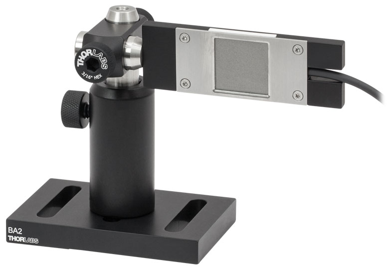
The S170C may be post mounted via the 8-32 (M4) tap in the side of the housing.
- Large 18 mm x 18 mm Sensor Active Area
- Ideal for Measuring Light from High NA Objectives or Any Position Along the Optical Path
- Yearly Recalibration with CAL-PD Recalibration Service Recommended
(For More Information, Contact Tech Support) - Post Mountable via 8-32 (M4) Tap
The S170C and S171C Microscope Slide Power Meter Photodiode Sensor Heads are designed to fit in the microscope slide holders of standard upright and inverted microscopes to measure the power at the sample plane. The active sensor is contained within a sealed housing, behind a neutral density (ND) filter with OD 1.5 (Item # S170C) or 0.4 (Item # S171C). A 20 mm x 20 mm indent above the ND filter accepts cover slips and immersion media. Immersion media (water, glycerol, oil, etc.) may be placed in this well directly over the ND filter, or a cover slip may be inserted first to simplify clean up. The S170C and S171C sensors use index matching gel in the gap between the neutral density filter and the sensor to minimize losses due to internal reflections at the air-glass interface. A detailed overview of these physical features is presented in the Optical Design tab.
With a fast response time of 1 µs, minimum power of 10 nW, and resolution of 1 nW, the S170C photodiode sensor is ideal for high-resolution power measurements of low-power illumination. Additionally, we offer the S171C sensor, which has a minimum power of 1 nW and a high resolution of 0.5 pW. The addition of water to a water dipping/ immersion objective always results in the absorption of some of the transmitted light, particularly in the near IR region. As such, power readings recorded without water will be higher than the values recorded with water.
The back of each slide is engraved with the sensor specifications and a grid for aligning the beam. To take a power measurement, simply flip over the slide to expose the sensor to the objective. In inverted microscopes, the trans-illumination lamp can be centered on the grid to ensure the sensor is centered on the beam.
Thorlabs recommends yearly recalibration of the S170C and S171C sensors. Thorlabs offers a recalibration service for these photodiode power sensors, which can be ordered below (see Item # CAL-PD). Recalibration of a single-channel power and/or energy meter console or interface is included with the recalibration of a sensor at no additional cost.

 Zoom
Zoom| Key Specificationsa | |
|---|---|
| Wavelength Range | 300 nm - 10.6 µm |
| Optical Power Working Range | 100 µW - 2 W |
| Max Average Power Density | 200 W/cm2 |
| Resolutionb | 10 µW |

Click to Enlarge
The back of the S175C housing is engraved with the sensor specifications and a target for centering the beam on the sensor.
- High-Power Thermal Sensor for 300 nm - 10.6 µm
- Designed to Measure Optical Powers from 100 µW to 2 W
- Large 18 mm x 18 mm Sensor Active Area
- Ideal for Measuring Light from High NA Objectives or Any Position Along the Optical Path
- Yearly Recalibration with CAL-THPY Recalibration Service Recommended (For More Information, Contact Tech Support)
The S175C Microscope Slide Power Meter Thermal Sensor Head is designed to fit in the microscope slide holders of standard upright and inverted microscopes to measure the power at the sample plane. The large-active-area 18 mm x 18 mm sensor is protected by a glass plate, allowing immersion media to be applied. With a <2 s response time , 100 µW to 2 W optical power range, and 10 µW resolution, this thermal sensor is suited for high-power measurements of broadband sources, such as LEDs or white light illumination. The addition of water to a water dipping/ immersion objective always results in the absorption of some of the transmitted light, particularly in the near IR region. As such, power readings recorded without water will be higher than the values recorded with water.
The back of the slide is engraved with the sensor specifications and a target for aligning the beam, shown in the photo to the right. To take a power measurement, simply flip over the slide to expose the sensor to the objective. In inverted microscopes, the trans-illumination lamp can be centered on the target to ensure the sensor is centered on the beam.
Please be aware that thermal sensors are sensitive to air vents and strong ambient temperature changes. Measurements should be taken once the sensor has settled to the ambient temperature.
Thorlabs recommends yearly recalibration of the S175C sensor. Thorlabs offers a recalibration service for this thermal sensor, which can be ordered below (see Item # CAL-THPY). Recalibration of a single-channel power and/or energy meter console or interface is included with the recalibration of a sensor at no additional cost.

 Zoom
Zoom| Key Specificationsa | |
|---|---|
| Laser Wavelength Range | 780 - 1300 nm |
| SHG Wavelength Range | 390 - 650 nm |
| Laser Optical Power Working Rangeb | 0.5 - 350 mW |
| SHG Optical Power Working Range | 10 nW - 5 mW |
| Max Peak Power Densityc | 10 TW/cm2 |
| Resolutiond | 1 nW |
 Click to Enlarge
The back of the NS170C housing is engraved with the sensor specifications and a target for centering the beam on the sensor.
- Utilizes a Second-Order Nonlinear Crystal to Measure the Relative Peak Power of Two-Photon Lasers
- Input Laser Wavelength Range: 780 - 1300 nm
- Second-Harmonic Wavelength Range: 390 - 650 nm
- Ideal for Optimizing Laser Conditions at the Sample Plane of a Microscope
- Compatible with Dry, Water Immersion, and Oil Immersion Objectives
- Yearly Recalibration with CAL-NS Recalibration Service Recommended (For More Information, Contact Tech Support)
- See the Full Web Presentation for More Information
The NS170C sensor is designed to measure the relative peak power of two-photon lasers by utilizing a second-order nonlinear β-BBO crystal to convert incident ultrafast NIR pulses into their visible second harmonic. Shortpass filters underneath the β-BBO crystal reject the residual NIR light, allowing only the second harmonic light to transmit down to a large area silicon photodiode sensor (see Optical Design tab for details). Because the efficiency of second harmonic generation (SHG) is proportional to the peak power density, or peak intensity, of the NIR femtosecond pulses, the magnitude of the detected second harmonic light provides a relative measurement of the peak power of the laser.
The NS170C sensor can be used with femtosecond lasers with center wavelengths from 780 nm to 1300 nm and average powers from 0.5 mW to 350 mW; however, because the photodiode measures the converted SHG signal, it is not sensitive to the average power of the input laser alone, but rather the peak power density of the laser pulses. The damage threshold for the peak power density is 10 TW/cm2 at 80 MHz repetition rate and for microscope objectives with NA > 0.5; the damage threshold will be lower for NA < 0.5. The photodiode sensor can detect SHG light with wavelengths from 390 nm to 650 nm at optical powers from 10 nW to 5 mW with a resolution of 1 nW. Please see the Specs tab for more information.
The NS170C sensor has the same footprint (76.0 mm x 25.2 mm) as a standard microscope slide and is compatible with microscope slide holders of standard upright and inverted microscopes. This design enables the sensor to measure the relative peak power at the focus of the microscope, making it ideal for laser pulse optimization for multiphoton imaging. The sensor is also post-mountable via an 8-32 (M4 x 0.7) tapped hole, allowing for the relative peak power to be measured in an optical set-up of standard optomechanical components.
 Click to Enlarge
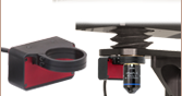
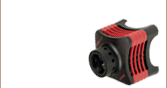
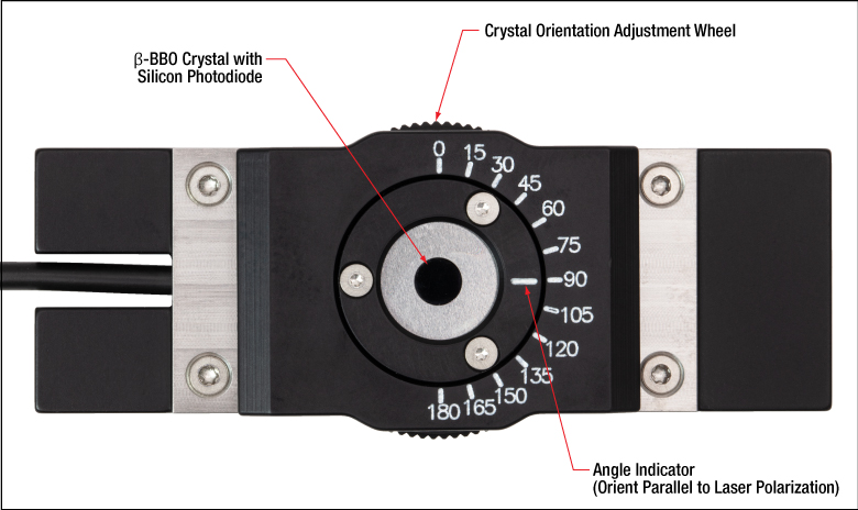
The NS170C sensor features a knurled phase adjustment wheel to tune the rotational orientation of the β-BBO crystal.
As shown in the photo to the left, the housing of the NS170C sensor features a knurled adjustment wheel to tune the angle between the light's polarization orientation and the β-BBO crystal's optical axis. At the entrance of the sensor is a 170 µm thick cover glass sealed to the sensor housing, allowing the sensor to be used with dry, water immersion, and oil immersion objectives. The working distance from the top of the cover glass to the β-BBO crystal is 0.22 mm. The back of the sensor housing features a laser-engraved alignment crosshair that marks the active sensor area to aid in aligning and focusing the beam.
Thorlabs recommends yearly recalibration of the NS170C sensor. Thorlabs offers a recalibration service for this photodiode sensor, which can be ordered below (see Item # CAL-NS). Recalibration of a single-channel power and/or energy meter console or interface is included with the recalibration of a sensor at no additional cost. For more information, please contact Tech Support.
For more information on the NS170C power sensor, please see the full presentation for our microscope slide peak power sensor for two-photon lasers.
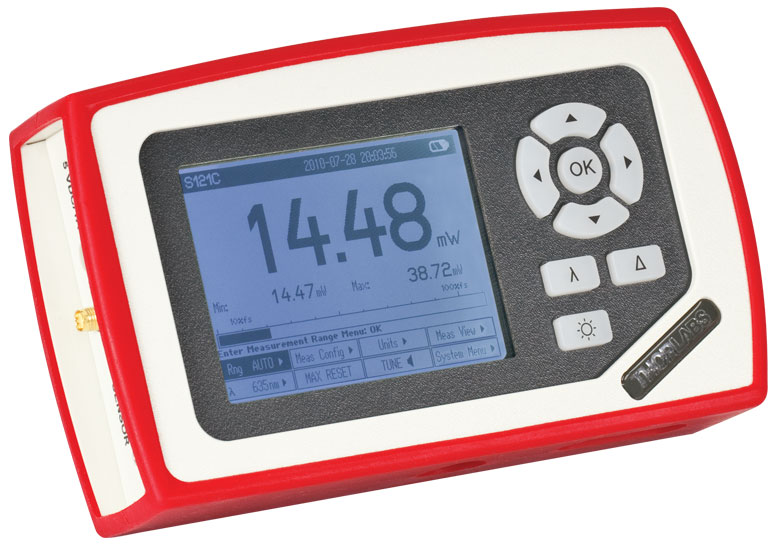
Our most popular power meter consoles are included here for convenience. The PM100D digital power meter console features a back-lit LED screen and includes a 1 GB external SD memory card. The PM400 touch screen power meter console can perform the same functions as the PM100D with added features that include storing past power measurements in its 4 GB internal memory, inputs for external temperature and humidity sensors, programmable GPIO ports, and a capacitive touchscreen display that allows the unit to be operated with multi-touch gestures. Additionally, the PM400 allows optical power measurement data, temperature logs, spectral correction curves, and attenuation correction data can be saved by the user and transfered between the console and an external device for further analysis. These functions are particularly useful for tracking the consistency of the power at the sample plane over time. For more information, click on the part number in the table below to view the complete presentation for each power meter console.
Alternatively, the S170C, S171C, S175C, and NS170C sensors are compatible with the PM5020 and the previous-generation PM200 and PM320E consoles. All three sensors can also be used with the PM100 series and PM100USB interfaces, which provide communication between the sensor and an external control unit such as a PC. Additionally, the S170C, S171C, and NS170C power sensors are compatible with the PM103 series interfaces and the S175C with the PM102 series interfaces.
| Item # | PM100A | PM100D | PM400 |
|---|---|---|---|
| Console Image (Click the Image to Enlarge) |
 |
 |
 |
| Display | Mechanical Needle and LCD Display with Digital Readout |
320 x 240 Pixel Backlit Graphical LCD Display |
Projected Capacitive Touchscreen with Color Display |
| Output | Analog Needle or Digital Numeric Readout | Numerical, Bar Graph, Statistics, Simulated Analog Needle |
Numerical with Bar Graph, Trend Graph (Power or Energy and Temperature), Statistics, Simulated Analog Needle |
| Calibration Functions | Wavelength Correctiona | Wavelength Correctiona | Wavelength Correctiona; Also Accepts User-Input Source Spectra and Attenuation Correction Data |
| Data Storage and Transfer | USB 2.0 Interface | 1 GB External SD Memory Card, USB 2.0 Interface |
4 GB Internal Memory Mini B USB 2.0 Interface |
| Dimensions | 7.24" x 4.29" x 1.61" (184 mm x 109 mm x 41 mm) |
7.09" x 4.13" x 1.50" (180 mm x 105 mm x 38 mm) |
5.35" x 3.78" x 1.16" (136.0 mm x 96.0 mm x 29.5 mm) |
| Display Dimensions | 1.9" x 0.5" (48.2 mm x 13.2 mm) Digital Display and 3.54" x 1.65" (90.0 mm x 42.0 mm) Analog Display |
3.17" x 2.36" (81.4 mm x 61.0 mm) |
3.7" x 2.1" (95 mm x 54 mm) |
| Calibration Service Item # |
Compatible Microscope Slide Power Sensor |
|---|---|
| CAL-PD | S170C and S171C |
| CAL-THPY | S175C |
| CAL-NS | NS170C |
Thorlabs offers recalibration services for our microsope slide power sensors. To ensure accurate measurements, we recommend recalibrating the sensors annually. Recalibration of a single-channel power and/or energy meter console or interface is included with the recalibration of a sensor at no additional cost. If you wish to calibrate one or more sensors with a dual-channel console, each sensor and console calibration service will need to be purchased individually.
Refer to the table to the right for the appropriate calibration service Item # that corresponds to your microscope slide power sensor.
Requesting a Calibration
Thorlabs provides two options for requesting a calibration:
- Complete the Returns Material Authorization (RMA) form. When completing the RMA form, please enter your name, contact information, the Part #, and the Serial # of the item being returned for calibration; in the Reason for Return field, select "I would like an item to be calibrated." All other fields are optional. Once the form has been submitted, a member of our RMA team will reach out to provide an RMA Number, return instructions, and to verify billing and payment information.
- Select the appropriate sensor calibration Item # below, enter the Part # and Serial # of the sensor that requires recalibration, and then Add to Cart. If you would like a console calibrated with your sensor, repeat this process for Item # CAL-PM1 or CAL-PM2 below, entering the console Item # and Serial #. A member of our RMA team will reach out to coordinate the return of the item(s) for calibration. Note that each console calibration Item # represents the cost of calibrating a console alone; if requesting a single-channel console calibration with a sensor calibration, the appropriate discount will be applied when your request is processed. Should you have other items in your cart, note that the calibration request will be split off from your order for RMA processing.
Please Note: To ensure your item being returned for calibration is routed appropriately once it arrives at our facility, please do not ship it prior to being provided an RMA Number and return instructions by a member of our team.
| Calibration Service Item # | Compatible Consoles & Interfaces |
|---|---|
| Single-Channel | |
| CAL-PM1 | PM100D, PM100A, PM400, PM100USB, PM101 Series, PM102 Series, PM103 Series |
| Dual-Channel | |
| CAL-PM2 | PM5020, Previous-Generation PM320E |
These recalibration services are for the power and/or energy meter electronics of our consoles and interfaces. To ensure accurate measurements, we recommend recalibrating annually. Recalibration of a single-channel console or interface is included with these sensor recalibration services at no additional cost. If you wish to calibrate one or more sensors with a dual-channel console, each sensor and console calibration service will need to be purchased individually. For more details on these recalibration services, please click the Documents (![]() ) icons below.
) icons below.
The table to the upper right lists the power and/or energy meter consoles and interfaces that can be calibrated using the CAL-PM1 and CAL-PM2 recalibration services.
Requesting a Calibration
Thorlabs provides two options for requesting a calibration:
- Complete the Returns Material Authorization (RMA) form. When completing the RMA form, please enter your name, contact information, the Part #, and the Serial # of each item being returned for calibration; in the Reason for Return field, select "I would like an item to be calibrated." All other fields are optional. Once the form has been submitted, a member of our RMA team will reach out to provide an RMA Number, return instructions, and to verify billing and payment information.
- Select the appropriate Item # below, enter the Part # and Serial # of the item that requires recalibration, and then Add to Cart. If you would like to calibrate one or more sensors with your console, repeat this process for the appropriate sensor recalibration service above, entering the console Item # and Serial #. A member of our RMA team will reach out to coordinate return of the item(s) for calibration. Note that each console calibration Item # represents the cost of calibrating a console alone; if requesting a single-channel console calibration with a sensor calibration, the appropriate discount will be applied when your request is processed. Should you have other items in your cart, note that the calibration request will be split off from your order for RMA processing.
Please Note: To ensure your item being returned for calibration is routed appropriately once it arrives at our facility, please do not ship it prior to being provided an RMA Number and return instructions by a member of our team.