 Products Home
Analog Handheld Laser Power Meter Console
- Power Meter for Laser Tuning Applications
- Compatible with Over 20 Photodiode and Thermal Sensors
- Digital and Analog Output
PM100A


Please Wait
| Item # | PM100A |
|---|---|
| Compatible Sensors | Photodiode and Thermal |
| Optical Power Rangea | 100 pW to 200 W |
| Available Sensor Wavelength Rangea | 185 nm - 25 μm |
| Display Refresh Rate | 20 Hz |
| Bandwidtha | DC - 100 kHz |
| Photodiode Sensor Rangeb | 50 nA - 5 mA |
| Thermopile Sensor Rangeb | 1 mV - 1 V |
| Power Meter Selection Guide |
|---|
| Sensors |
| Photodiode Power Sensors |
| Thermal Power Sensors |
| Thermal Position & Power Sensors |
| Pyroelectric Energy Sensors |
| Power Meter Consoles |
| Digital Handheld Console |
| Analog Handheld Console |
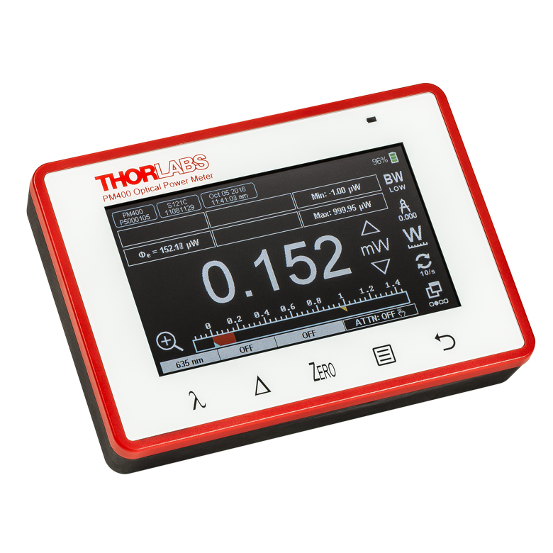
| Touchscreen Handheld Console |
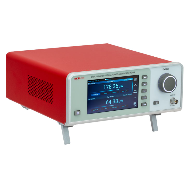
| Dual-Channel Benchtop Console |
| Complete Power Meters |
| Power Meter Bundles |
| Wireless Power Meters with Sensors |
| Compact USB Power Meters |
| Field Power Meters for Terminated Fibers |
| USB Interfaces, External Readout |
Features
- Combined Analog and Digital Power Meter Console
- Designed for Coherent and Incoherent Light Source Measurements
- Power Measurements for CW and Pulsed Source Detection
- Fast Mechanical Needle Display with 3 Scales
- Bright Graphics LCD Display with Different LCD Screens
- Numerical Display for Absolute Power Readouts
- Relative Measurement Screen for Power Tuning
- Statistics Screen with Display Hold
- Different Setup Screens for Configuration
- Versatile Functionality with Easy Handling:
- Min/Max Function
- Acoustic Tuning Sound with Max Hold Function
- Delta Mode Function
- Smart Sensor Connector for Quick Sensor Exchange
- USB 2.0 Interface
- Analog Output
- Sensor Upgrade and Recalibration Services Available
- Optical Power Monitor PC Software Available (See Software Tab for Details)
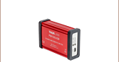
The PM100A power meter console is the analog counterpart to the PM100D digital power and energy meter. It offers top performance and reliability in a compact and portable console. The PM100A is ideal for use as a CW and pulsed laser power meter, incoherent optical source power meter, general light power meter, fiber power meter, and more. Depending on the connected sensor, it can measure optical power in the range from 100 pW to 200 W. The display on the PM100A features adjustable brightness settings, with the option to turn off the backlight completely while still being readable.
The PM100A is compatible with more than 20 photodiode, slim photodiode, integrating sphere, fiber, and thermal sensors designed for use from the UV to the Mid-IR. See the Sensor Selection tab for further information. When used together with a sensor from the compact S15xC Series of fiber sensors, the PM100A becomes a compact and portable fiber power meter that is ideal for field applications as well as in the lab.Thorlabs offers a variety of Power Meter Kits which include some of our most popular sensors bundled with the PM100A and PM100D consoles. Additionally it allows the connection of unamplified anode grounded photodiodes with up to 5 mA photocurrent and thermal elements with up to 1 V output voltage.
The PM100A is also available as a kit, bundled with our most popular sensors. Please visit our power meter kits page for more info. If you have any questions regarding these kits, or would like to suggest other kit options, please contact our Tech Support department for more details.
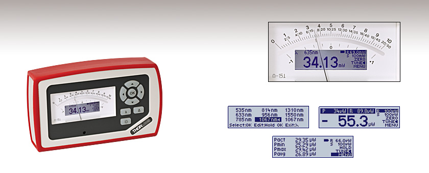
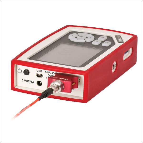
Console Design
The compact housing has a large analog needle display with three printed scales and front panel backlit button controls. In addition, the PM100A features a bright LCD screen that displays four different digital readouts: absolute power, relative power, statistics, and a configuration menu. Audio tuning is also featured.
A selectable bandwidth of either 20 Hz or 100 kHz offers more flexibility and adaptability to specific measurement tasks while using photodiode sensors. The higher bandwidth is optimal for pulse-detection; the lower bandwidth offers lower noise and better accuracy. Additionally, the power meter can adapt to the thermal time constant of thermal sensors leading to significantly faster measurements with thermal sensors. Thermal sensors have an individual time constant that can vary greatly from unit to unit. The PM100A now can adjust to this individual constant for each sensor and thus minimize the response time of the system (sensor + console).
Click to Enlarge
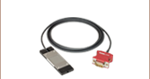
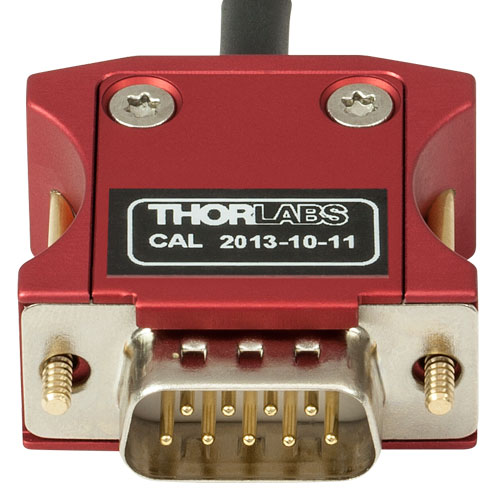
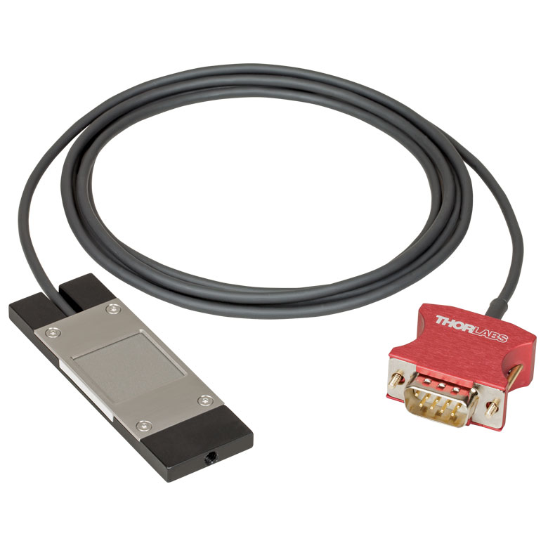
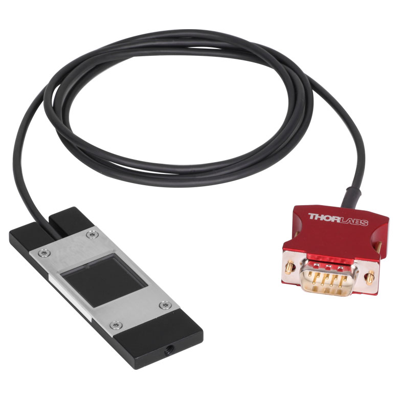
Thorlabs' C-Series Power Meter Sensor Connectors Include the Sensor Calibration Data
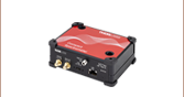
Connectivity
The sensor connector, shown to the left, enables "hot-swappable" quick sensor exchange and contains all the sensor information including NIST-traceable responsivity curves, sensor types, and model number.
Data can also be recorded via the USB PC connection and optical power monitor software. This software is capable of handling up to eight consoles simultaneously. The features of the PC control software are highlighted in the Software tab.
In addition to remote control operation and data logging/recording, the USB connection can also act as the charging system for the Li-Polymer battery. Also included is an AC battery charger which uses an intelligent charging management system to improve battery lifetime and reduce battery memory effects.
Recalibration Service
Recalibration services are available for our thermal and photodiode power sensors and consoles. We recommend your Thorlabs sensor and console be recalibrated as a pair; however, each may be recalibrated individually. To order this service for your sensor or console, scroll to the bottom of the page and select the appropriate recalibration service Item # that corresponds to your sensor or console. Recalibration of a single-channel console is included with the recalibration of a sensor at no additional cost.
Sensor Upgrade Service
Thorlabs' Sensors and PM100A Console are not compatible with old power meter consoles and sensor heads, respectively. We offer a sensor upgrade service if you want to use your existing sensors with a new power meter console. Note: upgraded sensors will be incompatible with old power meter consoles and new sensors converted to work with older consoles will not be compatible with the PM100A. Please contact our Tech Support team for details.
| Item # | PM100A |
|---|---|
| Display | |
| Display Type | Mechanical Analog Needle with Graphical LCD 132 x 32 pixels |
| Display Screens | Numerical, Relative Measurements, Tuning, Statistics, Mechanical Analog Needle |
| Viewing Area | 48.2 mm x 13.2 mm and 90.0 mm x 42.0 mm |
| Refresh Rate | 20 Hz |
| Backlit Display and Keypad | LED |
| Audio | Speaker |
| Sensor Interface | |
| Compatible Sensors | All Photodiodes, and Thermopiles See Below for Full Sensor Compatibility Specs |
| Time Constant Correction | 1 - 30 s |
| AD Converter | 16 bit |
| Connector | DB9F, Left Side |
| Sensor Temperature Control | Thermistor |
| Temperature Measurement Range | -10 to 80 °C |
| Analog Outputs | |
| Signal | Amplified Input Signal (Not Corrected) |
| Voltage Range | 0 to 2 V |
| Accuracy | ±3% |
| Bandwidth | Up to 100 kHz, Dependent on Sensor and Settings |
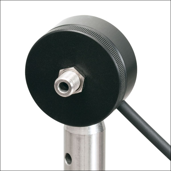
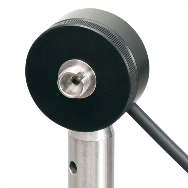
| Connector | SMA, Left Side |
| Digital Outputs | |
| Connector / Interface | Mini USB, USB2.0 |
| Power | |
| Battery | LiPolymer 3.7 V 1300 mAh |
| Charger / DC Input | 5 V / 1 A |
| Dimensions and Mounting | |
| Dimensions (LxWxH) | 183 mm x 109 mm x 40 mm |
| Weight | <0.5 kg |
| Mounting Options | Kickstand; 1/4"-20 Post Thread |
| Operating Temperature | 0 to 40 °C |
| Storage Temperature | -40 to 70 °C |
Sensor Compatibility Specs
| Item # | PM100A | |
|---|---|---|
| Detector Compatibility | Photodiode Sensors: S1xxC Series Photodiodes (Max 5 mA) |
Thermal Sensors: S3xxC Series Thermopiles (Max 1V) |
| Measurement Ranges | 6 Decades; 50 nA - 5 mA Ranges Selectable in W, Sensor Dependent |
4 Decades; 1 mV - 1 V Ranges Selectable in W, Sensor Dependent |
| Wavelength Ranges | 200 nm - 5500 nm | 190 nm - 25 μm |
| Power / Energy Ranges | 100 pW - 20 W | 10 μW - 200 W |
| Units | W, dBm, W/cm², A | W, dBm, W/cm², V |
| Accuracy | ±0.2% of Full Scale (5 µA - 5 mA) ±0.5% of Full Scale (50 nA) |
±0.5% of Full Scale (10 mV - 1 V) ±1% of Full Scale (1 mV) |
| Display Resolution | 1 pA / Responsivity Value (A/W) | 1 µV / Responsivity Value (V/W) |
| Bandwidth | DC - 100 kHz, Dependent on Sensor and Settings | DC - 10 Hz, Dependent on Sensor and Settings |
| Wavelength Correction | Sensor Dependent | Sensor Dependent |
For a full list of the sensor head specifications please visit the Photodiode Power Sensors and Thermal Power Sensors pages. For other information, please contact tech support.
| PM100A Display | |
|---|---|
| Standard Absolute Measurements | Relative Measurements |
 |  |
| This display shows the current absolute power values on both the mechanical needle and the LCD display. | Shows positive or negative power deviation from an initially zeroed position (needle in middle position). The offset and the absolute power value will be displayed in two sub displays in negative presentation. |
| Power Tuning with Sound Support | Statistics Screen |
 |  |
| This display shows the maximum reached power level. The level can be reset to the actual power level. | A display showing the current, min, max, and average power. All items can be reset to restart data sampling. |
| Wavelength Setting | |
 | |
| Configuration screen to set the wavelength of the incident beam. Easy switching between 9 user preconfigurable wavelengths. | |
PM100A Sensor Connectors
D-type Female
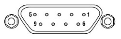
| Pin | Connection |
|---|---|
| 1 | +5 V (Drive max 50 mA from this pin) |
| 2 | EEPROM Digital I/O |
| 3 | Photodiode Ground (Anode), Thermal and Pyro Sensor Ground, Analog Ground |
| 4 | Photodiode Cathode |
| 5 | Pyro-Electric Sensor + |
| 6 | DGND |
| 7 | PRESENT (Connect this pin via a 1kΩ - 10kΩ resistor to Pin 3 (AGND)) |
| 8 | Thermal Sensor + |
| 9 | N.C. |
Analog Output
SMA Female
0 ... 2 V
Computer Connection
USB Type Mini-B
USB Type Mini-B to Type A Cable Included
Standard Photodiode Sensor Mounting Options
The compact design of Thorlabs' Standard Photodiode Sensors allows easy integration into existing setups. Typical mounting configurations including post, cage, and lens tube options are available. Shown on this page are several different choices for mounting these sensors.
The Standard Photodiode Sensors are compatible with all S120-xx series fiber adapters. FC/PC and SMA adapters are shown on the right. Adapters for FC/APC, SC, LC, and ST connections are also available.

Flip mounts are convenient for quick power measurements from a static location. The sensor can be placed in the path of the laser beam for the power measurement and flipped down during normal operation of the system.
FM90(/M) Right-Angle Flip Mounts are shown to the right. Thorlabs also offers the TRB1(/M) Articulating Post Mount. The lockable articulating mount offers almost unlimited positioning of the sensor head.

The Standard Photodiode Sensors also feature externally SM1-threaded connections on the front face. The SM1 threading provides easy mounting to 1" lens tube systems and quick release mounts.
Shown to the right are the KB1P(/M) Quick-Release Post Mount and QRC1A Quick-Release 30 mm Cage Mount. Both mounts feature SM1-threaded connections to the sensor heads.
Note: Due to the thickness of the S12xC sensor, the QRC1A and CP44F (shown below) quick-release mounts can only be fully removed from the cage system by backing them off an open end. The two mounts are easily removed from the cage system if only three cage rods are used. See the picture on the right.
Thorlabs also offers the CP44F 30 mm Cage Plates with Quick-Release Mounts. These mounts feature magnetically coupled front and back plates for easy and repeatable mounting.
Note: Like the QRC1A, the CP44F cannot be removed from a closed cage system.
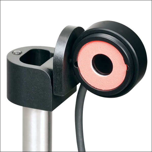
Slim Photodiode Sensor Mounting Options

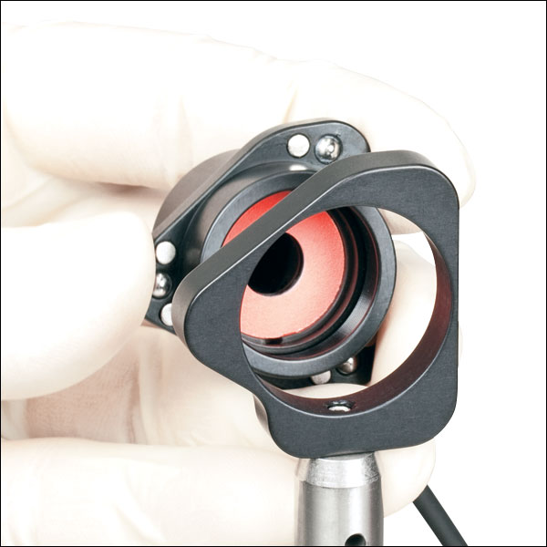
Thorlabs' Slim Photodiode Sensors are designed to fit into space-restricted environments such as 30 mm cage systems and optic-dense free-space arrangements.
Shown to the right is a S130C Sensor inserted into a 30 mm cage system. The application shown highlights the ease with which the sensor can be inserted into the cage, and the minimal space needed to take a power measurement.
The Slim Photodiode Sensors may also be mounted on a TRB1(/M) Articulating Mount. This mount allows repeatable insertion of the sensor into tight optic arrangements. After the measurement is made, the sensor may be rotated out of the beam path for normal operation.
Compact Slim Photodiode Sensor Mounting Options
Thorlabs' Compact Slim Photodiode Sensors are designed to fit into even tighter spaces such as 16 mm cage systems, our slotted Ø1/2" lens tubes, and other optic-dense free-space arrangements.
Shown to the right is an S116C Sensor inserted into a 16 mm cage system. The application shown highlights the ease with which the sensor can be inserted into the cage, and the minimal space needed to take a power measurement.
The compact slim photodiode sensor has two 8-32 (M4) taps for post mounting. One tap mounts the sensor horizontally, as seen to the right, and one allows it to be mounted vertically. The sensor may also be mounted on a TRB1(/M) Articulating Mount. This mount allows repeatable insertion of the sensor into tight optic arrangements. After the measurement is made, the sensor may be rotated out of the beam path for normal operation.
Microscope Slide Photodiode Sensor Mounting Options
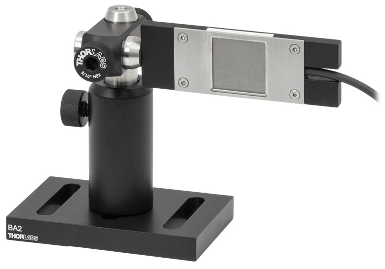
S170C Mounted on a Post
The S170C may be post mounted via the 8-32 (M4) tap in the side of the housing.
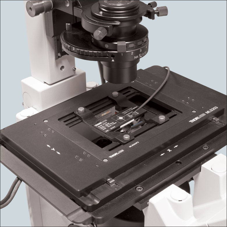
The S170C Microscope Slide Power Sensor is designed so that it can be mounted directly in a microscope slide holder. The 76.0 mm x 25.2 mm x 5.0 mm sensor head has the same footprint as a standard microscope slide and is compatible with most standard upright and inverted microscopes. The photo to the right shows the power sensor flipped over so that the engraved back of the housing can be used for alignment.
This power sensor also has an 8-32 (M4) tap for post mounting. In the photo to the far right, an RA90(/M) is used with two Ø1/2" posts to mount the sensor head in a horizontal orientation.
Integrating Sphere Photodiode Sensor Mounting Options

Thorlabs' Integrating Sphere Photodiode Sensor provides a low loss cavity for diverging, non-uniform, or off-axis beam measurements. These integrating spheres are ideal for all fiber-based applications due to the beam divergence at the end of the fiber.
Shown to the right is an S140C Integrating Sphere with S120-FC Fiber Adapter. Also shown is an S140C with an S140-BFA Bare Fiber Adapter. The Bare Fiber Adapter features a mounting clamp and light shield to decrease interference from ambient light.
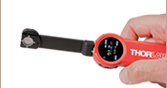
Compact Fiber Photodiode Sensor Mounting Options
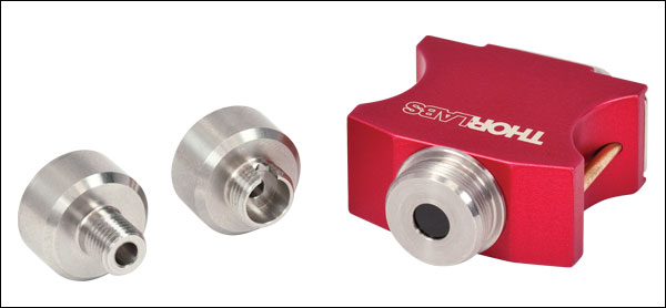
Thorlabs' Compact Fiber Photodiodes are the ideal choice for a portable, fiber-coupled power meter. The S15xC sensors are compatible with a wide variety of fiber connections. PM20-xx adapters are available to couple FC, APC, SMA, ST, SC, and LC connectors with the sensors. Shown to the right is an S150C Sensor with FC and SMA connector adapters.
Shown to the far right is a PM100D console with S150C sensor connected to a FC connectorized optical fiber. This setup is ideal for portable use in the lab or in the field.
Compatible Power Meters
- Consoles:
- PM100A Analog Power and Energy Meter Console
- PM100D Digital Power and Energy Meter Console
- PM400 Capacitive Touchscreen Power and Energy Meter Console
- PM5020 Dual-Channel Benchtop Optical Power and Energy Meter Console (Version 4.0 or Later)
- Complete Power Meters:
- PM160, PM160T, and PM160T-HP Wireless Handheld Power Meters with Bluetooth® Technology
- PM16 Series Compact USB Power Meters
- Interfaces:
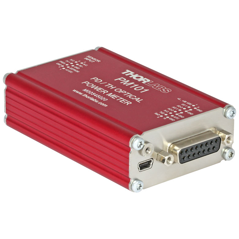
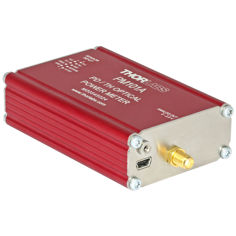
- PM101 Series Power Meter Interfaces with External Readout (Version 2.0 or Later)
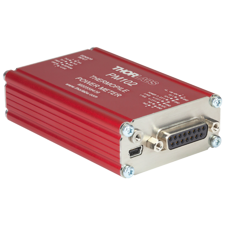
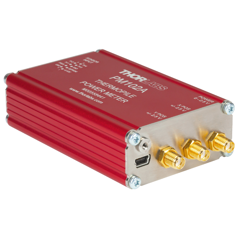
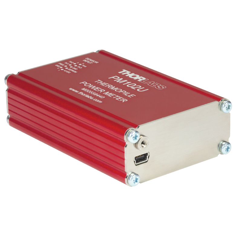
- PM102 Series Power Meter Interfaces with External Readout (Version 2.1 or Later)
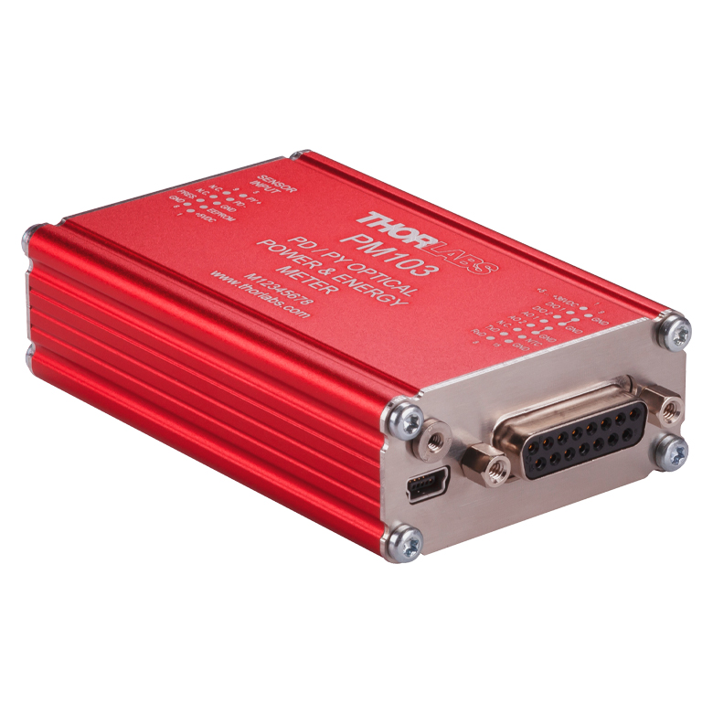
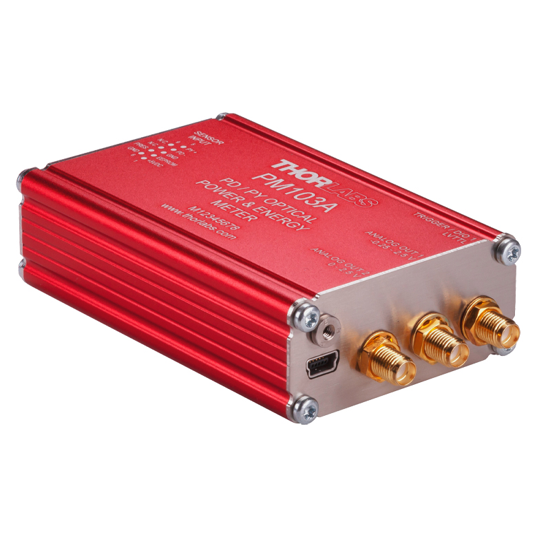
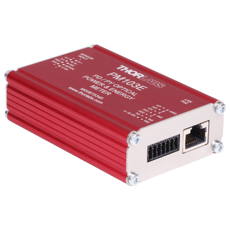
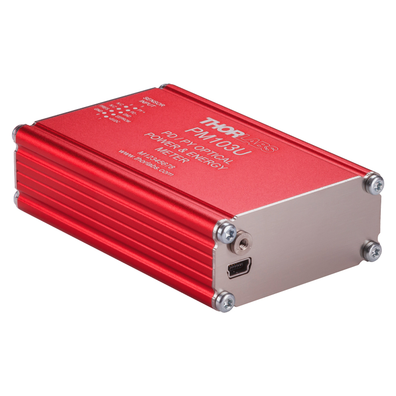
- PM103 Series Power Meter Interfaces with External Readout (Version 3.0 or Later)
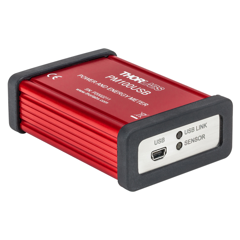
- PM100USB USB Interface Digital Power and Energy Meter
Optical Power Monitor
The Optical Power Monitor GUI software features power measurement, readout from up to eight power meters, and remote wireless operation.
For details on specific software features, please see the user manual.
Users interested in the legacy Power Meter Software can find it by visiting the software page.
The PM101 Series Power Meters are only compatible with version 2.0 or later. The PM102 Series Power Meters are only compatible with version 2.1 or later. The PM103 Series Power and Energy Meters are only compatible with version 3.0 or later. The PM5020 Console is only compatible with version 4.0 or later.
Optical Power Monitor GUI Software for Touchscreen, Handheld, and USB-Interface Power Meters
Features
- Operate up to Eight Power Meters Simultaneously
- Record and Analyze Measurements in Real Time
- Intuitive Analog Display and Graphing Modes
- Configurable Long-Term Data Logging
- Also Supports Position Measurements with Thermal Position & Power Sensors
- Compatible with USB and Bluetooth® Connections
The Optical Power Monitor software GUI enables seamless control of up to eight power meters that are connected via USB, RS232, or Bluetooth® wireless technologya. The latest software, firmware, drivers, and utilities for these power meters can be downloaded here.
Multiple data measurement and analysis functions are integrated into the GUI package. The interface offers a user-friendly design with minimal use of color and low brightness that is ideal use in dark lab environments while wearing laser safety glasses. Measured data can be displayed in real time as a simulated analog needle, digital values, line graph, or bar graph. Continuously logged and short-term measurements can be recorded for data viewing and analysis at a later point. A built-in statistics mode analyzes measured data and continuously updates to reflect new measurements within the pre-determined measurement period. Beam position measurements are also supported when used with our thermal position & power sensors.
The Optical Power Monitor software package installs the GUI, which then can be used to control the touchscreen, handheld, or USB-interface power meters. Firmware updates for supported power meters are also available. Programming examples and drivers for interfacing with our power and energy meter consoles using LabVIEW, C/C++, Visual C#, and Python are installed with the software; refer to the manual for details.
Please note that the Optical Power Monitor Software uses different drivers than the Power Meter Utilities Software and Thorlabs recommends using the new driver TLPM.dll. For users who wish to use the legacy Power Meter Software or use custom software designed using the older PM100D.dll driver, a Power Meter Driver Switcher program is included for easy swapping of the installed driver between the two versions.
a. The PM160, PM160T, and PM160T-HP power meters are equipped with Bluetooth® connections.
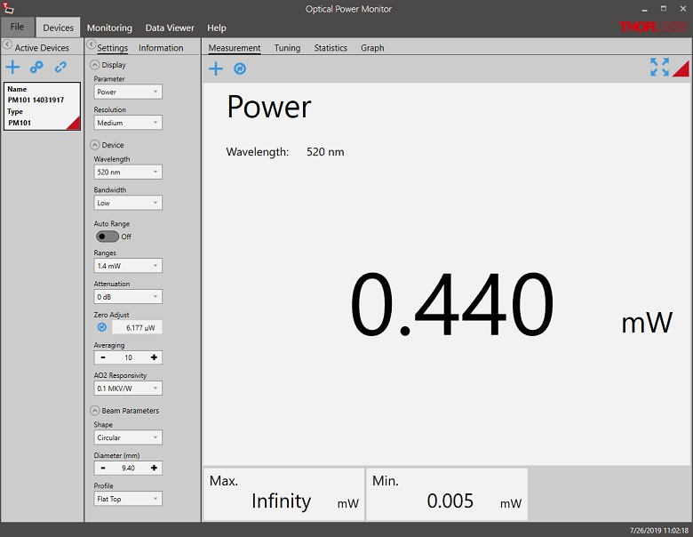
Click to Enlarge
Power Measurement Mode: Set up and configure up to eight power meters.
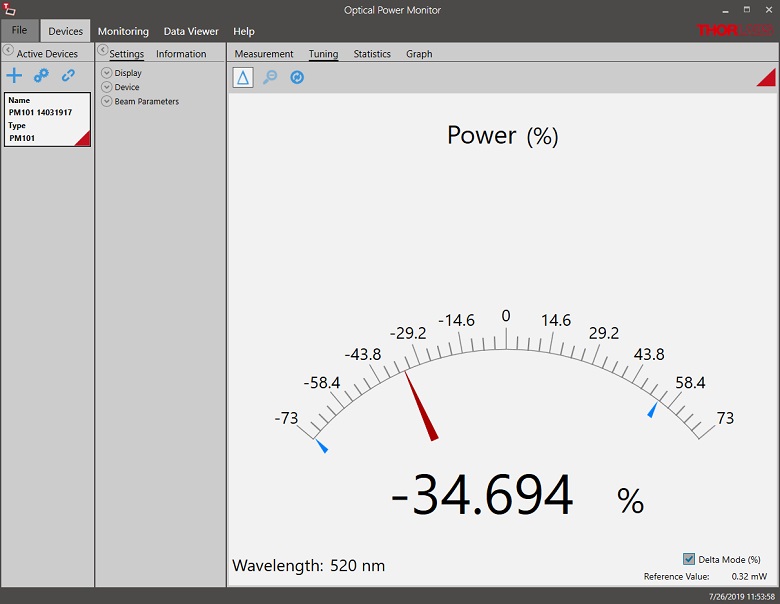
Click to Enlarge
Power Tuning Mode: Simulated analog needle and digital measurement value provided. Delta Mode, enabled above, shows the fluctuation range during the measurement period.
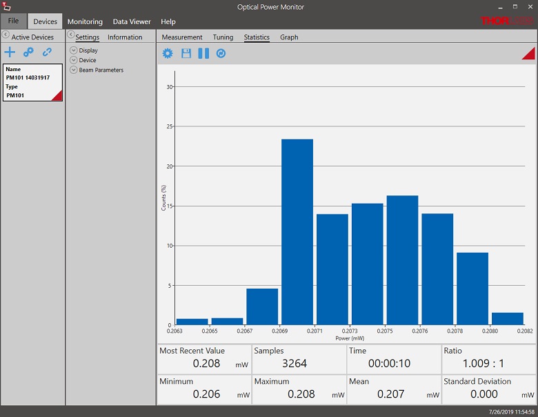
Click to Enlarge
Power Statistics Mode: Calculate numerical statistics for a pre-determined measurement period. The panel displays the analyzed values in a bar graph and the results as numerical values.
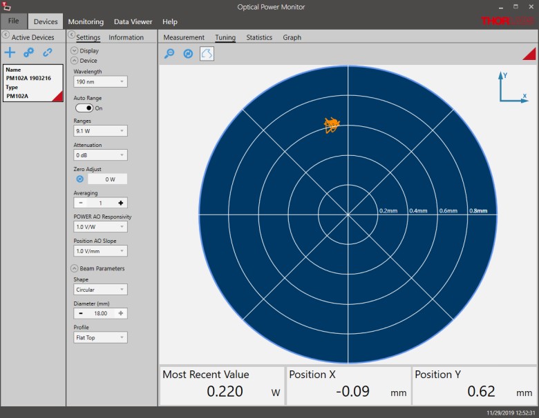
Click to Enlarge
Position Tuning Mode: Tuning mode can be used with a thermal position & power sensor to aid in beam alignment.
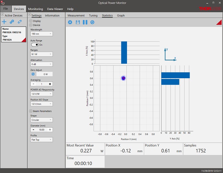
Click to Enlarge
Position Statistics Mode: Statistics mode also provides aggregate information for thermal position & power sensors.
Click to Enlarge
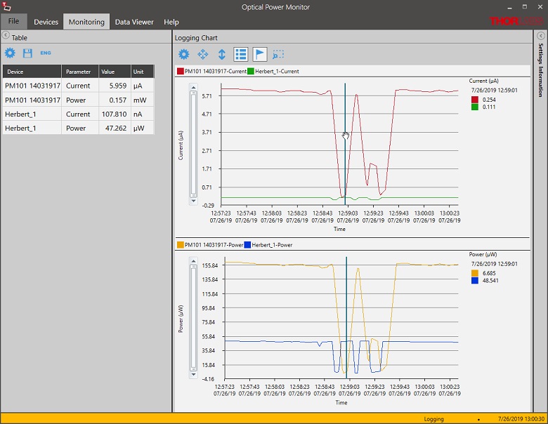
Data Logging: Enable long-term measurement and simultaneous recording from up to eight power meters. Save data as .csv files for later processing while measurement results are displayed in a graph in real time.
Click to Enlarge
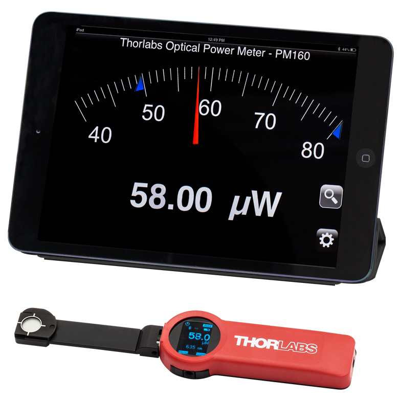
The PM160 wireless power meter, shown here with an iPad mini (not included), can be remotely operated using Apple mobile devices.
This tab outlines the full selection of Thorlabs' power and energy sensors. Refer to the lower right table for power meter console and interface compatibility information.
In addition to the power and energy sensors listed below, Thorlabs also offers all-in-one, wireless, handheld power meters and compact USB power meter interfaces that contain either a photodiode or a thermal sensor, as well as power meter bundles that include a console, sensor head, and post mounting accessories.
Thorlabs offers four types of sensors:
- Photodiode Sensors: These sensors are designed for power measurements of monochromatic or near-monochromatic sources, as they have a wavelength dependent responsivity. These sensors deliver a current that depends on the input optical power and the wavelength. The current is fed into a transimpedance amplifier, which outputs a voltage proportional to the input current.
- Thermal Sensors: Constructed from material with a relatively flat response function across a wide range of wavelengths, these thermopile sensors are suitable for power measurements of broadband sources such as LEDs and SLDs. Thermal sensors deliver a voltage proportional to the input optical power.
- Thermal Position & Power Sensors: These sensors incorporate four thermopiles arranged as quadrants of a square. By comparing the voltage output from each quadrant, the unit calculates the beam's position.
- Pyroelectric Energy Sensors: Our pyroelectric sensors produce an output voltage through the pyroelectric effect and are suitable for measuring pulsed sources, with a repetition rate limited by the time constant of the detector. These sensors will output a peak voltage proportional to the incident pulse energy.
| Console Compatibility | ||||||||
|---|---|---|---|---|---|---|---|---|
| Console Item # | PM100A | PM100D | PM400 | PM5020 | PM101 Series |
PM102 Series |
PM103 Series |
PM100USB |
| Photodiode Power |  |
|
|
|
|
- | |
|
| Thermal Power | |
|
|
|
|
|
- | |
| Thermal Position | - | - | |
|
- | |
- | - |
| Pyroelectric Energy | - | a |
a |
|
- | - | |
a |
Power and Energy Sensor Selection Guide
There are two options for comparing the specifications of our Power and Energy Sensors. The expandable table below sorts our sensors by type (e.g., photodiode, thermal, or pyroelectric) and provides key specifications.
Alternatively, the selection guide graphic further below arranges our entire selection of photodiode and thermal power sensors by wavelength (left) or optical power range (right). Each box contains the item # and specified range of the sensor. These graphs allow for easy identification of the sensor heads available for a specific wavelength or power range.
| Photodiode Power Sensors |
|---|


| Thermal Power Sensors |
|---|


| Thermal Position & Power Sensors |
|---|

| Pyroelectric Energy Sensors |
|---|


Sensor Options
(Arranged by Wavelength Range)
Sensor Options
(Arranged by Power Range)
| Posted Comments: | |
Kwanghee Hong
(posted 2021-07-15 11:01:36.377) Dear,
I'm user of PM30 power meter with S130A sensor.
Please supply power monitoring program via RS232 communication port.
Thanks wskopalik
(posted 2021-07-16 01:58:21.0) Thank you very much for your feedback!
I will contact you directly and send you the software for this power meter. Arturo Villegas
(posted 2020-06-12 10:33:03.63) Hello,
in our lab we have a PM100A(SN: P1001313). We want to read the measurements using matlab and yet not having found the way.
Is there any advice we can have from you on how to read the power with Matlab?
Thank you. MKiess
(posted 2020-06-16 11:13:50.0) This is a response from Michael at Thorlabs.I have contacted you directly to provide further support on this. user
(posted 2019-07-15 13:54:08.59) Hello, I have the same issue as "arcanbe" below.
Utility 5.9 does not detect the power meter under Win 10. The Instrument Communicator does not Show a valid entry either. The monitor Software works, but I Need to communicate with the device in a Visual Studio Project... swick
(posted 2019-07-24 04:47:12.0) Response from Sebastian at Thorlabs. In order to control the PM100A via Visual Studio I would recommend to use the TLPM driver. As you currently use Thorlabs Optical Power Monitor the power meter is currently assigned to TLPM driver (NI-VISA driver is outdated). The instrument communicator works with NI-VISA only and hence does not work when TLPM driver is assigned to the power meter.
When software package for the power meter is installed you should have the tool "Power Meter Driver Switcher" on the PC. You can use tool that to change assignment of the driver/device.
An example for Visual Studio with TLPM driver should be located at path:
C:\Program Files (x86)\IVI Foundation\VISA\WinNT\TLPM\Example
I contacted you directly to provide further assistance. dmytro.toptunov
(posted 2018-12-04 14:53:40.12) Hello,
We are looking for power meter to measure the average power output of the pulsed laser (tunable 750-1050 nm, 80 MHz rep. rate and 2.5W max average output power).
Am I correct that any of the S415C/S425C or S470C sensors with the appropriate console should work for us?
Another question: should we order calibration service together with the device, or it will come pre-calibrated?
Best regards,
Dmytro swick
(posted 2018-12-11 03:53:19.0) This is a response from Sebastian at Thorlabs. Thank you for the inquiry.
Without information about beam diameter and pulse width it is not possible to answer this question. The damage thresholds of the sensors need to be bigger than the energy density, average power density and peak power density from your laser system.
All our power meter sensors will be delivered pre-calibrated. ivanchenkocathrine
(posted 2018-10-24 08:58:53.413) hello.
Is it possible to use S305C with PM 100A?
Thanks swick
(posted 2018-10-29 04:55:46.0) This is a response from Sebastian at Thorlabs. Thank you for the inquiry.
The S305C and PM100A are compatible. matthieu.viteau
(posted 2018-10-01 13:14:01.003) Hi,
We have change our console to the old PM30 console and we realize we can't let the auto range, and is really annoying specially when we have a large power range (like fibre coupling optimisation). It's a way to solve this problem ?
Thanks nreusch
(posted 2018-10-03 06:54:37.0) This is a response from Nicola at Thorlabs. Thank you very much for your inquiry. To use the PM30 auto-range feature, you need to set the main function switch to "P" and press the multi control switch. Turning the multi control switch allows you to set the range manually. I will contact you directly to check whether you need further assistance. arcanbe
(posted 2016-06-17 21:41:17.57) Hi, I am having troubles when using the Optical Oper Meter Utility. The software does not detect my instrument. I have a PM100A. I am using windows 10 in my computer. I specifically trid with the 5.4 and 4.9 versions. shallwig
(posted 2016-06-20 11:21:57.0) This is a response from Stefan at Thorlabs. Thank you for your inquiry. I have contacted you directly to troubleshoot this. daniel.arnaldo
(posted 2015-09-23 17:47:30.327) Hi there,
is there a sensor, compatible with the PM100,capable of measuring average power of a laser source delivering short laser pulses of a few tens of ps, at several tens of Watts of average power? Thanks! shallwig
(posted 2015-09-24 06:14:14.0) This is a response from Stefan at Thorlabs. Thank you very much for your inquiry. For measuring the average power of pulsed lasers with short pulse lengths thermal sensors are the best choice. The peak power has to be lower than the damage threshold of the sensor. An overview of the thermal heads for the different power ranges can be found on our website here: http://www.thorlabs.de/newgrouppage9.cfm?objectgroup_id=3333
For the obsolete PM100 power meters we can offer these sensors with A connector configuration as specials. I will contact you directly to check your laser parameters in detail and which sensor is suited best. thomas.dreischer
(posted 2013-10-31 09:37:21.817) please can you provide a table or a curve that shows the effective bandwidth of the analog output for various optical power levels such as 1nW, 10nW, 100nW, 1uW, 10uW, 100uW, 1mW?
It would be useful to have such a bandwidth data in table or curve format available in the general spec sheet.
Thank you in advance! tschalk
(posted 2013-10-31 05:35:00.0) This is a response from Thomas at Thorlabs. Thank you very much for your inquiry. In the manual of the PM100A (http://www.thorlabs.com/thorcat/17600/PM100A-Manual.pdf) a table is provided which shows the analog output bandwidth for the different current ranges. This table can be found in section 7.3 Technical data. I will contact you directly with more detailed information. tschalk
(posted 2013-01-11 10:19:00.0) This is a response from Thomas at Thorlabs. Thank you very much for your inquiry. Thorlabs does offer replacement batteries and we will contact you directly with more detailed information. philip.starkey
(posted 2013-01-08 11:16:50.533) Hi Thorlabs, The battery in our (now pretty old) PM100A doesn't appear to charge any more. Would you consider selling replacement batteries? (I know they need to be soldered, which we are happy to do) If you won't sell them, could you point us in the direction of buying a 3rd party one? Thanks! tcohen
(posted 2012-05-25 09:54:00.0) Response from Tim at Thorlabs: Thank you for sharing your feedback. We will contact you directly to find out more information and diagnose the problem. cho
(posted 2012-05-25 05:45:16.0) Dear Sir or Madam We have a problem regarding the Thorlabs PM100A power meter: If we change the measurement range of the Thorlabs power meter the displayed power changes severe (although the optical power stays the same). I am looking forward to your answer. Kind regards jvigroux
(posted 2011-10-19 13:00:00.0) a response form Julien at Thorlabs: Dear Robert, thank you for your feedback. the minimum bandwidth setting is 10Hz. when using this bandwidth setting, the data will be averaged over 1000 values coming form the AD converter. I will contact you directly in order to discuss your application and see which approach (software or hardware) would be the best for you. robert.carlson
(posted 2011-10-18 14:13:31.0) Regarding the PM100A power meter, is there a user-selectable bandwidth that can be adjusted I have a case where the power fluctuates, and I want as long a time constant as possible is desirable (i.e., minimum bandwidth). What is the minimum BW possible? (Sensor being considered is integrating sphere S144C. The S302C thermopiles have a slow response, as desired, but are not sufficiently sensitive.)
Thanks! jvigroux
(posted 2011-03-11 10:16:00.0) A response from Julien at Thorlabs: Dear Jeremy, the driver contains a function called PM100D_startDarkAdjust that performs a dark current adjustment. In order to perform this procedure, you of course need to ensure that the sensor is properly darkened. During the procedure, the state can always be asked through the function PM100D_getDarkAdjustState. The value of the offset can, once this procedure is over, be read out with the function PM100D_getDarkOffset. the description of those functions can be found in ethe programmer's reference manual that is installed with the driver. The default installation path is C:\Program Files\IVI Foundation\VISA\WinNT\PM100D_Drv\manual\PM100D_Drv.html jeremy.tsiang
(posted 2011-03-10 09:45:27.0) Hi there,
I am trying to find a software command to ZERO the PM100A I have. Our building is quite old, and the temperature in the lab is inconsistent at best, so we can have a 5 degree difference between days and way more between seasons. I have read through every command in the driver but cant find one that does what Im looking for. I just want a software command equivalent to selecting the ZERO function. Does this exist? Thanks for your help.
Jeremy Tsiang |
Thorlabs offers a wide selection of power and energy meter consoles and interfaces for operating our power and energy sensors. Key specifications of all of our power meter consoles and interfaces are presented below to help you decide which device is best for your application. We also offer self-contained wireless power meters and compact USB power meters.
When used with our C-series sensors, Thorlabs' power meter consoles and interfaces recognize the type of connected sensor and measure the current or voltage as appropriate. Our C-series sensors have responsivity calibration data stored in their connectors. The console will read out the responsivity value for the user-entered wavelength and calculate a power or energy reading.
- Photodiode sensors deliver a current that depends on the input optical power and the wavelength. The current is fed into a transimpedance amplifier, which outputs a voltage proportional to the input current. The photodiode's responsivity is wavelength dependent, so the correct wavelength must be entered into the console for an accurate power reading. The console reads out the responsivity for this wavelength from the connected sensor and calculates the optical power from the measured photocurrent.
- Thermal sensors deliver a voltage proportional to the input optical power. Based on the measured sensor output voltage and the sensor's responsivity, the console will calculate the incident optical power.
- Energy sensors are based on the pyroelectric effect. They deliver a voltage peak proportional to the pulse energy. If an energy sensor is recognized, the console will use a peak voltage detector and the pulse energy will be calculated from the sensor's responsivity.
The consoles and interfaces are also capable of providing a readout of the current or voltage delivered by the sensor. Select models also feature an analog output.
Consoles
| Item # | PM100A | PM100D | PM400 | PM5020 |
|---|---|---|---|---|
| (Click Photo to Enlarge) | 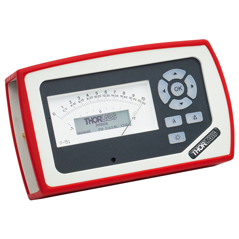 |
 |
 |
 |
| Key Features | Analog Power Measurements | Digital Power and Energy Measurements | Digital Power and Energy Measurements, Touchscreen Control | Dual Channel |
| Compatible Sensors | Photodiode and Thermal Power | Photodiode Power, Thermal Power, and Pyroelectric Energya | Photodiode Power, Thermal Power, Thermal Power and Position, and Pyroelectric Energya | Photodiode Power, Thermal Power, Thermal Power and Position, and Pyroelectric Energy |
| Housing Dimensions (H x W x D) |
7.24" x 4.29" x 1.61" (184 mm x 109 mm x 41 mm) |
7.09" x 4.13" x 1.50" (180 mm x 105 mm x 38 mm) |
5.35" x 3.78" x 1.16" (136.0 mm x 96.0 mm x 29.5 mm) |
9.97" x 4.35" x 11.56" (253.2 mm x 110.6 mm x 293.6 mm) |
| Channels | 1 | 2 | ||
| External Temperature Sensor Input (Sensor not Included) | - | - | Readout and Record Temperature Over Time | Readout and Record Temperature Over Time |
| External Humidity Sensor Input (Sensor not Included) | - | - | Readout and Record Humidity Over Time | Readout and Record Humidity Over Time |
| Input/Output Ports | - | 4 GPIO, Programmable | 4 Configurable Digital I/O Channels | |
| Shutter Control | - | - | - | Support for SH05R(/M) or SH1(/M) Optical Shutter with Interlock Input |
| Fan Control | - | - | - | |
| Source Spectral Correction | - | - | ||
| Attenuation Correction | - | - | ||
| External Trigger Input | - | - | - | |
| Display | ||||
| Type | Mechanical Needle and LCD Display with Digital Readout | 320 x 240 Pixel Backlit Graphical LCD Display | Protected Capacitive Touchscreen with Color Display | |
| Dimensions | Digital: 1.9" x 0.5" (48.2 mm x 13.2 mm) Analog: 3.54" x 1.65" (90.0 mm x 42.0 mm) |
3.17" x 2.36" (81.4 mm x 61.0 mm) |
3.7" x 2.1" (95 mm x 54 mm) |
4.32" x 2.43" (109.7 mm x 61.6 mm) |
| Refresh Rate | 20 Hz | 10 Hz (Numerical) 25 Hz (Analog Simulation) |
25 Hz | |
| Measurement Viewsb | ||||
| Numerical | ||||
| Mechanical Analog Needle | - | - | - | |
| Simulated Analog Needle | - | |||
| Bar Graph | - | |||
| Trend Graph | - | |||
| Histogram | - | - | - | |
| Statistics | ||||
| Memory | ||||
| Type | - | SD Card | NAND Flash | SD Card |
| Size | - | 2 GB | 4 GB | 8 GB |
| Power | ||||
| Battery | LiPo 3.7 V 1300 mAh | LiPo 3.7 V 2600 mAh | - | |
| External | 5 VDC via USB or Included AC Adapter | 5 VDC via USB | Line Voltage: 100 - 240 V | |


 Zoom
Zoom- Compact, Handheld, Analog Needle, Power Meter Console
- Digital Display Screen
- Long-Life Internal Li-Polymer Battery
- Console comes Calibrated with Certificate of Calibration
- 1 GB USB Memory Stick with Software including LabVIEW™ and LabWINDOWS™ /CVI Driver Set, and Operating Manual
Please note that sensors are not included with the PM100A console. For information about our compatible sensors, please see the sensor descriptions below. Thorlabs does offer a variety of Power Meter Kits with the PM100A Console bundled with several of our most popular sensors. Please visit our Power Meter Kits page for more details.
Thorlabs offers a recalibration service for the PM100A, which can be ordered below (see Item # CAL-PM1). Alternatively, if you have a corresponding sensor that needs recalibrating, you can include the PM100A with the sensor for recalibration at no additional cost. To order this service, scroll to the bottom of the page and select the appropriate Item # that corresponds to your sensor.
Click to Enlarge
S120C and CP44F Quick-Release Mount
- For General Purpose Optical Power Measurements
- Integrated Viewing Target for Easy Sensor Alignment
- Ø9.5 mm Sensor Aperture
- Sensor, Protective Cap, IR Target, and Thread Adapter Included
- Fiber Adapters Available Separately (See Table Below)
- See the Full Web Presentation for More Information
These Standard Photodiode Power Sensors are ideal for metering low power coherent and incoherent sources from the UV to the NIR. Each NIST-Traceable, calibrated sensor features an integrated viewing target for easy alignment, enhanced shielding against electromagnetic interference, an over-temperature-alert device, and a large Ø9.5 mm sensor aperture. The sensors are compatible with 30 mm cage systems, Ø1/2" posts, and SM1 (1.035"-40) lens tubes, and are ideal for free-space and fiber-coupled sources.
Thorlabs offers a recalibration service for these photodiode power sensors, which can be ordered below (see Item # CAL-UVPD for UV-extended Si sensors, Item # CAL-PD for Si sensors and Item # CAL-IRPD for Ge sensors).
| Item #a | S120VC | S120C | S121C | S122Ch |
|---|---|---|---|---|
| Sensor Image (Click the Image to Enlarge) |
|
|
|
|
| Aperture Size | Ø9.5 mm | |||
| Wavelength Range | 200 - 1100 nm | 400 - 1100 nm | 400 - 1100 nm | 700 - 1800 nm |
| Power Range | 50 nW - 50 mW | 500 nW - 500 mW | 50 nW - 40 mW | |
| Detector Type | Si Photodiode (UV Extended) | Si Photodiode | Ge Photodiode | |
| Linearity | ±0.5% | |||
| Resolutionb | 1 nW | 10 nW | 2 nW | |
| Measurement Uncertaintyc | ±3% (440 - 980 nm) ±5% (280 - 439 nm) ±7% (200 - 279 nm, 981 - 1100 nm) |
±3% (440 - 980 nm) ±5% (400 - 439 nm) ±7% (981 - 1100 nm) |
±5% | |
| Responsivityd (Click for Plot) |  Raw Data |
 Raw Data |
 Raw Data |
 Raw Data |
| Coating/Diffuser | Reflective ND (OD1.5)e | Reflective ND (OD1)f | Reflective ND (OD2)g | Absorptive ND (Schott NG9) |
| Head Temperature Measurement | NTC Thermistor 4.7 kΩ | |||
| Housing Dimensions | Ø30.5 mm x 12.7 mm | |||
| Cable Length | 1.5 m | |||
| Post Mountinge,f,g | Universal 8-32 / M4 Tap, Post Not Included | |||
| Aperture Thread | External SM1 (1.035"-40) | |||
| Compatible Fiber Adapters | S120-FC2, S120-FC, S120-APC2, S120-APC, S120-SMA, S120-ST, S120-LC, and S120-SC (Not Included) | |||
| Compatible Consoles | PM400, PM100D, PM100A, and PM5020 | |||
| Compatible Interfaces | PM101, PM101A, PM101R, PM101U, PM103, PM103A, PM103E, PM103U, and PM100USB | |||
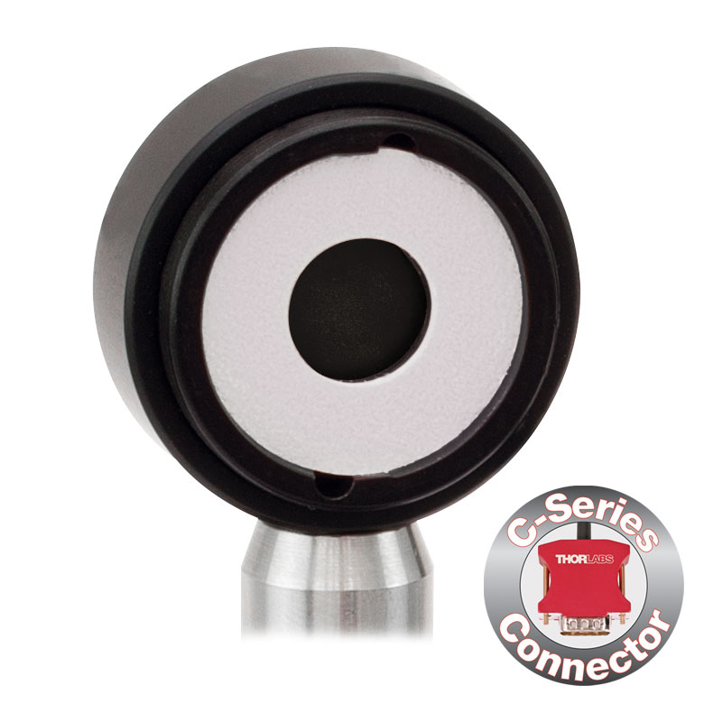

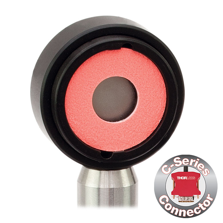


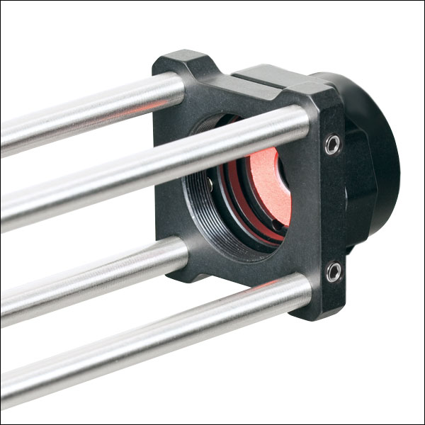
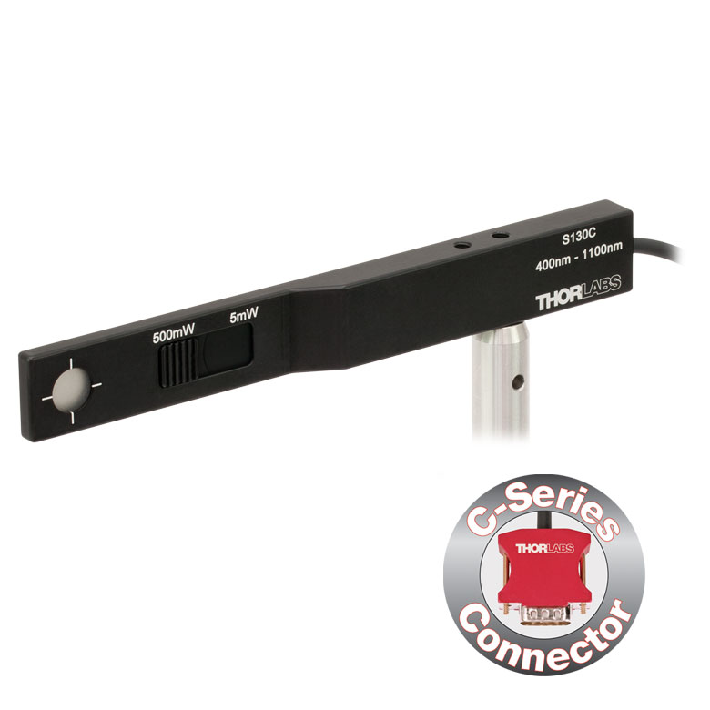
Click for Details S130C Photodiode Sensor Mounted in FiberBench System Using FBSM Mount
- For Optical Power Measurements in Confined Spaces
- Very Slim Design: 5 mm Thin on Sensor Side
- Ø9.5 mm Sensor Aperture
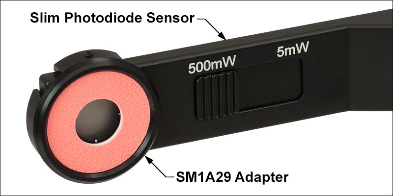
- Slideable ND Filter Automatically Changes Sensor Power Range
- Optional SM1A29 Adapter with VIS/IR Target and External SM1 Threading (More Details)
- Optional FBSM Mount with VIS/IR Target for FiberBench Systems (More Details)
- See the Full Web Presentation for More Information
These Slim Photodiode Power Sensors are designed to take optical source power measurements in locations where space and accessibility are at a premium. The 5 mm thin sensor end can fit between closely spaced optics, cage systems, and other arrangements where standard power meters may not fit. The NIST-Traceable, calibrated sensors also feature a large Ø9.5 mm sensor aperture and slideable neutral density filter for dual power ranges in one compact device.
A separately available SM1A29 adapter can be attached by 2 setscrews to any S130 series power sensor to mount fiber adapters, light shields, filters or any other SM1-threaded (1.035"-40) mechanics or optics. The FBSM Mount allows our S130 series power sensors to be mounted vertically into FiberBench systems for stable mounting with a minimal footprint.
Thorlabs offers a recalibration service for these photodiode power sensors, which can be ordered below (see Item # CAL-UVPD2 for UV-extended Si sensors, Item #CAL-PD2 for Si sensors, and Item # CAL-IRPD2 for Ge sensors).
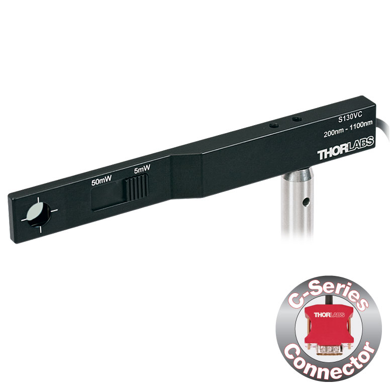
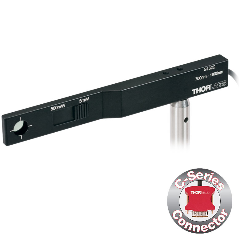
| Item #a | S130VC | S130C | S132C | |
|---|---|---|---|---|
| Sensor Image (Click the Image to Enlarge) |
|
|
|
|
| Aperture Size | Ø9.5 mm | |||
| Wavelength Range | 200 - 1100 nm | 400 - 1100 nm | 700 - 1800 nmb | |
| Power Range (with Filter) |
500 pW - 0.5 mWc (Up to 50 mW)c |
500 pW - 5 mW (Up to 500 mW) |
5 nW - 5 mW (Up to 500 mW) |
|
| Detector Type | Si Photodiode (UV Extended) | Si Photodiode | Ge Photodiode | |
| Linearity | ±0.5% | |||
| Resolution | 100 pWd | 1 nWe | ||
| Measurement Uncertaintyf | ±3% (440 - 980 nm) ±5% (280 - 439 nm) ±7% (200 - 279 nm, 981 - 1100 nm) |
±3% (440 - 980 nm) ±5% (400 - 439 nm) ±7% (981 - 1100 nm) |
±5% | |
| Responsivityg (Click for Plot) | Raw Data |
Raw Data |
Raw Data |
|
| Coating/Diffuser | Reflective ND (OD1.5)c | Reflective ND (OD2)h | Absorptive ND (Schott NG9/KG3)b | |
| Housing Dimensions | 150 mm x 19 mm x 10 mm; 5 mm Thickness on Sensor Side | |||
| Cable Length | 1.5 m | |||
| Post Mounting | 8-32 and M4 Taps | |||
| Adapters (Not Included) | SM1A29: Add SM1 Thread and Viewing Target to Aperture Fiber Adapters Compatible with SM1A29 Adapter: S120-FC2, S120-FC, S120-APC2, S120-APC, S120-SMA, S120-ST, S120-SC, and S120-LC FBSM: Integrate Sensor into FiberBench Setups |
|||
| Compatible Consoles | PM400, PM100D, PM100USB, PM100A, and PM5020 | |||
| Compatible Interfaces | PM101, PM101A, PM101R, PM101U, PM103, PM103A, PM103E, PM103U, and PM100USB | |||
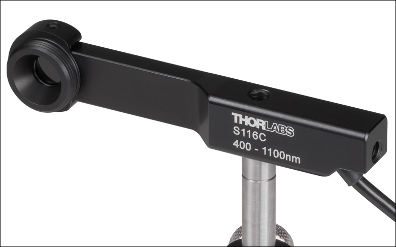
| Item #a | S116C | |
|---|---|---|
| Sensor Image (Click the Image to Enlarge) |
|
|
| Aperture Size | Ø6 mm | |
| Wavelength Range | 400 - 1100 nm | |
| Power Range | 20 nW - 50 mW | |
| Detector Type | Si Photodiode | |
| Linearity | ±0.5% | |
| Resolution | 1 nWb | |
| Measurement Uncertaintyc | ±3% (451 - 1000 nm) ±5% (400 - 450 nm, 1001 - 1100 nm) |
|
| Responsivityd (Click for Plot) |
Raw Data |
|
| Coating/Diffuser | Absorptive ND (NG9) | |
| Housing Dimensions (L x W x T) |
70.0 mm x 11.0 mm x 8.9 mm; 10.0 mm Width and 4.5 mm Thickness on Sensor Side |
|
| Active Detector Area | 7 mm x 7 mm | |
| Cable Length | 1.5 m | |
| Mounting Threads | 2 Universal 8-32 / M4 Taps (One on the Back, One on the Bottom), Posts Not Included |
|
| Adapters (Not Included) |
SM05A29: Add SM05 Thread to Aperture Fiber Adapters Compatible with SM05A29 Adapter: PM20-FC2, PM20-FC, PM20-APC2, PM20-APC, PM20-SMA, PM20-ST, PM20-SC, and PM20-LC |
|
| Compatible Consoles | PM400, PM100D, PM100A, and PM5020 | |
| Compatible Interfaces | PM101, PM101A, PM101R, PM101U, PM103, PM103A, PM103E, PM103U, and PM100USB | |
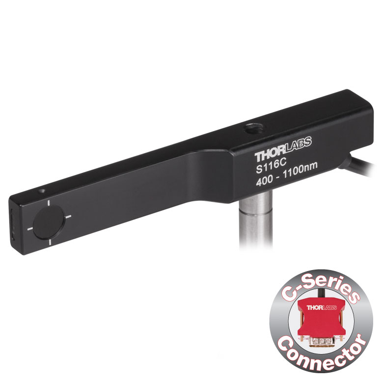
- For Optical Power Measurements in Tiny Spaces Such as 16 mm Cage Systems
- Wavelength Range: 400 - 1100 nm
- Very Slim Design: 10.0 mm Wide and 4.5 mm Thin on Sensor Side
- Silicon Photodiode with Ø6 mm Sensor Aperture
- Designed for Power Measurements for Low Power Lasers
- Post Mountable via 8-32 (M4) Taps
- SM05A29 Adapter with External SM05 (0.535"-40) Threading Available Separately (More Details)
- See the Full Web Presentation for More Information
The S116C Compact Slim Photodiode Power Sensor is designed to take optical source power measurements in locations where space and accessibility are at a premium. The 4.5 mm thin photodiode sensor can fit between the rods of a 16 mm cage system, as seen in the application photo below, as well as through the side openings of our slotted Ø1/2" lens tubes (Item #s SM05L20C and SM05L30C). This sensor also features a Ø6 mm sensor aperture.
A separately available SM05A29 adapter can be attached by two 0.05" (1.3 mm) hex setscrews to an S116C power sensor to mount fiber adapters, light shields, filters or any other SM05-threaded (0.535"-40) mechanics or optics. The adapter mounted on the S116C power sensor is shown below.
Each sensor is shipped with NIST- and PTB-traceable calibration data. The included data is determined with the help of a certified reference diode, which corresponds to the spectral range of the sensor to be calibrated. Thorlabs offers a recalibration service for these photodiode power sensors, which can be ordered below (see Item # CAL-PD for Si sensors).
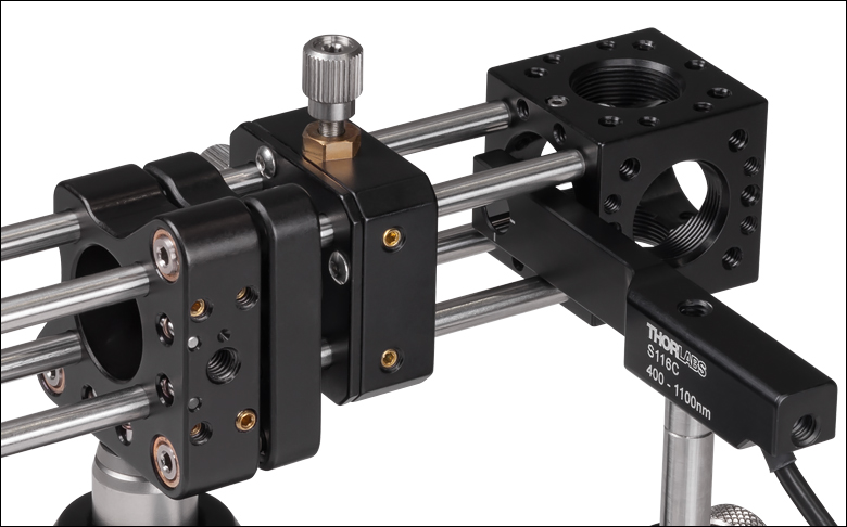
Click to Enlarge S116C Sensor in a 16 mm Cage System
| Item #a | S170C | S171C | |||
|---|---|---|---|---|---|
| Sensor Image (Click Image to Enlarge) |
 |
 |
|||
| Overall Dimensions | 76.0 mm x 25.2 mm x 5.0 mm (2.99" x 0.99" x 0.20") |
||||
| Active Detector Area | 18 mm x 18 mm | ||||
| Input Aperture | 20 mm x 20 mm | ||||
| Wavelength Range | 350 - 1100 nm | 400 - 1100 nm | |||
| Optical Power Working Range | 10 nW - 150 mW | 1 nW - 15 mW | |||
| Detector Type | Silicon Photodiode | ||||
| Linearity | ±0.5% | ||||
| Resolution | 1 nWb | 0.5 pWc | |||
| Measurement Uncertaintyd | ±3% (440 - 980 nm) ±5% (350 - 439 nm) ±7% (981 - 1100 nm) |
±3% (440 - 980 nm)e ±5% (400 - 439 nm)e ±7% (981 - 1100 nm)e |
|||
| Responsivityf (Click for Plot) |
Raw Data |
Raw Data |
|||
| Neutral Density Filter | Reflective (OD 1.5) | Absorptive (OD 0.4) | |||
| Cable Length | 1.5 m | ||||
| Mounting Thread | Universal 8-32 / M4 Tap, Post Not Included | ||||
| Compatible Consoles | PM400, PM100D, PM100A, and PM5020 | ||||
| Compatible Interfaces | PM101, PM101A, PM101R, PM101U, PM103, PM103A, PM103E, PM103U, and PM100USB | ||||
- Designed to Measure Optical Power at the Sample Plane of a Microscope
- Silicon Photodiode with Large 18 mm x 18 mm Active Area
- Sensor Housing Dimensions: 76.0 mm x 25.2 x 5.0 mm
- Index Matching Gel Utilized in Design to Prevent Internal Reflections
- Information Stored in Connector
- Sensor Data
- NIST- and PTB-Traceable Calibration Data
- Post Mountable via 8-32 (M4) Tap
The Microscope Slide Power Sensor Heads with silicon photodiodes are designed to measure the power at the sample plane in microscopy setups. The S170C sensor can detect wavelengths from 350 nm to 1100 nm at optical powers from 10 nW to 150 mW, while the S171C sensor can detect wavelengths from 400 nm to 1100 nm at powers from 1 nW to 15 mW. Each sensor head's 76.0 mm x 25.2 mm footprint matches that of a standard microscope slide and is compatible with most standard upright and inverted microscopes.
The photodiodes have 18 mm x 18 mm active areas and are contained in sealed housings behind neutral density (ND) filters. A 20 mm x 20 mm indentation around the surface of the ND filter is sized to accept standard microscope cover slips. An immersion medium (water, glycerol, oil) may be placed in this well directly over the ND filter, or a cover slip may be inserted first to simplify clean up. The gap between the photodiode and the neutral density filter has been filled with an index matching gel in order to prevent internal reflections from causing significant measurement errors when using high NA objectives with oil or water.
The bottom of each sensor housing features a laser-engraved grid to aid in aligning and focusing the beam. In standard microscopes, this grid can be used for beam alignment before flipping the sensor head to face the objective for power measurements. In inverted microscopes, turn on the transmitted illuminator to align the grid on the detector housing with the beam, thereby centering the sensor in front of the objective. Alternatively, the diffusive surface of the ND filter can be used as a focusing plane.
To avoid damaging the sensor, we recommend positioning it in the light path at a location where the beam is not focused. It is important not to exceed the Max Average Power Density (see Specs tab) over the beam's spot size.
Each sensor is shipped with NIST- or PTB-traceable calibration data. The included data will match the calibration certification of the photodiode used to test the individual sensor. Sensor specifications and the included NIST- or PTB-traceable calibration data are stored in non-volatile memory in the sensor connector and can be read out by the latest generation of Thorlabs power meters. We recommend yearly recalibration to ensure accuracy and performance. Calibration may be ordered using the CAL-PD recalibration service available below. Please contact technical support for more information.
Thorlabs also offers a Microscope Slide Sensor Head with a thermal sensor; the full presentation can be found here.
| Item #a | S175C |
|---|---|
| Sensor Image (Click Image to Enlarge) |
 |
| Active Detector Area | 18 mm x 18 mm |
| Wavelength Range | 0.3 - 10.6 µm |
| Power Range | 100 µW - 2 W |
| Detector Type | Thermal Surface Absorber (Thermopile) |
| Linearity | ±0.5% |
| Resolutionb | 10 µW |
| Measurement Uncertaintyc | ±3% @ 1064 nm; ±5% @ 300 nm - 10.6 µm |
| Response Time | 3 s (<2 s from 0 to 90%) |
| Housing Dimensions | 76 mm x 25.2 mm x 4.8 mm (2.99" x 0.99" x 0.19") |
| Cable Length | 1.5 m |
| Housing Features | Integrated Glass Cover Engraved Laser Target on Back |
| Post Mounting | N/A |
| Cage Mounting | N/A |
| Aperture Thread | N/A |
| Compatible Consoles | PM400, PM100D, PM100A, and PM5020 |
| Compatible Interfaces | PM101, PM101A, PM101R, PM101U, PM102, PM102A, PM102U, and PM100USB |
Click to Enlarge
Typical absorption curve for the S175C (glass and absorber). Note that this curve is representative, and the actual absorption across the spectrum will vary from unit to unit.

Click to Enlarge
The back of the S175C housing is engraved with the sensor specifications and a target for centering the beam on the sensor.
- Wavelength Range: 300 nm - 10.6 µm
- Sensitive to Optical Powers from 100 µW to 2 W
- Designed to Measure Optical Power in the Sample Plane of a Microscope
- Thermal Sensor with 18 mm x 18 mm Active Area
- 76.0 mm x 25.2 mm Footprint Matches Standard Microscope Slides
- Information Stored in Connector
- Sensor Data
- NIST- and PTB-Traceable Calibration Data
- See the Full Web Presentation for More Information
The S175C Microscope Slide Thermal Power Sensor Head is designed to measure the power at the sample in microscopy setups. The thermal sensor can detect wavelengths between 300 nm and 10.6 µm at optical powers between 100 µW and 2 W. The sensor head's 76.0 mm x 25.2 mm footprint matches that of a standard microscope slide and is compatible with most standard upright and inverted microscopes.
The thermal sensor has an 18 mm x 18 mm active area and is contained in a sealed housing behind a glass cover. An immersion medium (water, glycerol, oil) may be placed over the glass cover plate.
As seen in the image to the right, the bottom of the sensor housing features a laser-engraved target to aid in aligning and focusing the beam. In standard microscopes, the target can be used for beam alignment before flipping the sensor head to face the objective for power measurements. In inverted microscopes, turn on the trans-illumination lamp and align the target on the detector housing with the beam; this will center the sensor in front of the objective.
Sensor specifications and the NIST- and PTB-traceable calibration data are stored in non-volatile memory in the sensor connector and can be read out by the latest generation of Thorlabs power meters. We recommend yearly recalibration to ensure accuracy and performance. Calibration may be ordered using the CAL-THPY recalibration service available below. Please contact technical support for more information.
Thorlabs also offers a Microscope Slide Sensor Head with a photodiode sensor for low-power, high-resolution measurements; the full presentation may be found here.
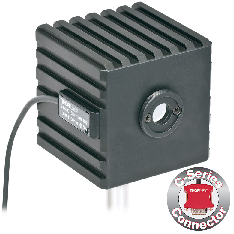
Click to Enlarge
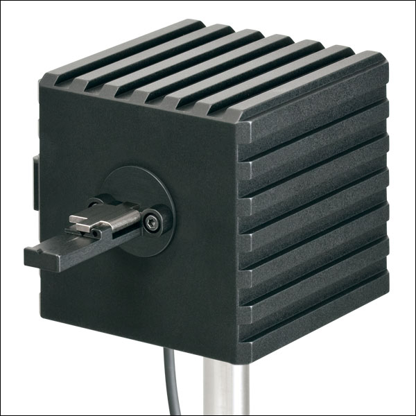
S142C and S140-BFA Bare Fiber Adapter (Sold Separately)
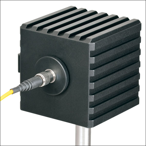
Click to Enlarge
S142C with the S120-FC Fiber Adapter (Included)
- For Measurements Independent of Beam Shape and Entrance Angle
- Integrating Sphere Design Acts as a Diffuser with Minimal Power Loss
- Ø5 mm, Ø7 mm, Ø12 mm, or Ø22 mm Input Sensor Aperture
- Spheres with Apertures ≤Ø12 mm Include a Removable S120-FC Fiber Adapter (FC/PC and FC/APC)
- Fiber Adapters for Terminated and Bare Fiber (See Table Below) are Compatible with Spheres with Apertures ≤Ø12 mm
- See the Full Web Presentation for More Information
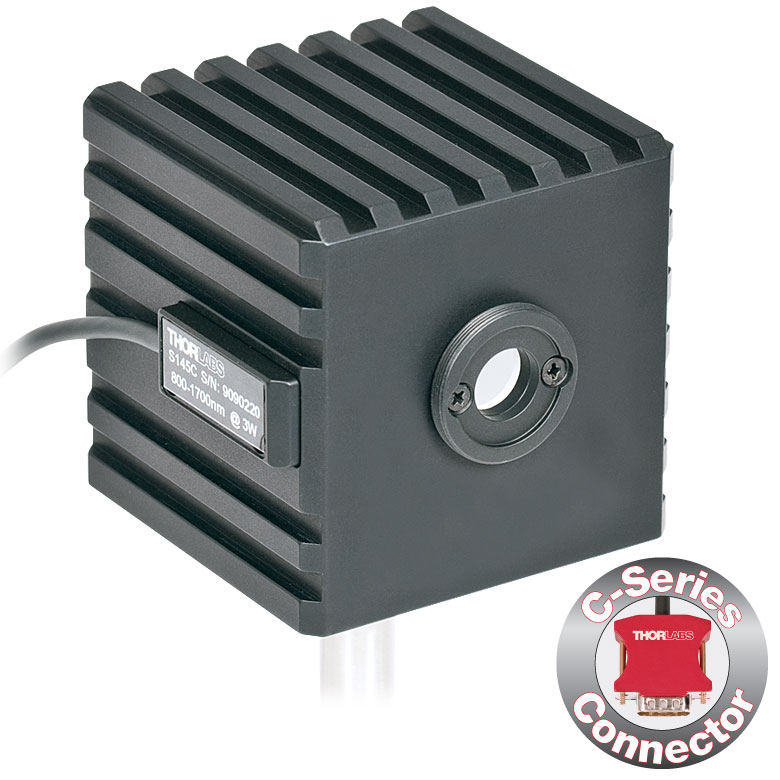
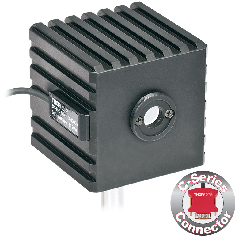
These Integrating Sphere Photodiode Power Sensors are the ideal choice for power measurements independent of beam uniformity, divergence angle, beam shape, or entrance angle, making them excellent for use with fiber sources and off-axis free space sources. They feature enhanced shielding to avoid electromagnetic interference and an over-temperature alert sensor to warn against damage and measurement errors due to overheating of the sensor.
Our integrating spheres are designed for wavelength ranges from the visible through the NIR. Sensor heads for use between 350 and 2500 nm use a single Ø1" or Ø2" sphere made from Zenith® PTFE and feature a black housing to minimize reflected light around the entrance aperture. These sensors use either a silicon photodiode for detection in the 350 - 1100 nm range or an InGaAs photodiode for detection in the 800 - 1700 nm, 900 - 1650 nm, or 1200 - 2500 nm wavelength range.
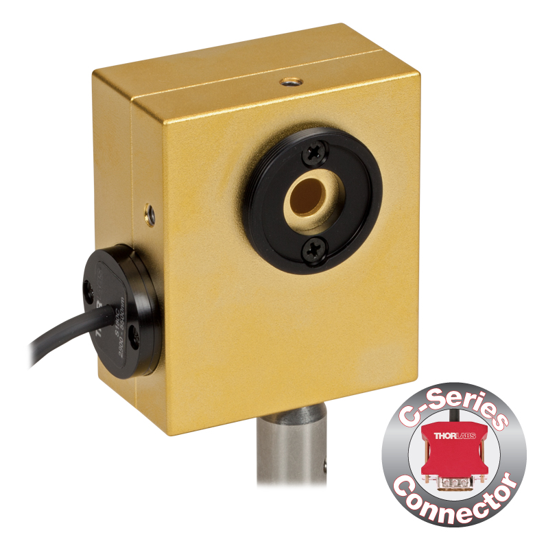
The S180C integrating sphere for 2.9 - 5.5 µm uses two connected, gold-plated Ø20 mm spheres, with an entrance port in the first sphere and a port for the MCT (HgCdTe) detector located in the second sphere. Compared to single-sphere designs, the two-sphere configuration improves device sensitivity by minimizing the internal sphere surface area while still effectively shielding the detector from direct illumination. This design reduces the effect of input angle, divergence, and beam shape on the measurement result by effectively shielding the photodiode without the use of a baffle or other shielding mechanism.
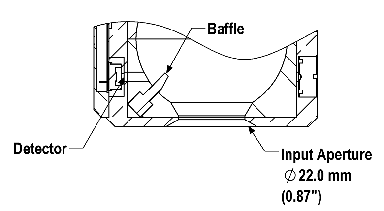
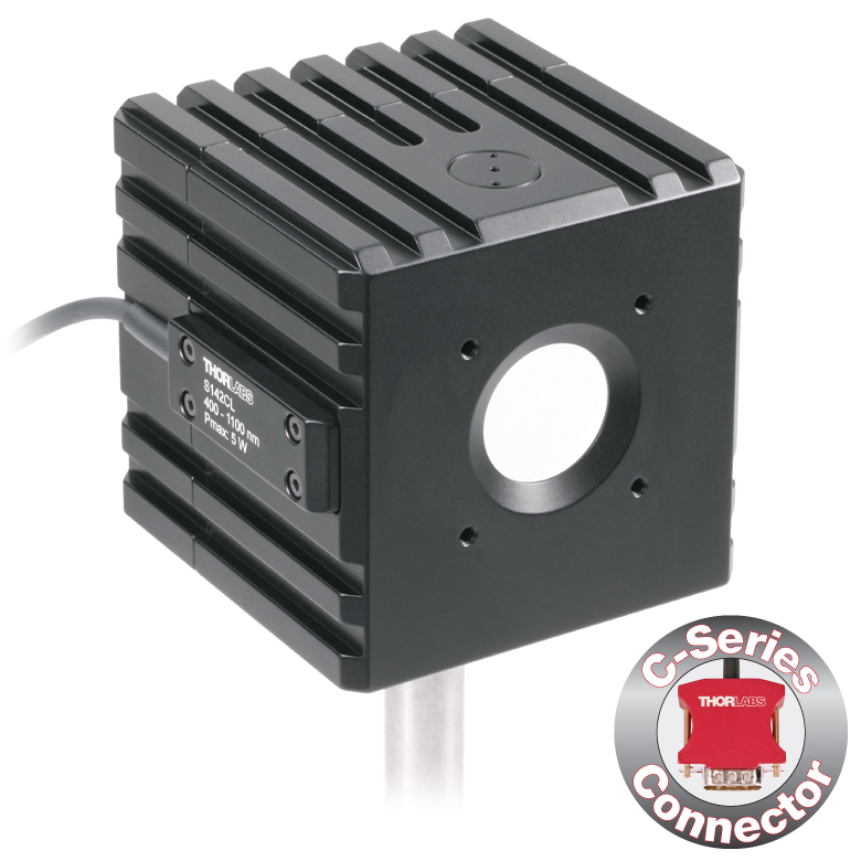
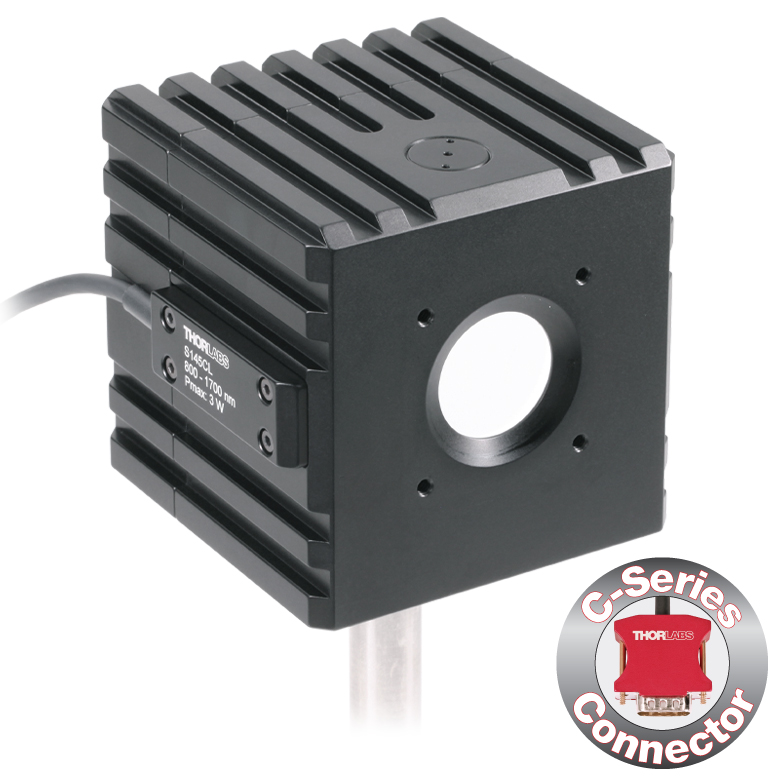
Click to Enlarge
A baffle on the S142CL and S145CL spheres blocks light from directly hitting the detector.
The integrating spheres with Ø5 mm, Ø7 mm, or Ø12 mm apertures feature large active detector areas, and externally SM1-threaded (1.035"-40) adapters for compatibility with the included S120-FC fiber adapter. Because of the large active detector areas of these sensors, the included S120-FC fiber adapter can be used with FC/PC- or FC/APC-terminated fiber. The externally SM1-threaded adapter can be removed using a size 1 screwdriver to place components closer to the window.
The S142CL and S145CL integrating spheres feature a large Ø22 mm input aperture and a baffle within the sphere which prevents direct illumination of the photodiode. The large aperture and baffle enable measurements of large and divergent beams, such as those emitted from LED and VCSEL light sources. The input face of the detectors have four 4-40 threads for mounting 30 mm cage system components. Additionally, insertion of a second or third port in the sensor head is possible on request, please contact Tech Support for details.
Each sensor is shipped with NIST- or PTB-traceable calibration data. The included data will match the calibration certification of the photodiode used to test the individual sensor. NIST- or PTB-traceable data is stored in the sensor connector. Thorlabs offers a recalibration service for these photodiode power sensors, which can be ordered below (see Item # CAL-PD for Si sensors, Item # CAL-IRPD for InGaAs sensors, and Item # CAL-MIRPD for extended InGaAs or MCT sensors).
| Item #a | S140C | S142C | S142CL | S144C | S145C | S145CL | S146C | S148C | S180C | |
|---|---|---|---|---|---|---|---|---|---|---|
| Sensor Image (Click the Image to Enlarge) |
 |
 |
 |
 |
 |
 |
 |
|
 |
|
| Aperture Size | Ø5 mm | Ø12 mm | Ø22 mm | Ø5 mm | Ø12 mm | Ø22 mm | Ø12 mm | Ø5 mm | Ø7 mm | |
| Wavelength Range | 350 - 1100 nm | 400 - 1100 nm | 800 - 1700 nm | 900 - 1650 nm | 1200 - 2500 nm | 2.9 µm - 5.5 µm | ||||
| Power Range | 1 µW - 500 mW | 1 µW - 5 W | 10 µW - 5 W | 1 µW - 500 mW | 1 µW - 3 W | 10 µW - 3 W | 10 µW - 20 W | 1 µW - 1 W | 1 µW - 3 W | |
| Detector Type | Si Photodiode | Si Photodiode with Baffle | InGaAs Photodiode | InGaAs Photodiode with Baffle | InGaAs Photodiode | Extended InGaAs Photodiode | MCT (HgCdTe) Photodiode |
|||
| Linearity | ±0.5% | |||||||||
| Resolutionb | 1 nW | 10 nW | 1 nW | 10 nW | 1 nW | 10 nW | ||||
| Measurement Uncertaintyc,d |
±3% (440 - 980 nm) ±5% (350 - 439 nm) ±7% (981 - 1100 nm) |
±3% (440 - 980 nm) ±5% (400 - 439 nm) ±7% (981 - 1100 nm) |
±5% | |||||||
| Responsivitye (Click for Plot) |
 Raw Data |
 Raw Data |
 Raw Data |
 Raw Data |
 Raw Data |
 Raw Data |
 Raw Data |
 Raw Data |
|
| Integrating Sphere Material (Size) |
Zenith® PTFE (Ø1") |
Zenith® PTFE (Ø2") |
Zenith® PTFE (Ø1") |
Zenith® PTFE (Ø2") |
Zenith® PTFE (Ø1") |
Gold Plating (Two Ø20 mm Spheres) |
||||
| Head Temperature Measurement |
NTC Thermistor 4.7 kΩ | |||||||||
| Housing Dimensions |
Ø45 mm x 30.5 mm | 70 mm x 74 mm x 70 mm | Ø45 mm x 30.5 mm | 70 mm x 74 mm x 70 mm | Ø45 mm x 30.5 mm | 59.0 mm x 50.0 mm x 28.5 |
||||
| Active Detector Area | 3.6 mm x 3.6 mm | Ø2 mm | Ø3 mm | Ø1 mm | Ø1 mm | 1 mm x 1 mm | ||||
| Cable Length | 1.5 m | |||||||||
| Mounting Thread | Separate 8-32 and M4 Taps, Posts Not Included | Universal 8-32 / M4 Thread, Post Not Included | Separate 8-32 and M4 Taps, Posts Not Included | Universal 8-32 / M4 Thread, Post Not Included | Separate 8-32 and M4 Taps, Posts Not Included | Universal |
||||
| Aperture Thread | Included Adapter with SM1 (1.035"-40) External Thread | None | Included Adapter with SM1 (1.035"-40) External Thread | None | Included Adapter with SM1 (1.035"-40) External Thread | |||||
| Compatible Fiber Adapters |
S120-FC (Included) S120-FC2, S120-APC2, S120-APC, S120-SMA, S120-ST, S120-SC, S120-LC, S120-25, and S140-BFA (Not Included) |
None | S120-FC (Included) S120-FC2, S120-APC2, S120-APC, S120-SMA, S120-ST, S120-SC, S120-LC, S120-25, and S140-BFA (Not Included) |
None | S120-FC (Included) S120-FC2, S120-APC2, S120-APC, S120-SMA, S120-ST, S120-SC, S120-LC, S120-25, and S140-BFA (Not Included) |
|||||
| Compatible Consoles | PM400, PM100D, PM100A, and PM5020 | |||||||||
| Compatible Interfaces | PM101, PM101A, PM101R, PM101U, PM103, PM103A, PM103E, PM103U, and PM100USB | |||||||||
Click to Enlarge
PM100D with S150C Sensor and FC Cable
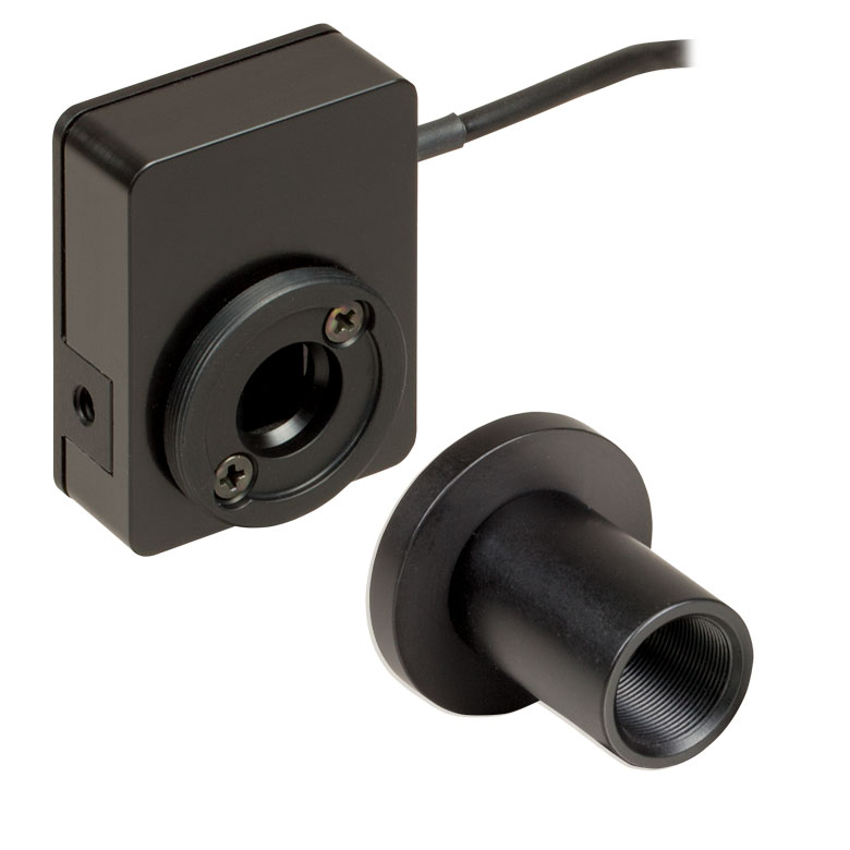
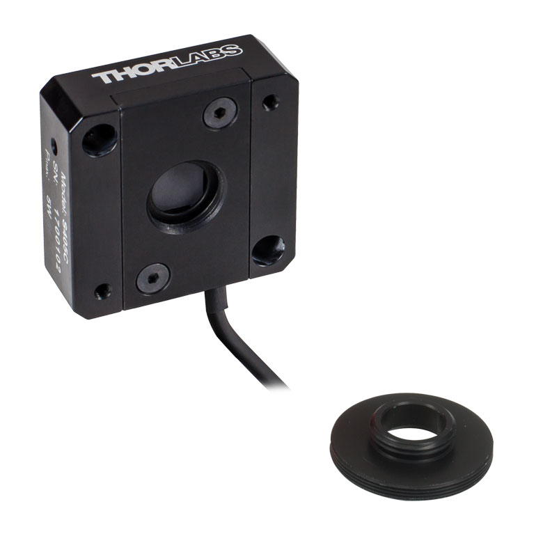
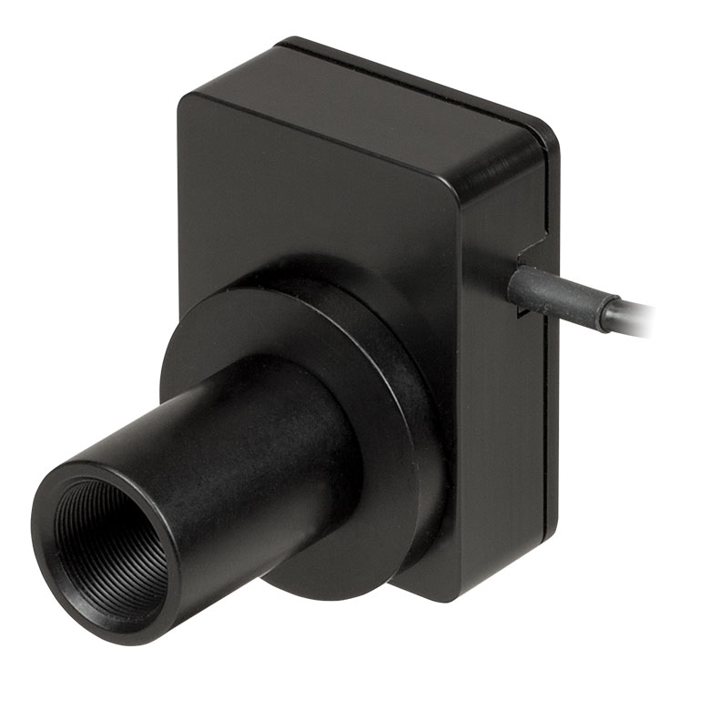
- For Fiber-Based Optical Power Measurements
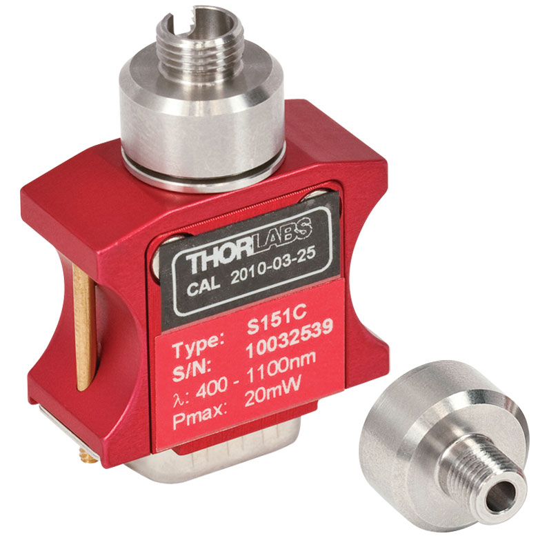
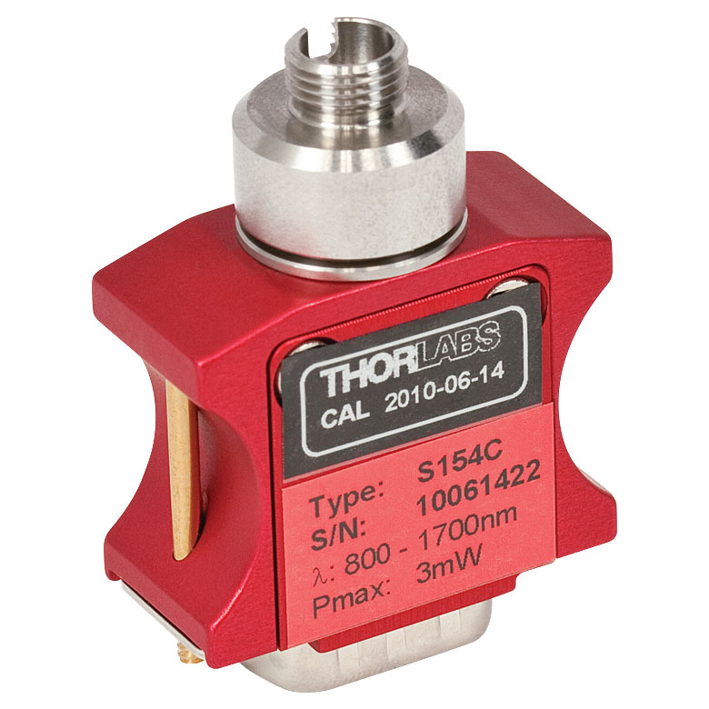
- Compact Sensor Integrated into the Connector
- Integrated Design for use in the Field and Lab
- Includes PM20-FC Fiber Adapter
- S150C and S151C Sensors also Include PM20-SMA Adapters
- Compatible FC/APC, LC/PC, SC/PC, and ST®* Fiber Adapters Also Available (See Table Below)
- See the Full Web Presentation for More Information
The S15xC Compact Fiber Photodiode Power Sensor is designed to take power measurements from a wide variety of fiber coupled sources. The compact sensor, integrated into the power meter connector, features a unique integrated design housing the photodiode sensor, fiber coupling, and NIST-traceable data. Standard FC (and SMA - S150C and S151C) connectors are easily interchanged with a variety of standard fiber connectors.
Thorlabs offers a recalibration service for these photodiode power sensors, which can be ordered below (see Item # CAL-PD for Si sensors and Item # CAL-IRPD for InGaAs sensors).
*ST® is a registered trademark of Lucent Technologies, Inc.
| Item #a | S150C | S151C | S154C | S155C |
|---|---|---|---|---|
| Sensor Image (Click the Image to Enlarge) |
|
|
|
|
| Included Connectors | FCb & SMA | FCb | ||
| Wavelength Range | 350 - 1100 nm | 400 - 1100 nm | 800 - 1700 nm | |
| Power Range | 100 pW to 5 mW (-70 dBm to +7 dBm) |
1 nW to 20 mW (-60 dBm to +13 dBm) |
100 pW to 3 mW (-70 dBm to +5 dBm) |
1 nW to 20 mW (-60 dBm to +13 dBm) |
| Detector Type | Si Photodiode | InGaAs Photodiode | ||
| Linearity | ±0.5% | |||
| Resolutionc | 10 pW (-80 dBm) | 100 pW (-70 dBm) | 10 pW (-80 dBm) | 100 pW (-70 dBm) |
| Measurement Uncertaintyd | ±3% (440 - 980 nm) ±5% (350 - 439 nm) ±7% (981 - 1100 nm) |
±3% (440 - 980 nm) ±5% (400 - 439 nm) ±7% (981 - 1100 nm) |
±5% | |
| Responsivityf (Click for Details) |  Raw Data |
 Raw Data |
 Raw Data |
 Raw Data |
| Coating/Diffuser | N/A | Absorptive ND (Schott NG3) | N/A | |
| Head Temperature Measuremente | NTC Thermistor 3 kΩ | |||
| Aperture Thread | External SM05 (0.535"-40) | |||
| Fiber Adapters | Included: PM20-FC and PM20-SMA Optional: PM20-FC2, PM20-APC2, PM20-APC, PM20-ST, PM20-SC, and PM20-LC |
Included: PM20-FC Optional: PM20-FC2, PM20-APC2, PM20-APC, PM20-SMA, PM20-ST, PM20-SC, and PM20-LC |
||
| Compatible Consoles | PM400, PM100D, PM100A, and PM5020 | |||
| Compatible Interfaces | PM101, PM101A, PM101R, PM101U, PM103, PM103A, PM103E, PM103U, and PM100USB | |||


| Item #a | S401C | S405C |
|---|---|---|
| Sensor Image (Click the Image to Enlarge) |
 |
 |
| Wavelength Range | 190 nm - 20 µm | 190 nm - 20 µm |
| Optical Power Range | 10 µW - 1 W (3 Wb) | 100 µW - 5 W |
| Input Aperture Size | Ø10 mm | Ø10 mm |
| Active Detector Area |
10 mm x 10 mm | 10 mm x 10 mm |
| Max Optical Power Density | 500 W/cm² (Avg.) | 1.5 kW/cm² (Avg.) |
| Detector Type | Thermal Surface Absorber (Thermopile) with Background Compensation |
Thermal Surface Absorber (Thermopile) |
| Linearity | ±0.5% | ±0.5% |
| Resolutionc | 1 µW | 5 µW |
| Measurement Uncertaintyd | ±3% @ 1064 nm ±5% @ 190 nm - 10.6 µm |
±3% @ 1064 nm ±5% @ 250 nm - 17 µm |
| Response Timee | 1.1 s | 1.1 s |
| Cooling | Convection (Passive) | |
| Housing Dimensions (Without Adapter) |
(1.30" x 1.69" x 0.59") |
40.6 mm x 40.6 mm x 16.0 mm (1.60" x 1.60" x 0.63") |
| Temperature Sensor (In Sensor Head) |
NTC Thermistor | NTC Thermistor |
| Cable Length | 1.5 m | |
| Post Mounting | Universal 8-32 / M4 Taps (Post Not Included) |
Universal 8-32 / M4 Taps (Post Not Included) |
| 30 mm Cage Mounting | - | Two 4-40 Tapped Holes & Two Ø6 mm Through Holes |
| Aperture Threads | - | Internal SM05 |
| Accessories | Externally SM1-Threaded Adapter Light Shield with Internal SM05 Threading |
Externally SM1-Threaded Adapter |
| Compatible Consoles | PM400, PM100D, PM100A, and PM5020 | |
| Compatible Interfaces | PM101, PM101A, PM101R, PM101U, PM102, PM102A, PM102U, and PM100USB | |
- High Resolution of 1 μW or 5 μW
- S401C and S405C Have Thermistors Used to Monitor Temperature of Sensor Head
- S401C: Background Compensation for Low-Drift Measurements
- S405C: Accommodates Average Optical Power Densities up to 1.5 kW/cm²
- See the Full Web Presentation for More Information
Click to Enlarge
S401C Thermal Sensor with Included Light Shield
Thorlabs offers two broadband thermal power sensors designed to measure low optical power sources with high resolution. Each thermal sensor's broadband coating has a flat spectral response over a wide wavelength range, as shown in the plot below.
An aperture size of Ø10 mm allows for easy alignment and measurement of large-spot-size laser sources. For easy integration with Thorlabs' lens tube systems and SM1-threaded (1.035"-40) fiber adapters, each sensor has either external SM1 threading or includes an externally SM1-threaded adapter.
The S401C uses active thermal background compensation to provide low-drift power measurements. This is implemented through the use of two similar sensor circuits. One sensor circuit is the type all thermal power sensors share: it measures heat flow from light absorber to heat sink. The other sensor circuit monitors the ambient temperature. It is located within the housing and measures heat flow from heat sink towards the absorber. The measurements of the two sensor circuits are subtracted, which minimizes the effect of thermal drift on the laser power measurement. (For information about how the external thermal disturbances can affect thermal power sensor readings, see the Operation tab.) The broadband coating used on this thermal sensor offers high absorption at wavelengths between 0.19 and 20 µm (shown in the graph), which makes the sensor ideal for use with aligning and measuring Mid-IR Quantum Cascade Lasers (QCLs). The included, internally SM05-threaded (0.535"-40) light shield is shown in the photo to the right.
The S405C has internal SM05 (0.535"-40) threading that is directly compatible with SM05 lens tubes, and it can also connect directly to Thorlabs' 30 mm Cage Systems.
Thorlabs offers a recalibration service for these sensors, which can be ordered below (see Item # CAL-THPY).
Click to Enlarge
The S405 shares the same absorption curve with the S415C, S425C, and S245C-L. (All are sold below.)
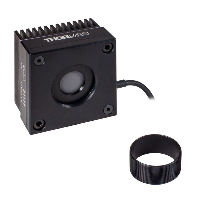
| Item #a | S415C | S425C |
|---|---|---|
| Sensor Image (Click Image to Enlarge) |
 |
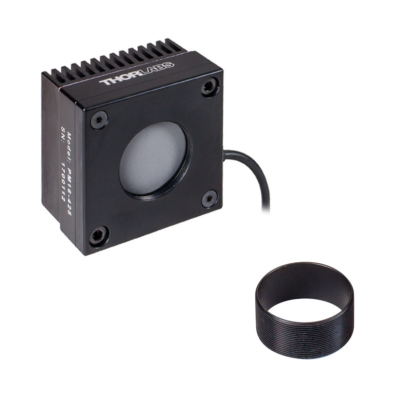 |
| Wavelength Range | 190 nm - 20 µm | 190 nm - 20 µm |
| Optical Power Range | 2 mW - 10 W (20 Wb) | 2 mW - 10 W (20 Wb) |
| Input Aperture Size | Ø15 mm | Ø25.4 mm |
| Active Detector Area |
Ø15 mm | Ø27 mm |
| Max Optical Power Density |
1.5 kW/cm² (Avg.) | 1.5 kW/cm² (Avg.) |
| Detector Type | Thermal Surface Absorber (Thermopile) | |
| Linearity | ±0.5% | ±0.5% |
| Resolutionc | 100 µW | 100 µW |
| Measurement Uncertaintyd |
±3% @ 1064 nm ±5% @ 250 nm - 17 µm |
±3% @ 1064 nm ±5% @ 250 nm - 17 µm |
| Response Timee | 0.6 s | 0.6 s |
| Cooling | Convection (Passive) | |
| Housing Dimensions (Without Adapter) |
(2.00" x 2.00" x 1.38") |
(2.00" x 2.00" x 1.38") |
| Temperature Sensor (In Sensor Head) |
NTC Thermistor | |
| Cable Length | 1.5 m | |
| Post Mounting | Universal 8-32 / M4 Taps (Post Not Included) |
Universal 8-32 / M4 Taps (Post Not Included) |
| 30 mm Cage Mounting | - | - |
| Aperture Threads | Internal SM1 | Internal SM1 |
| Removable Heatsink | Yes | Yes |
| Accessories | Externally SM1-Threaded Adapter | Externally SM1-Threaded Adapter |
| Compatible Consoles | PM400, PM100D, PM100A, and PM5020 | |
| Compatible Interfaces | PM101, PM101A, PM101R, PM101U, PM102, PM102A, PM102U, and PM100USB | |
- 100 µW Optical Power Resolution
- Thermistors Used to Monitor Temperature of Sensor Head
- Removable Heat Sinks Included
- See the Full Web Presentation for More Information
These thermal power sensors are designed for general broadband power measurements of low and medium power light sources. All include an externally SM1-threaded (1.035"-40) adapter, with threading concentric with the input aperture. The adapters are useful for mounting Ø1" Lens Tubes and Fiber Adapters (available below). The apertures of the S415C and S425C have internal SM1 threading.
These sensors operate with fast (<0.6 s) natural response times, and their removable heat sinks provide a high degree of flexibility to those interested in integrating them into custom setups or replacing the included heat sink with one that is water or fan cooled. If replacing the heat sink, please note that the replacement must provide heat dissipation adequate for the application.
Thorlabs offers a recalibration service for these sensors, which can be ordered below (see Item # CAL-THPY).

Click to Enlarge
The absorption curves of each of the thermal power sensors designed for use with low and medium power optical sources.
Click to Enlarge
The absorption curves of each of the thermal power sensors designed for use with low and medium power optical sources.
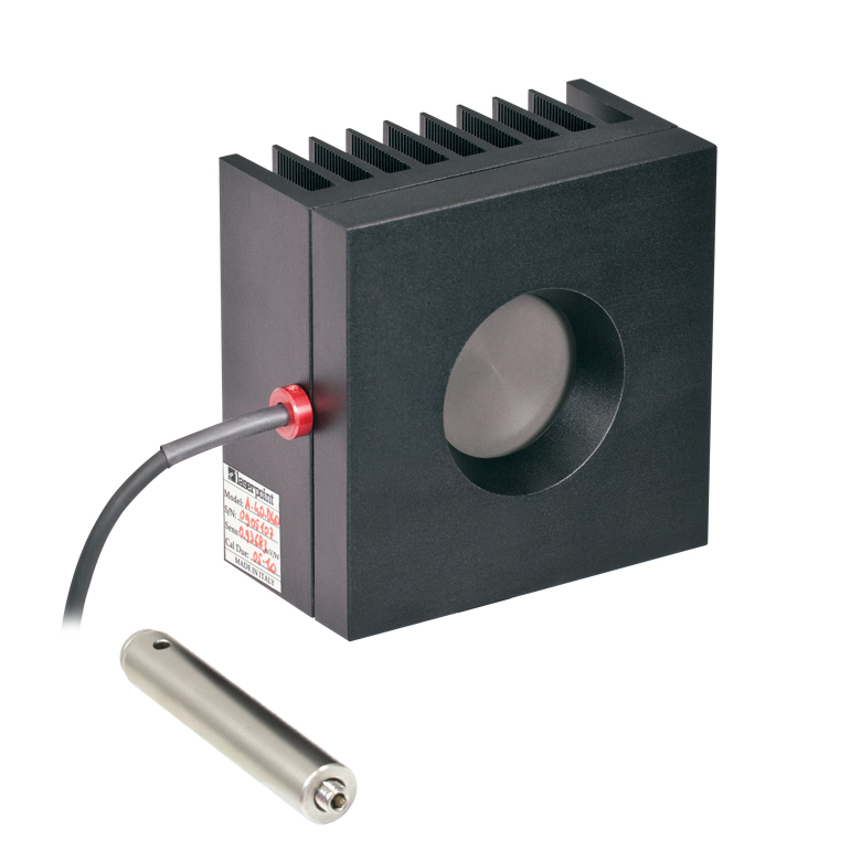
- Thermistors Used to Monitor Temperature of Sensor Head
- S322C Has 4-40 Taps for Use with Our 30 mm Cage Systems
- S350C Has Ø40 mm Aperture Well Suited to Excimer and Other Lasers with Large Spot Sizes
- S425C-L Features Removable Heat Sink
- S322C is Fan Cooled with an Optical Power Range up to 200 W
- See the Full Web Presentation for More Information
These thermal power sensors are designed for general broadband power measurements of low and medium power light sources. With the exception of the S350C, all include an adapter with external SM1 (1.035"-40) threading concentric with the input aperture. This allows the sensors to be integrated into existing Ø1" lens tube systems in addition to being compatible with fiber adapters (available below). The aperture of the S425C-L has internal SM1 threading.
The S425C-L operates with a fast (<0.6 s) natural response time and has a removable heat sink, which provides a high degree of flexibility to those interested in integrating them into custom setups or replacing the included heat sink with one that is water or fan cooled. If replacing the heat sink, please note that the replacement must provide heat dissipation adequate for the application.
Thorlabs offers a recalibration service for these sensors, which can be ordered below (see Item # CAL-THPY).
| Item #a | S350C | S425C-L | S322C |
|---|---|---|---|
| Sensor Image (Click Image to Enlarge) |
 |
 |
 |
| Wavelength Range | 190 nm- 1.1 µm, 10.6 µm | 190 nm - 20 µm | 250 nm - 11 µm |
| Optical Power Range | 10 mW - 40 W (60 Wb) | 2 mW - 50 W (75 Wb) | 100 mW - 200 W (250 Wb) |
| Input Aperture Size | Ø40 mm | Ø25.4 mm | Ø25 mm |
| Active Detector Area |
Ø40 mm | Ø27 mm | Ø25 mm |
| Max Optical Power Density | 2 kW/cm² (Avg.) | 1.5 kW/cm² (Avg.) | 4 kW/cm² (Avg., CO2) |
| Detector Type | Thermal Surface Absorber (Thermopile) | ||
| Linearity | ±1% | ±0.5% | ±1% |
| Resolutionc | 1 mW | 100 µW | 5 mW |
| Measurement Uncertaintyd | ±3% @ 1064 nm ±5% @ 190 nm - 1100 nm, 10.6 µm |
±3% @ 1064 nm ±5% @ 250 nm - 17 µm |
±3% @ 1064 nm ±5% @ 266 nm - 1064 nm |
| Response Timee | 9 s (1 s from 0 to 90%) |
0.6 s | 5 s (1 s from 0 to 90%) |
| Cooling | Convection (Passive) | Forced Air with Fanf | |
| Housing Dimensions (Without Adapter, if Applicable) |
100 mm x 100 mm x 54.2 mm (3.94" x 3.94" x 2.13") |
100.0 mm x 100.0 mm x 58.0 mm (3.94" x 3.94" x 2.28") |
100 mm x 100 mm x 86.7 mm (3.94" x 3.94" x 3.41") |
| Temperature Sensor (In Sensor Head) |
NTC Thermistor | ||
| Cable Length | 1.5 m | ||
| Post Mounting | M6 Threaded Taps, Includes Ø1/2" Post, 75 mm Long |
Universal 8-32 / M4 Taps (Post Not Included) |
M6 Threaded Taps, Includes Ø1/2" Post, 75 mm Long |
| 30 mm Cage Mounting | - | - | Four 4-40 Tapped Holes |
| Aperture Threads | - | Internal SM1 | - |
| Removable Heatsink | - | Yes | - |
| Accessories | - | Externally SM1-Threaded Adapter | Externally SM1-Threaded Adapter |
| Compatible Consoles | PM400, PM100D, PM100A, and PM5020 | ||
| Compatible Interfaces | PM101, PM101A, PM101R, PM101U, PM102, PM102A, PM102U, and PM100USB | ||
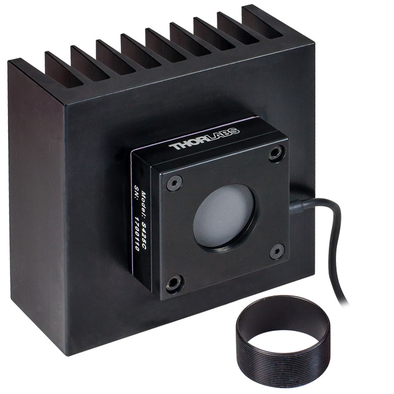
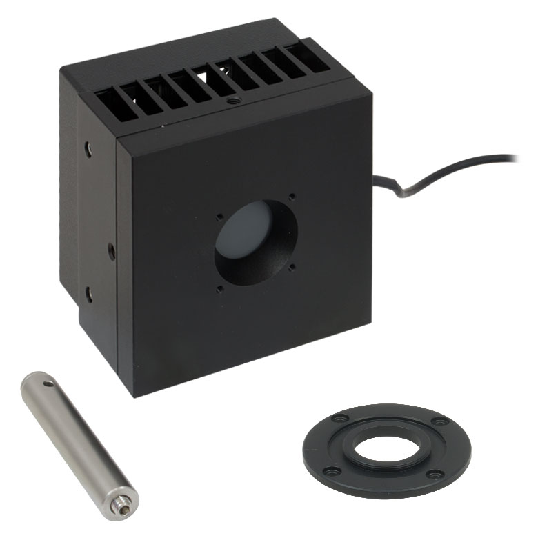
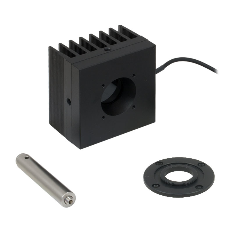
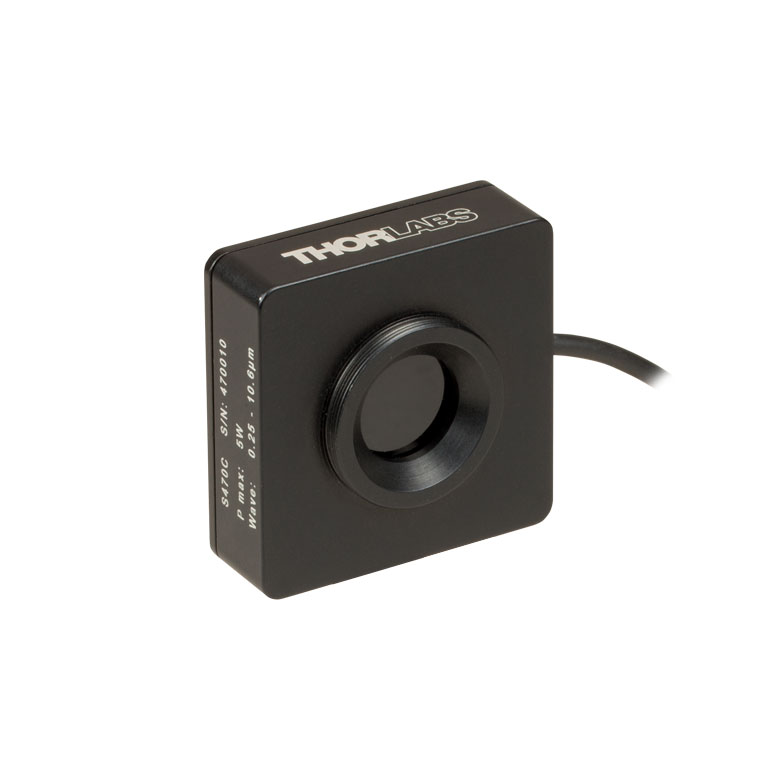
| Item #a | S370C | S470C |
|---|---|---|
| Sensor Image (Click the Image to Enlarge) |
 |
 |
| Wavelength Range | 400 nm - 5.2 µm | 250 nm - 10.6 µm |
| Optical Power Range | 10 mW - 10 W (15 Wb) | 100 µW - 5 W (Pulsed and CW) |
| Input Aperture Size | Ø25 mm | Ø15 mm |
| Active Detector Area |
Ø25 mm | Ø16 mm |
| Max Optical Power Density | 35 W/cm² (Avg.); 100 GW/cm² (Peak) | |
| Detector Type | Thermal Volume Absorber (Thermopile) | |
| Linearity | ±1% | ±0.5% |
| Resolutionc | 250 µW | 10 µW |
| Measurement Uncertaintyd | ±3% @ 1064 nm ±5% @ 400 nm - 1064 nm |
±3% @ 1064 nm ±5% @ 250 nm - 10.6 µm |
| Response Timee | 45 s (3 s from 0 to 90%) |
6.5 s (<2 s from 0 to 90%) |
| Cooling | Convection (Passive) | |
| Housing Dimensions (Without Adapter, if Applicable) |
(2.95" x 2.95" x 2.02") |
(1.77" x 1.77" x 0.71") |
| Temperature Sensor (In Sensor Head) |
N/A | N/A |
| Cable Length | 1.5 m | |
| Post Mounting | M6 Threaded Taps, Includes Ø1/2" Post, 75 mm Long |
Universal 8-32 / M4 Tap (Post Not Included) |
| 30 mm Cage Mounting | Four 4-40 Tapped Holes | - |
| Aperture Threads | - | External SM1 |
| Accessories | - | |
| Compatible Consoles | PM400, PM100D, PM100A, and PM5020 | |
| Compatible Interfaces | PM101, PM101A, PM101R, PM101U, PM102, PM102A, PM102U, and PM100USB | |
- Designed for Optical Power Measurements of Nd:YAG Lasers
- Ideal for Applications with High Peak Pulse Powers
- S370C: Ø25 mm Aperture for Large-Spot-Size Beams
- S470C: High-Sensitivity for High-Peak-Power Pulses with Low Average Power
- See the Full Web Presentation for More Information
The S370C and S470C Thermal Sensors are designed to measure short and highly energetic laser pulses. All of these units are post-mountable for free-space applications and feature NIST-traceable data stored in the sensor connector.
These thermal power sensors are unique in that they have thermal volume absorbers, where our other thermal power sensors have thermal surface absorbers. The volume absorber consists of a Schott glass filter. Incident pulses are absorbed and the heat is distributed throughout the volume. In this way, pulses that would have damaged the absorption coating of a thermal surface absorber are safely measured by these thermal volume absorbers.
The S370C features a large Ø25 mm aperture ideal for large-spot-size beams, and it is compatible with average powers from 10 mW to 10 W (CW).
In comparison, the S470C is faster, as the glass absorber volume is reduced and other design parameters have been optimized for speed. This results in a different optical power range, with the ability to measure powers down to 100 µW. The Ø15 mm aperture is of the S470C is smaller, and it has a lower max average power of 5 W. Its 10 µW resolution is better than the 250 µW resolution of the S370C.
Thorlabs offers a recalibration service for these sensors, which can be ordered below (see Item # CAL-THPY).
Click to Enlarge
This absorption curve is shown over a broader wavelength range than the sensors' operating ranges. See the table for the operating wavelength range of each sensor.
| Calibration Service Item # | Compatible Sensors |
|---|---|
| CAL-UVPD | S120VC |
| CAL-PD | S116C, S120C, S121C, S170C, S171C, S140C, S142C, S142CL, S150C, S151C, PM16-120, PM16 |
| CAL-UVPD2 | S130VC |
| CAL-PD2 | S130C, PM16-130, PM160 |
| CAL-IRPD | S122C, S144C, S145C, S145CL, S146C, S154C, S155C, PM16-122, PM16-144 |
| CAL-IRPD2 | S132C |
| CAL-MIRPD | S148C, S180C |
Thorlabs offers recalibration services for our photodiode optical power sensors. To ensure accurate measurements, we recommend recalibrating the sensors annually. Recalibration of a single-channel power and/or energy meter console or interface is included with the recalibration of a sensor at no additional cost. If you wish to calibrate one or more sensors with a dual-channel console, each sensor and console calibration service will need to be purchased individually. For more details on these recalibration services, please click the Documents (![]() ) icons below.
) icons below.
Refer to the table to the right for the appropriate calibration service Item # that corresponds to your power sensor.
Requesting a Calibration
Thorlabs provides two options for requesting a calibration:
- Complete the Returns Material Authorization (RMA) form. When completing the RMA form, please enter your name, contact information, the Part #, and the Serial # of each item being returned for calibration; in the Reason for Return field, select "I would like an item to be calibrated." All other fields are optional. Once the form has been submitted, a member of our RMA team will reach out to provide an RMA Number, return instructions, and to verify billing and payment information.
- Select the appropriate sensor calibration Item # below, enter the Part # and Serial # of the sensor that requires recalibration, and then Add to Cart. If you would like a console calibrated with your sensor, repeat this process for Item # CAL-PM1 or CAL-PM2 below, entering the console Item # and Serial #. A member of our RMA team will reach out to coordinate the return of the item(s) for calibration. Note that each console calibration Item # represents the cost of calibrating a console alone; if requesting a single-channel console calibration with a sensor calibration, the appropriate discount will be applied when your request is processed. Should you have other items in your cart, note that the calibration request will be split off from your order for RMA processing.
Please Note: To ensure your item being returned for calibration is routed appropriately once it arrives at our facility, please do not ship it prior to being provided an RMA Number and return instructions by a member of our team.
| Sensor Type | Sensor Item #s |
|---|---|
| Thermal Power | S175C, S302Ca, S305Ca, S310Ca, S314Ca,S322C, S350C, S370C, S401C, S405C, S415C, S425C, S425C-L, S470C, PM160T, PM160T-HP, PM16-401, PM16-405 |
| Pyroelectric Energy | ES111C, ES120C, ES145C, ES220C, ES245C, ES308C, ES312C, ES408C, ES412C |
Thorlabs offers recalibration services for our Thermal Power and Pyroelectric Energy Sensors. To ensure accurate measurements, we recommend recalibrating the sensors annually. Recalibration of a single-channel power and/or energy meter console or interface is included with the recalibration of a sensor at no additional cost. If you wish to calibrate one or more sensors with a dual-channel console, each sensor and console calibration service will need to be purchased individually.
Please note that the CAL-THPY recalibration service cannot be used for our Thermal Position & Power Sensors; recalibration for these sensors can be requested by contacting Tech Support. The table to the upper right lists the sensors for which the CAL-THPY recalibration service is available.
Requesting a Calibration
Thorlabs provides two options for requesting a calibration:
- Complete the Returns Material Authorization (RMA) form. When completing the RMA form, please enter your name, contact information, the Part #s, and the Serial #s of all sensors or consoles being returned for calibration; in the Reason for Return field, select "I would like an item to be calibrated." All other fields are optional. Once the form has been submitted, a member of our RMA team will reach out to provide an RMA Number, return instructions, and to verify billing and payment information.
- Enter the Part # and Serial # of the item that requires recalibration below and then Add to Cart. If you would like a console calibrated with your sensor, repeat this process for Item # CAL-PM1 or CAL-PM2 below, entering the console Item # and Serial #. A member of our RMA team will reach out to coordinate the return of the item(s) for calibration. Note that each console calibration Item # represents the cost of calibrating a console alone; if requesting a single-channel console calibration with a sensor calibration, the appropriate discount will be applied when your request is processed. Should you have other items in your cart, note that the calibration request will be split off from your order for RMA processing.
Please Note: To ensure your item being returned for calibration is routed appropriately once it arrives at our facility, please do not ship it prior to being provided an RMA Number and return instructions by a member of our team. Pyroelectric energy sensors returned for recalibration or servicing must include the separate BNC to DB9 adapter, which contains the sensor EEPROM.
| Calibration Service Item # | Compatible Consoles & Interfaces |
|---|---|
| Single-Channel | |
| CAL-PM1 | PM100D, PM100A, PM400, PM100USB, PM101 Series, PM102 Series, PM103 Series |
| Dual-Channel | |
| CAL-PM2 | PM5020, Previous-Generation PM320E |
These recalibration services are for the power and/or energy meter electronics of our consoles and interfaces. To ensure accurate measurements, we recommend recalibrating annually. Recalibration of a single-channel console or interface is included with these sensor recalibration services at no additional cost. If you wish to calibrate one or more sensors with a dual-channel console, each sensor and console calibration service will need to be purchased individually. For more details on these recalibration services, please click the Documents (![]() ) icons below.
) icons below.
The table to the upper right lists the power and/or energy meter consoles and interfaces that can be calibrated using the CAL-PM1 and CAL-PM2 recalibration services.
Requesting a Calibration
Thorlabs provides two options for requesting a calibration:
- Complete the Returns Material Authorization (RMA) form. When completing the RMA form, please enter your name, contact information, the Part #, and the Serial # of each item being returned for calibration; in the Reason for Return field, select "I would like an item to be calibrated." All other fields are optional. Once the form has been submitted, a member of our RMA team will reach out to provide an RMA Number, return instructions, and to verify billing and payment information.
- Select the appropriate Item # below, enter the Part # and Serial # of the item that requires recalibration, and then Add to Cart. If you would like to calibrate one or more sensors with your console, repeat this process for the appropriate sensor recalibration service above, entering the console Item # and Serial #. A member of our RMA team will reach out to coordinate return of the item(s) for calibration. Note that each console calibration Item # represents the cost of calibrating a console alone; if requesting a single-channel console calibration with a sensor calibration, the appropriate discount will be applied when your request is processed. Should you have other items in your cart, note that the calibration request will be split off from your order for RMA processing.
Please Note: To ensure your item being returned for calibration is routed appropriately once it arrives at our facility, please do not ship it prior to being provided an RMA Number and return instructions by a member of our team.