 Products Home / Incoherent Sources / Light Emitting Diodes (LEDs) / Cage-Compatible Diffuse Backlight LED
Cage-Compatible Diffuse Backlight LED
- LED Backlight with Ø25 mm Diffused Aperture Size
- Integrates with 30 mm Cage Systems
- Compatible with Thorlabs' LED Drivers
Application Idea
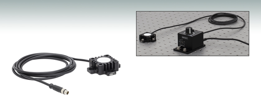
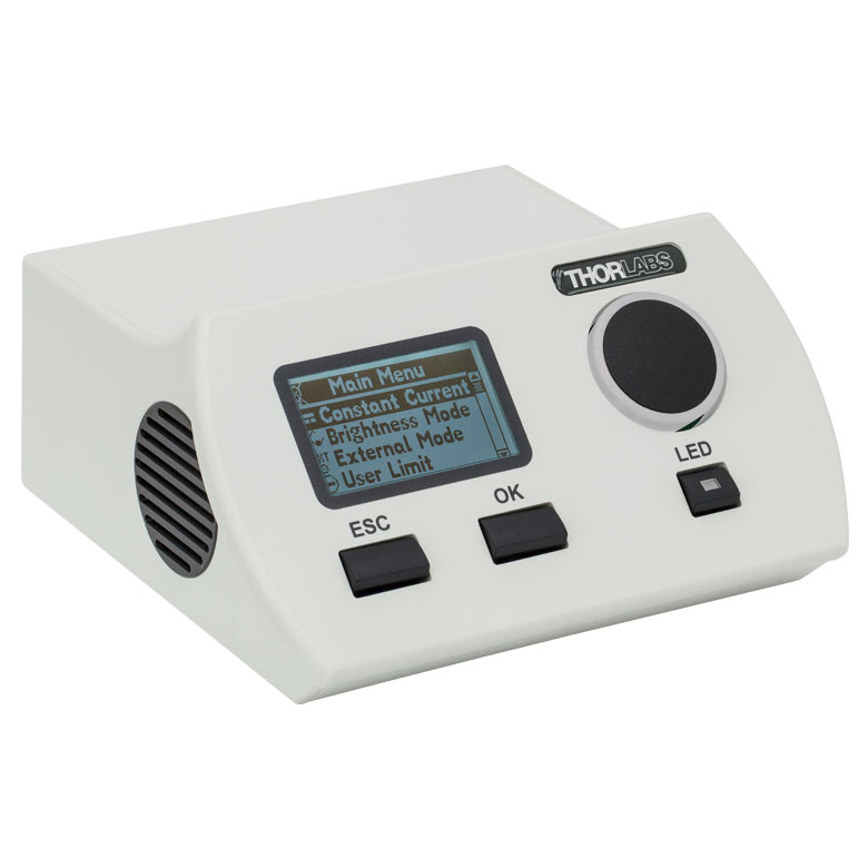
The LEDD1B T-Cube LED Driver can be used to drive the LEDBW1 Backlight LED.
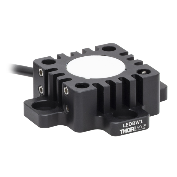
LEDBW1
Ø25 mm Diffuse Backlight LED, Cold White


Please Wait
| Item # | LEDBW1 | ||
|---|---|---|---|
| Min | Typical | Max | |
| LED Power Outputa,b | 251 mW | 358 mW | - |
| Forward Voltagea,b | - | 3.9 V | - |
| Maximum Irradiancea,b,c | - | 6.3 µW/mm2 | - |
| General Specifications | |||
| Color | Cold White | ||
| Correlated Color Temperatured | 6500 K | ||
| Diffused Aperture Sizee | Ø25 mm | ||
| Maximum Current (CW)a | 2000 mA | ||
| Electrical Powera | 7800 mW | ||
| Typical Lifetimea | 100 000 h | ||
| Operating Temperaturef | 0 to 40 °C | ||
| Storage Temperature | -40 to 70 °C | ||
| Risk Groupg | RG0 - Exempt | ||
| Output Spectrumd (Click to View) |
 Click Here for Raw Data |
||

Click to Enlarge
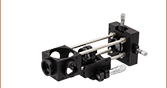
The CFS1(/M) Sliding Filter Mount can be used with the LEDBW1 Cage-Compatible LED Backlight to filter specific wavelength ranges of the output.
Features
- High-Power Diffuse Illuminator Ideal for Machine Vision Applications
- Ø25 mm Diffused Aperture Size
- 100 000 Hour Lifetime
- Compatible with Our 30 mm Cage System
- Low-Profile Housing
- Integrated Memory (EEPROM) Stores LED Operating Parameters
- Integrated M8 Connector for use with Thorlabs' LED Drivers
Thorlabs' Cage-Compatible Diffuse Backlight LED is a high-power, cold white LED that provides stable, uniform illumination. By integrating a Ø25 mm diffused window, this LED backlight produces a flatter field of illumination as compared to a point source, making it ideal for machine vision applications.
Constructed from anodized aluminum, this LED housing features four through holes that are compatible with our Ø6 mm ER cage rods. This allows for integration with our 30 mm cage systems and DIY Cerna components, such as the CSA1001 Fixed Arm. Each cage rod through hole is accompanied by two side-located locking setscrews, which can be secured using a 5/64" (2.0 mm) hex key or balldriver.
To ensure proper operation and to maximize operating lifetime, this LED backlight must be mounted onto an appropriate heat sink; the housing includes four counterbored slots that accept 1/4" (M6) cap screws (not included) for compatibility with both imperial and metric hole patterns. For convenient connection to the drivers listed on the LED Drivers tab, this LED backlight has a connection cable with an M8 connector; see the Pin Diagrams tab for the M8 connector pin information.
This LED backlight features an EEPROM chip which stores information about the LED (e.g., current limit, forward voltage). When controlled by a Thorlabs DC2200, DC4100, DC4104, or UPLED LED driver, the data can be used to implement smart safety features.
White Light LEDs
This illuminator is a cold white LED featuring a broad spectrum that spans several hundred nanometers; see the table to the right for a typical output spectrum. It has a correlated color temperature of 6500 K, which indicates that the color appearance is similar to a black body radiator at the same temperature. In general, a cold white LED has a stronger blue component to the spectrum than a warm white or neutral white LED. Compared to warm white LEDs, cold white LEDs are more suitable for fluorescence microscopy applications or use with cameras with white balancing due to their higher intensity at most wavelengths. To discuss LED backlights with other correlated color temperatures or nominal wavelengths, please contact Tech Support.
Driver Options
Thorlabs offers five drivers compatible with this LED backlight: DC2200, UPLED, LEDD1B, DC4100, and DC4104 (the latter two require the DC4100-HUB). See the LED Drivers tab for compatibility information and a list of specifications. We recommend using the DC2200 for applications that require the full power of the LED; the LEDBW1 LED has a higher maximum current rating than the the UPLED, LEDD1B, DC4100 and DC4101 drivers are able to provide, which will limit the achievable LED output power when used with these drivers. In addition, the DC2200, DC4100, DC4104, and UPLED drivers are capable of reading the current limit from the EEPROM chip of the connected LED and automatically adjusting the maximum current setting to protect the LED.
Please note that this LED backlight is not intended for use in household illumination applications.
Thorlabs also offers a range of unmounted, mounted, collimated, and fiber-coupled LEDs that are designed for a variety of applications, including microscopy, illumination, and measurements. For questions on choosing an appropriate LED and to discuss mounting requirements, please contact Tech Support.

| Pin | Specification | Color |
|---|---|---|
| 1 | LED Anode | Brown |
| 2 | LED Cathode | White |
| 3 | EEPROM GND | Black |
| 4 | EEPROM IO | Blue |
Pin Connection - Male
The diagram to the right shows the male connector of the LEDBW1 Backlight. It is a standard M8 x 1 sensor circular connector. Pins 1 and 2 are the connection to the LED. Pin 3 and 4 are used for the internal EEPROM. If using an LED driver that was not purchased from Thorlabs, be careful that the appropriate connections are made to Pin 1 and Pin 2 and that you do not attempt to drive the LED through the EEPROM pins.
To fully support the max optical power of the LED you intend to drive, ensure that the max voltage and max current of the driver are equal to or greater than those of the LED.
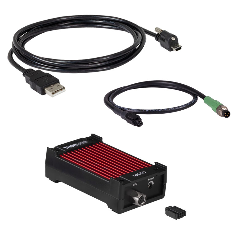
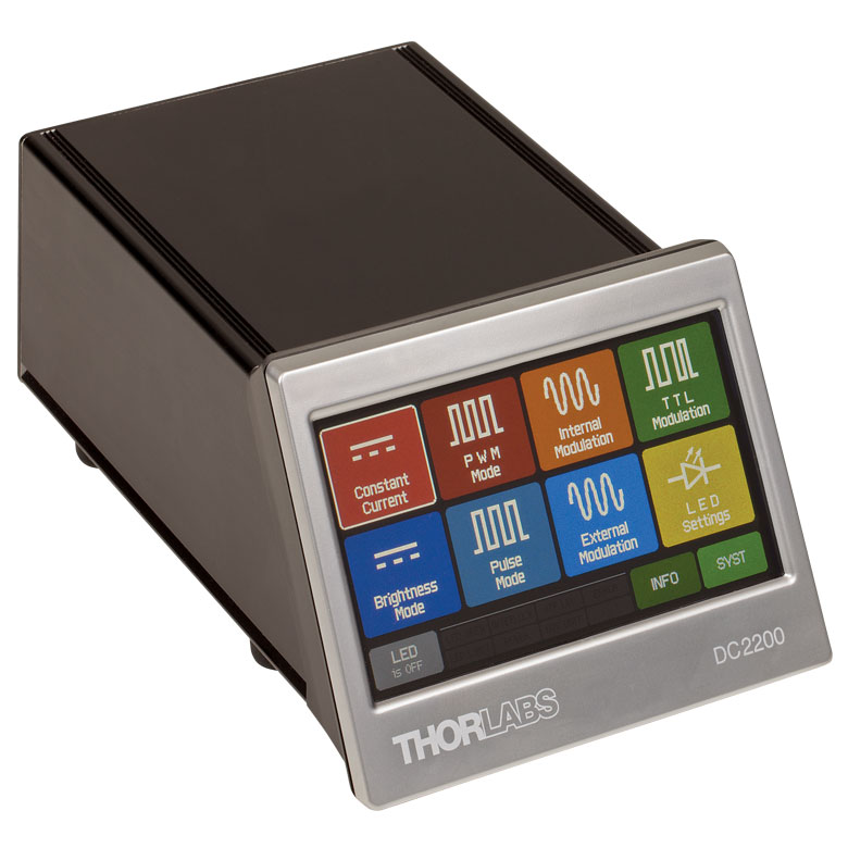
| Compatible Drivers | LEDD1B | UPLEDa | DC2200a | DC4100a,b | DC4104a,b |
|---|---|---|---|---|---|
| Click Photos to Enlarge |  |
 |
 |
 |
 |
| LED Driver Current Output (Max)c | 1.2 A | 1.2 A | LED1 Terminal: 10.0 A LED2 Terminal: 2.0 Ad |
1.0 A per Channel | 1.0 A per Channel |
| LED Driver Forward Voltage (Max)e | 12 V | 8 V | 50 V | 5 V | 5 V |
| Modulation Frequency Using External Input (Max) | 5 kHz | - | 250 kHzf,g | 100 kHzg (Simultaneous Across all Channels) |
100 kHzg (Independently Controlled Channels) |
| External Control Interface(s) | Analog (BNC) | USB 2.0 | USB 2.0 and Analog (BNC) | USB 2.0 and Analog (BNC) | USB 2.0 and Analog (8-Pin) |
| Main Driver Features | Very Compact Footprint 60 mm x 73 mm x 104 mm (W x H x D) |
USB-Controlled | Touchscreen Interface with Internal and External Options for Pulsed and Modulated LED Operation | 4 Channelsb | 4 Channelsb |
| EEPROM Compatible: Reads Out LED Data for LED Settings | - | ||||
| LCD Display | - | - |
| Posted Comments: | |
| No Comments Posted |
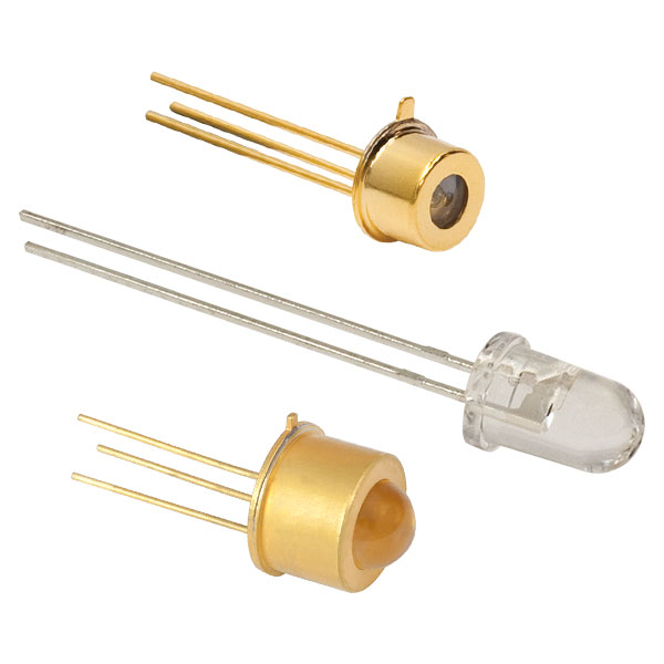
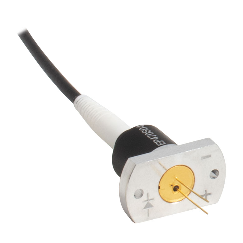
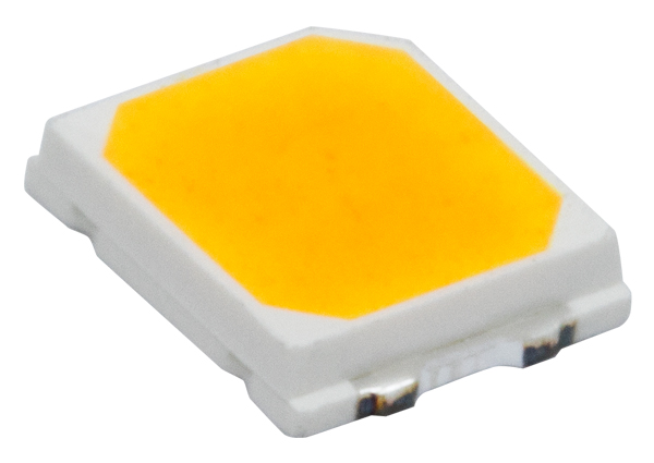
This tab includes all LEDs sold by Thorlabs. Click on More [+] to view all available wavelengths for each type of LED pictured below.
| Light Emitting Diode (LED) Selection Guide | ||||||
|---|---|---|---|---|---|---|
| Click Photo to Enlarge (Representative; Not to Scale) |
 |
 |
 |
 |
 |
 |
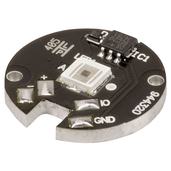
| Type | Unmounted LEDs | Pigtailed LEDs | LEDs in SMT Packages |
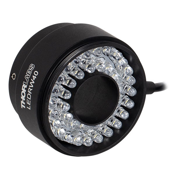
LED Arrays | LED Ring Light | Cage-Compatible Diffuse Backlight LED |
| Light Emitting Diode (LED) Selection Guide | ||||||
|---|---|---|---|---|---|---|
| Click Photo to Enlarge (Representative; Not to Scale) |
 |
 |
 |
 |
 |
 |
| Type | PCB- Mounted LEDs |
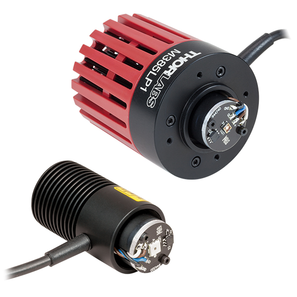
Heatsink- Mounted LEDs |
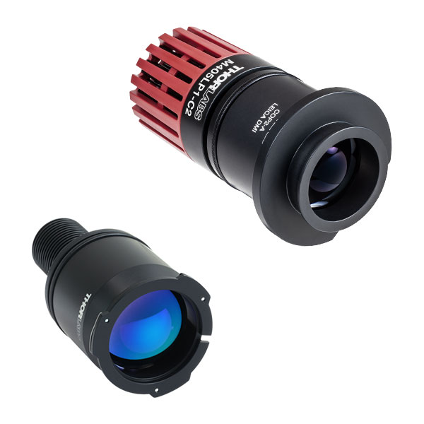
Collimated LEDs for Microscopyb | Fiber- Coupled LEDsc |
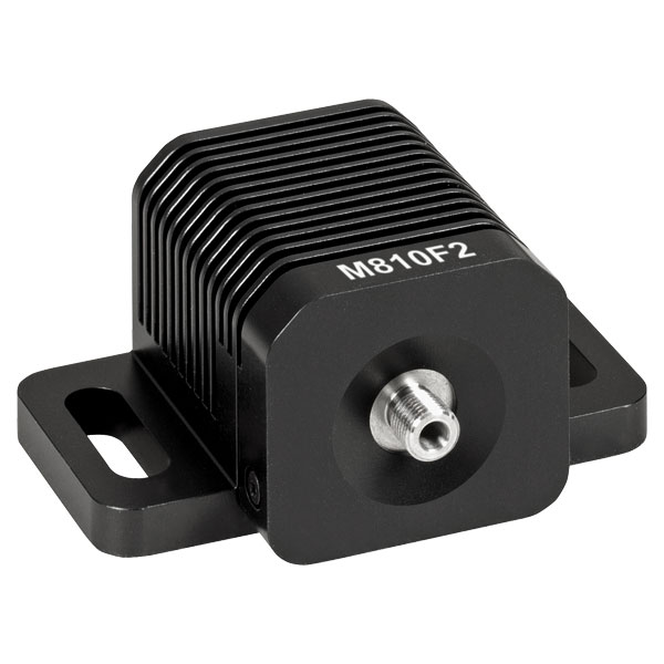
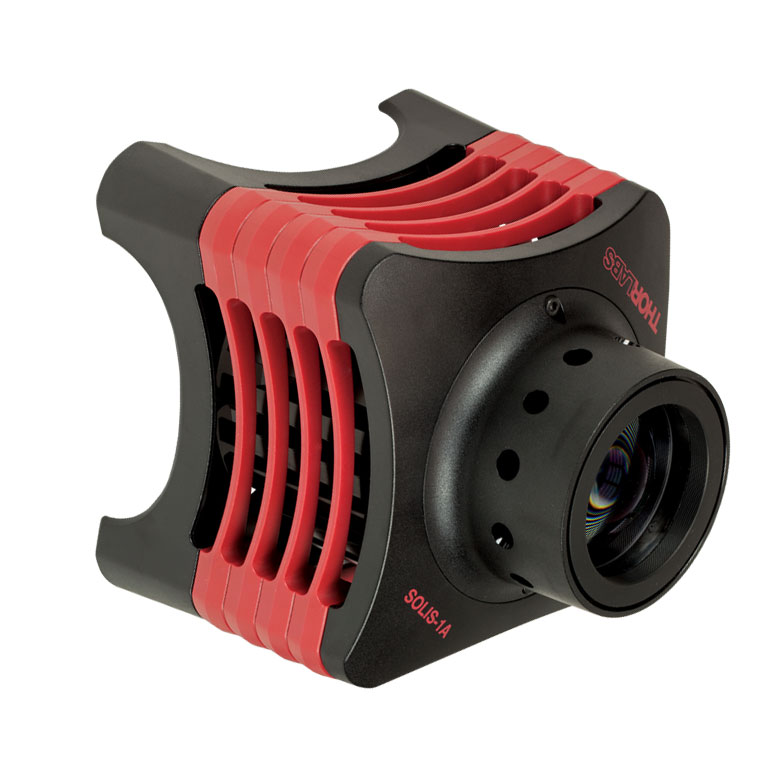
High-Power LEDs for Microscopy | Multi-Wavelength LED Source Optionsd |