 Products Home / Optomechanical Components / Lab Platforms / Motorized High-Load Vertical Translation Stage
Motorized High-Load Vertical Translation Stage
- Motorized Stage with 50 mm (1.97") Vertical Travel
- High Load Capacity of 20 kg (44 lbs)
- Integrated Controller Facilitates Local or Remote Control
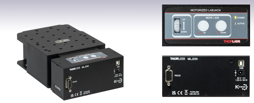
MLJ250
50 mm Vertical Travel Stage with Integrated Controller
Power Supply, USB, and RS232 Ports
Manual Control Keypad


Please Wait
| Key Specificationsa | |
|---|---|
| Travel | 50 mm (1.97") |
| Load (Max) | 20 kg (44 lbs) |
| Velocity (Max) | 3.0 mm/s (All Loads) |
| Pitch/Roll Errorb | <500 µRad |
| Unidirectional Repeatabilityc | <10 µm |
| Deck Parallelism | <150 µm Over Full Range of Travel |
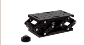
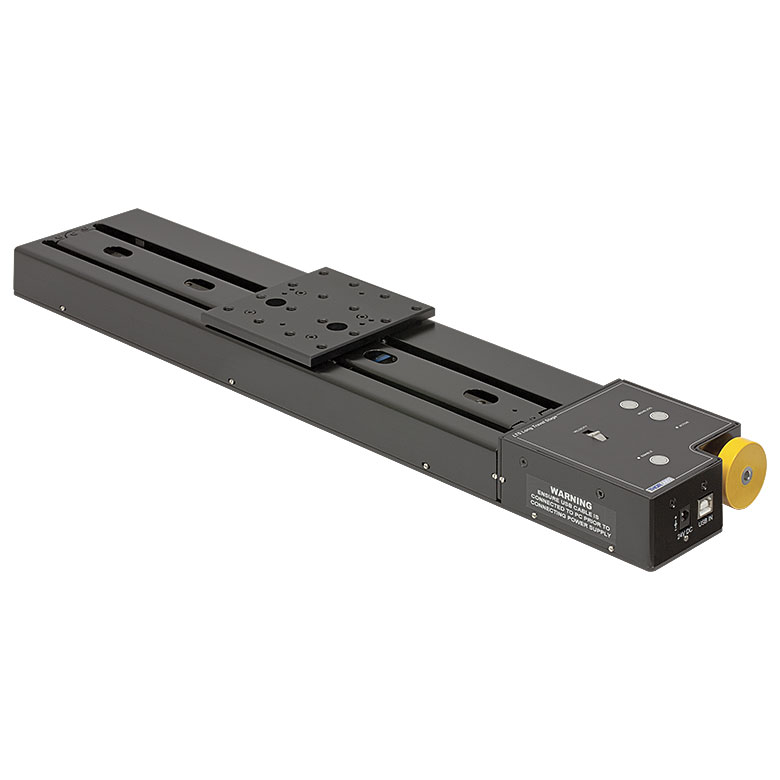
Click to Enlarge
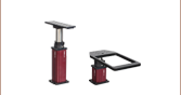
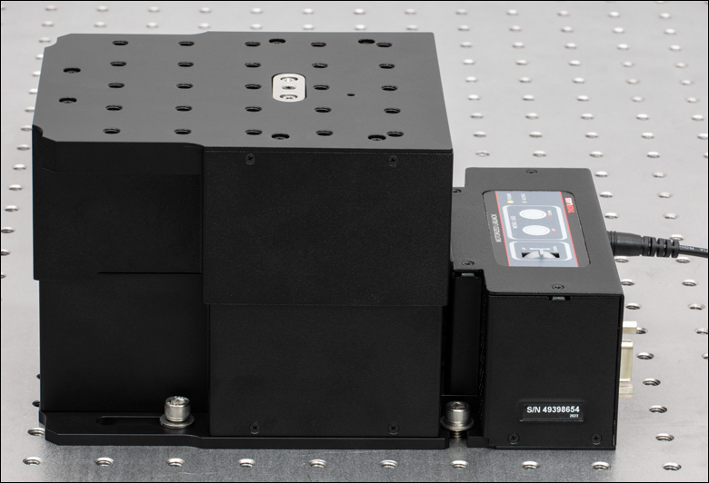
The Fully Extended MLJ250(/M) Mounted onto a Nexus Optical Table by 1/4"-20 (M6 x 1.0)
Cap Screws (Not Included)
Features
- Motorized High-Load Vertical Translation Stage with Local or Remote Control
- USB and RS232 Computer Connections
- Smooth, Stepper Motor Driven Linear Motion
- Full Kinesis® Software Control Suite (See Kinesis Software Tab for Details)
- Large Mounting Platform with 1/4"-20 (M6 x 1.0) Taps
- Location-Specific Power Supply Included
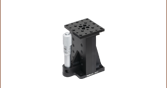
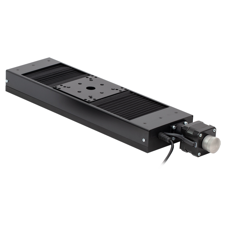
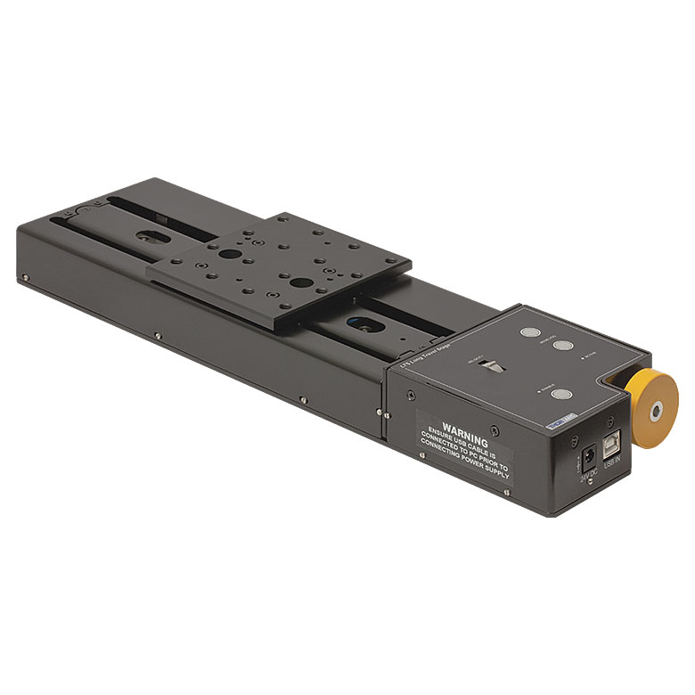
The MLJ250(/M) Motorized Vertical Translation Stage offers up to 50 mm of smooth, stepper motor driven linear height adjustment. Its integrated electronic controller allows for local control or CPU control via our software. This stage provides a rugged, height-adjustable platform ideal for mounting optomechanical sub-assemblies that need vertical positioning. It incorporates a large 5.16" x 5.83" (131.0 mm x 148.0 mm) mounting platform that is capable of moving loads up to 44 lbs (20 kg) at up to 3 mm/s. Guards are fitted to completely eliminate finger traps and other obstructions. These features make it ideal to use as a heavy-duty lab jack.
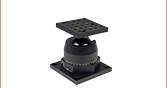
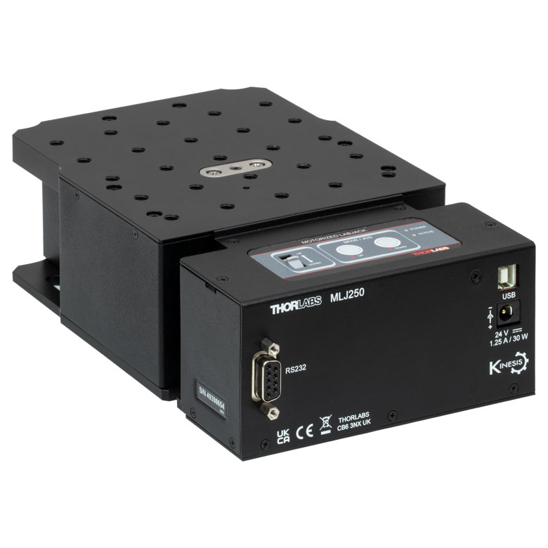
The integrated electronic contoller facilitates local control via the keypad buttons and velocity potentiometer, as seen in the image to the right. Alternatively, the MLJ250(/M) stage can be controlled remotely via USB or RS232 connections (see the Pin Diagram tab for connector information) by utilizing our Kinesis® software suite. Parameter settings can be adjusted on the PC and stored in non-volatile memory within the unit itself. When the unit is next powered up, these settings are applied automatically. This feature is particularly useful when operating the unit manually in the absence of a PC link. Furthermore, the magnetic limit switches can be configured using flexible logic settings.
The stage offers excellent rigidity and platform parallelism. The top plate has twenty-five 1/4"-20 (M6 x 1.0) tapped holes with 0.31" (8.0 mm) depth, while the bottom plate has clearance slots that can be used to mount the stage to an optical breadboard using 1/4"-20 (M6 x 1.0) socket cap screws (not included), as shown to the right. The unit is supplied with a location-specific power supply with an input of 100 to 240 VAC. Please connect the power supply unit (PSU) to the stage before connecting the PSU to a power outlet. A USB cable for connection to a PC is also included.
Calibration Files
Each MLJ250(/M) stage is calibrated at the factory. Calibration enables the controller to correct for any mechanical errors present in the system. Mechanical components, such as the lead screw and linkages, can be machined only within a certain tolerance. These mechanical errors result in deviations of the actual position from the commanded position. However, the deviations are repeatable and can be compensated for using the Kinesis software and included calibration files. These files are used by the Kinesis software to convert the position entered by the user into the required mechanical motion. The calibration files can be downloaded by clicking on the red Docs icon  )
)
Software Control
USB and RS232 connectivity provides simple PC-controlled operation with our Kinesis software package. The Kinesis Software features .NET controls which can be used by 3rd party developers working in the latest C#, Visual Basic, LabView or any .NET compatible languages to create custom applications. For more details the Kinesis software package, please see the Kinesis Software and Kinesis Tutorials tabs for more details.
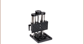
 Click for Details
The 5.16" x 5.83" (131.0 mm x 148.0 mm) top platform of the MLJ250 has twenty-five 1/4"-20 mounting taps. The control keypad for manual control can be seen here.
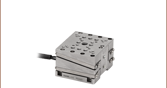
 Click for Details
The 131.0 mm x 148.0 mm (5.16" x 5.83") top platform of the MLJ250/M has twenty-five M6 x 1.0 mounting taps. The control keypad for manual control can be seen here.
| Item # | MLJ250 | MLJ250/M | |
|---|---|---|---|
| Stage Specifications | |||
| Travel | 50 mm (1.97") | ||
| Mounting Taps | 1/4"-20, 0.31" Deep | M6 x 1.0, 8.0 mm Deep | |
| Gear Ratio | 3 to 1 (1 228 800 microsteps = 1 mm Travel) | ||
| Load (Max) | 44 lbs | 20 kg | |
| Moment Load (Max) | 5 N•m (44 in-lb) | ||
| Velocity (Max) | 3.0 mm/s at All Loads | ||
| Resolution (Theoretical) | 0.8 nm | ||
| Deck Parallelism | <150 µm Over Full Range of Travel | ||
| Unidirectional Repeatability (Software Corrected) | <10 µm | ||
| Bidirectional Repeatability (System Backlash) | <50 µm | ||
| Pitch/Roll Error Over 50 mm Travel | <500 µrad | ||
| Accuracy | <30 µm | ||
| Lead Screw Pitch | 1.0 mm | ||
| Controller Specifications | |||
| Microsteps per Full Step | 2048 | ||
| Microsteps per Revolution of Motor | 409 600 | ||
| Motor Drive Voltage | 24 V | ||
| Motor Drive Power | Up to 25 W (Peak) / 12.5 W (Avg.) | ||
| Motor Speeds | Up to 720 RPM | ||
| Motor Specifications | |||
| Step Angle | 1.8° | ||
| Step Accuracy | 5% | ||
| Rated Phase Current | 0.85 A | ||
| Phase Resistance | 5.4 Ω | ||
| Phase Inductance | 5.6 mH | ||
| Holding Torque | 20 N•cm | ||
| Detent Torque | 2.0 N•cm | ||
| Operating Temperature | -20 to 40 °C (Motor Specification Only) | ||
| Input Power Requirements | |||
| Current | 1.25 A | ||
| Voltage | 24 VDC | ||
| Power | 30 W (Peak) | ||
| General | |||
| Dimensions (W x D x H) | Extended | 5.16" x 8.53" x 4.53" | 131.0 mm x 216.7 mm x 115 mm |
| Retracted | 5.16" x 8.53" x 2.56" | 131.0 mm x 216.7 mm x 65.0 mm | |
| Mounting Platform | 5.16" x 5.83" | 131.0 mm x 148.0 mm | |
| Weight | 5.73 lbs | 2.6 kg | |
| Pin | Description |
|---|---|
| 1 | Not Connected |
| 2 | Transmitted Data (Controller Input) |
| 3 | Received Data (Controller Output) |
| 4 | Not Connected |
| 5 | Ground |
| 6 | Not Connected |
| 7 | Clear to Send (CTS) Input |
| 8 | Request to Send (RTS) Output |
| 9 | Not Connected |
Computer Connections
USB Type B

USB Type B to Type A Cable Included
RS232
Our Kinesis® software package drives a wide selection of our motion control devices ranging from small, low-powered, single-channel drivers (such as the K-Cubes™ and T-Cubes™) to high-power, multi-channel, modular 19" rack nanopositioning systems.
The Kinesis Software features .NET controls which can be used by 3rd party developers working in the latest C#, Visual Basic, LabVIEW™, or any .NET compatible languages to create custom applications. Low-level DLL libraries are included for applications not expected to use the .NET framework. A Central Sequence Manager supports integration and synchronization of all Thorlabs motion control hardware.
By providing these common software platforms, Thorlabs has ensured that users can easily mix and match any of the Kinesis-compatible controllers in a single application, while only having to learn a single set of software tools. In this way, it is perfectly feasible to combine any of the controllers from single-axis to multi-axis systems and control all from a single, PC-based unified software interface.
The software package allows two methods of usage: graphical user interface (GUI) utilities for direct interaction with and control of the controllers 'out of the box', and a set of programming interfaces that allow custom-integrated positioning and alignment solutions to be easily programmed in the development language of choice.
Software
Kinesis Version 1.14.47
The Kinesis Software Package, which includes a GUI for control of Thorlabs' Kinesis-compatible controllers.
Also Available:
- Communications Protocol
Kinesis GUI Screen
Thorlabs' Kinesis® software features new .NET controls which can be used by third-party developers working in the latest C#, Visual Basic, LabVIEW™, or any .NET compatible languages to create custom applications.
C#
This programming language is designed to allow multiple programming paradigms, or languages, to be used, thus allowing for complex problems to be solved in an easy or efficient manner. It encompasses typing, imperative, declarative, functional, generic, object-oriented, and component-oriented programming. By providing functionality with this common software platform, Thorlabs has ensured that users can easily mix and match any of the Kinesis controllers in a single application, while only having to learn a single set of software tools. In this way, it is perfectly feasible to combine any of the controllers from the low-powered, single-axis to the high-powered, multi-axis systems and control all from a single, PC-based unified software interface.
The Kinesis System Software allows two methods of usage: graphical user interface (GUI) utilities for direct interaction and control of the controllers 'out of the box', and a set of programming interfaces that allow custom-integrated positioning and alignment solutions to be easily programmed in the development language of choice.
For a collection of example projects that can be compiled and run to demonstrate the different ways in which developers can build on the Kinesis motion control libraries, click on the links below. Please note that a separate integrated development environment (IDE) (e.g., Microsoft Visual Studio) will be required to execute the Quick Start examples. The C# example projects can be executed using the included .NET controls in the Kinesis software package (see the Kinesis Software tab for details).
 |
Click Here for the Kinesis with C# Quick Start Guide Click Here for C# Example Projects Click Here for Quick Start Device Control Examples |
|
LabVIEW
LabVIEW can be used to communicate with any Kinesis- or APT-based controller via .NET controls. In LabVIEW, you build a user interface, known as a front panel, with a set of tools and objects and then add code using graphical representations of functions to control the front panel objects. The LabVIEW tutorial, provided below, provides some information on using the .NET controls to create control GUIs for Kinesis- and APT-driven devices within LabVIEW. It includes an overview with basic information about using controllers in LabVIEW and explains the setup procedure that needs to be completed before using a LabVIEW GUI to operate a device.
 |
Click Here to View the LabVIEW Guide Click Here to View the Kinesis with LabVIEW Overview Page |
|
Motorized Linear Translation Stages
Thorlabs' motorized linear translation stages are offered in a range of maximum travel distances, from a stage with 20 µm of piezo translation to our 600 mm direct drive stage. Many of these stages can be assembled in multi-axis configurations, providing XY or XYZ translation. For fiber coupling applications, please see our multi-axis stages, which offer finer adjustment than our standard motorized translation stages. In addition to motorized linear translation stages, we offer motorized rotation stages and goniometers. We also offer manual translation stages.
Piezo Stages
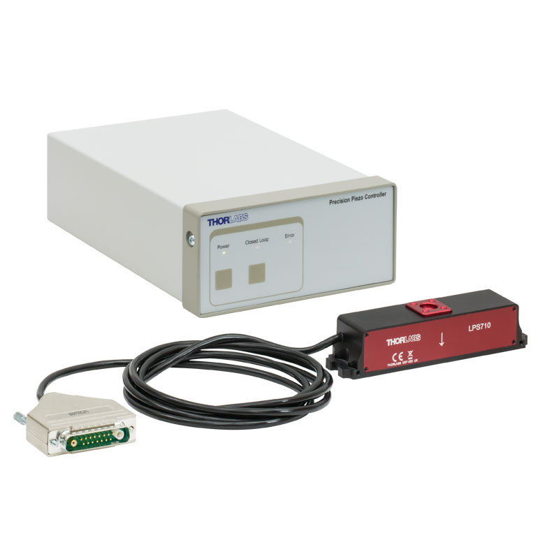
These stages incorporate piezoelectric elements in a variety of drive mechanisms. ORIC® stages incorporate piezo inertia drives that use "stick-slip" friction properties to obtain extended travel ranges. Our Nanoflex™ translation stages use standard piezo chips along with manual actuators. Elliptec® stages use resonant piezo motors to push and pull the moving platform through resonant elliptical motion. Our LPS710E z-axis stage features a mechanically amplified piezo design and includes a matched controller.
| Piezoelectric Stages | ||||
|---|---|---|---|---|
| Product Family | ORIC® PDXZ1 Closed-Loop 4.5 mm Vertical Stage |
ORIC® PD2 Open-Loop 5 mm Stage |
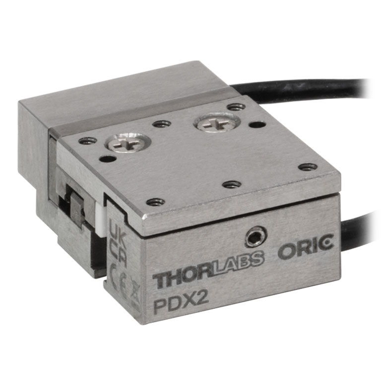
ORIC® PDX2 Closed-Loop 5 mm Stage |
|
| Click Photo to Enlarge |
 |
 |
 |
|
| Travel | 4.5 mm | 5 mm | ||
| Speed | 1 mm/s (Typ.)a | 10 mm/s (Typ. Max)b | 8 mm/s (Typ.)c | |
| Drive Type | Piezoelectric Inertia Drive | |||
| Possible Axis Configurations | Z | X, XY, XYZ | ||
| Mounting Surface Size |
45.0 mm x 42.0 mm | 13 mm x 13 mm | ||
| Additional Details | ||||
| Piezoelectric Stages | |||||
|---|---|---|---|---|---|
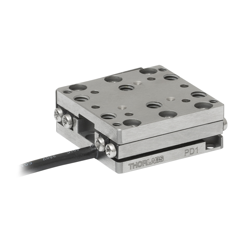
| Product Family | ORIC® PD1 Open-Loop 20 mm Stage |
ORIC® PD1D Open-Loop 20 mm Monolithic XY Stage |
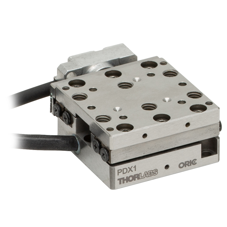
ORIC® PDX1 Closed-Loop 20 mm Stage |
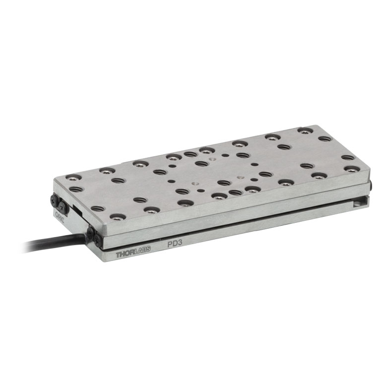
ORIC® PD3 Open-Loop 50 mm Stage |
|
| Click Photo to Enlarge |
 |
 |
 |
 |
|
| Travel | 20 mm | 50 mm | |||
| Speed | 3 mm/s (Typ. Max)a | 20 mm/s (Typ. Max)b | 10 mm/sc | ||
| Drive Type | Piezoelectric Inertia Drive | ||||
| Possible Axis Configurations | X, XY, XYZ | XY, XYZ | X, XY, XYZ | X, XY, XYZ | |
| Mounting Surface Size |
30 mm x 30 mm | 80 mm x 30 mm | |||
| Additional Details | |||||
| Piezoelectric Stages | ||||||
|---|---|---|---|---|---|---|
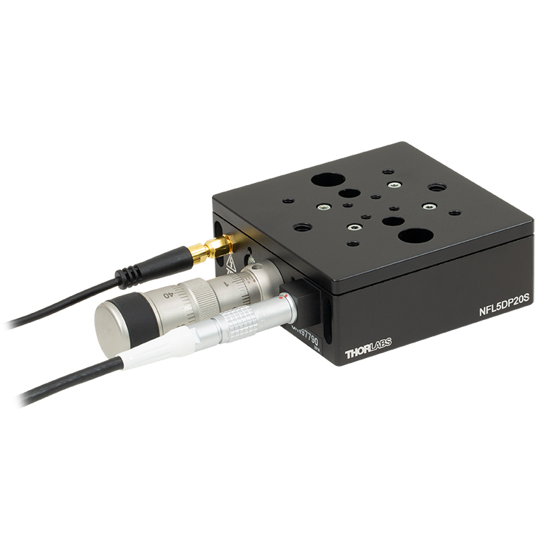
| Product Family | Nanoflex™ 20 µm Stage with 5 mm Actuator |
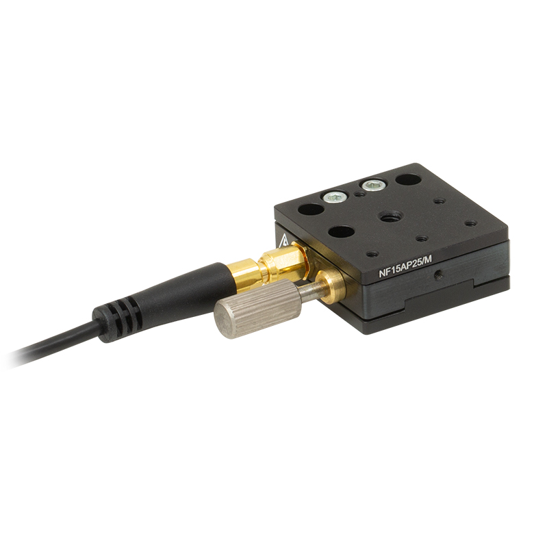
Nanoflex™ 25 µm Stage with 1.5 mm Actuator |
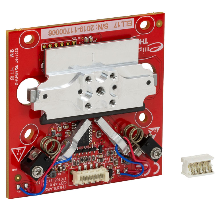
Elliptec® 28 mm Stage | Elliptec® 60 mm Stage | LPS710E 1.1 mm Vertical Stage | |
| Click Photo to Enlarge |
 |
 |
 |
 |
 |
|
| Travel | 20 µm + 5 mm Manual | 25 µm + 1.5 mm Manual | 28 mm | 60.0 mm | 1.1 mm | |
| Maximum Velocity | - | 180 mm/s | 90 mm/s | - | ||
| Drive Type | Piezo with Manual Actuator | Resonant Piezoelectric Motor | Amplified Piezo | |||
| Possible Axis Configurations | X, XY, XYZ | X | Z | |||
| Mounting Surface Size | 75 mm x 75 mm | 30 mm x 30 mm | 15 mm x 15 mm | 21 mm x 21 mm | ||
| Additional Details | ||||||
Stepper Motor Stages
These translation stages feature removable or integrated stepper motors and long travel ranges up to 300 mm. Many of these stages either have integrated multi-axis capability (PLSXY) or can be assembled into multi-axis configurations (PLSX, LNR Series, NRT Series, and LTS Series stages). The MLJ150 stage also offers high load capacity vertical translation.
| Stepper Motor Stages | |||||
|---|---|---|---|---|---|
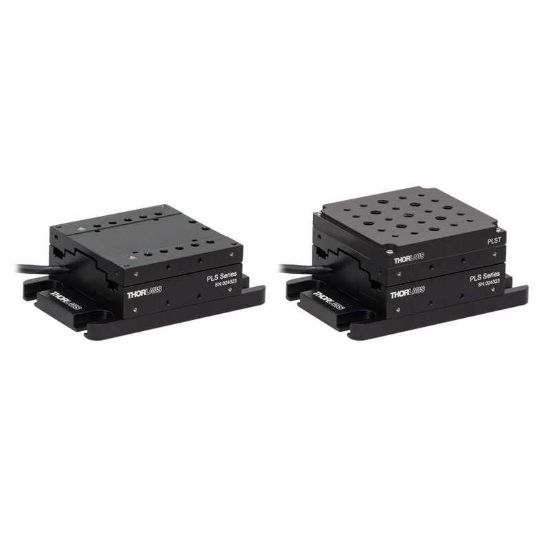
| Product Family | PLSX with and without PLST(/M) Top Plate 1" Stage |
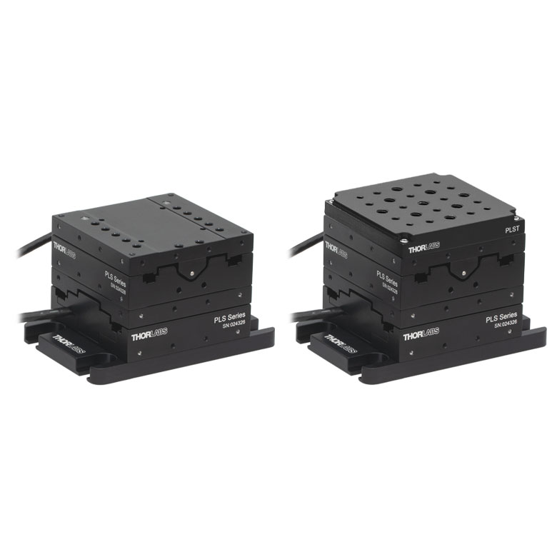
PLSXY with and without PLST(/M) Top Plate 1" Stage |
LNR Series 25 mm Stage |
LNR Series 50 mm Stage |
|
| Click Photo to Enlarge |
 |
 |
 |
 |
|
| Travel | 1" | 25 mm | 50 mm | ||
| Maximum Velocity | 7.0 mm/s | 2.0 mm/s | 50 mm/s | ||
| Possible Axis Configurations |
X, XY | X, XY, XYZ | X, XY, XYZ | ||
| Mounting Surface Size |
3" x 3" | 60 mm x 60 mm | 100 mm x 100 mm | ||
| Additional Details | |||||
| Stepper Motor Stages | ||||||
|---|---|---|---|---|---|---|
| Product Family | NRT Series 100 mm Stage |
NRT Series 150 mm Stage |
LTS Series 150 mm Stage |
LTS Series 300 mm Stage |
MLJ250 50 mm Vertical Stage |
|
| Click Photo to Enlarge |
 |
 |
 |
 |
 |
|
| Travel | 100 mm | 150 mm | 150 mm | 300 mm | 50 mm | |
| Maximum Velocity | 30 mm/s | 50 mm/s | 3.0 mm/s | |||
| Possible Axis Configurations |
X, XY, XYZ | X, XY, XYZ | Z | |||
| Mounting Surface Size |
84 mm x 84 mm | 100 mm x 90 mm | 148 mm x 131 mm | |||
| Additional Details | ||||||
DC Servo Motor Stages
Thorlabs offers linear translation stages with removable or integrated DC servo motors. These stages feature low profiles and many can be assembled in multi-axis configurations.
| DC Servo Motor Stages | ||||
|---|---|---|---|---|
| Product Family | MT Series 12 mm Stages |
PT Series 25 mm Stages |
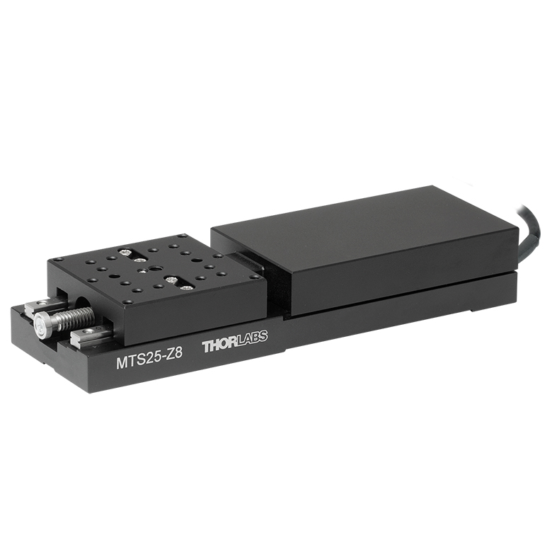
MTS Series 25 mm Stage |
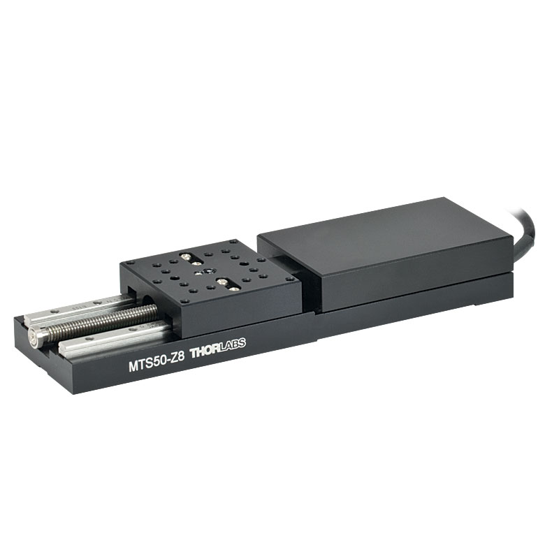
MTS Series 50 mm Stage |
| Click Photo to Enlarge |
 |
 |
 |
 |
| Travel | 12 mm | 25 mm | 25 mm | 50 mm |
| Maximum Velocity | 2.6 mm/s | 2.4 mm/s | ||
| Possible Axis Configurations | X, XY, XYZ | X, XY, XYZ | ||
| Mounting Surface Size |
61 mm x 61 mm | 101.6 mm x 76.2 mm | 43 mm x 43 mm | |
| Additional Details | ||||
| DC Servo Motor Stages | ||||
|---|---|---|---|---|
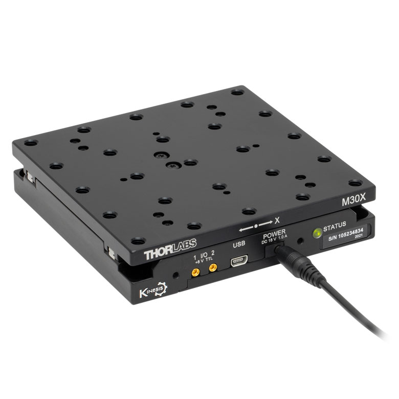
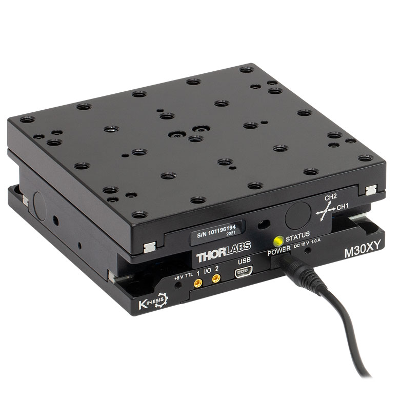
| Product Family | M30 Series 30 mm Stage |
M30 Series 30 mm Monolithic XY Stage |
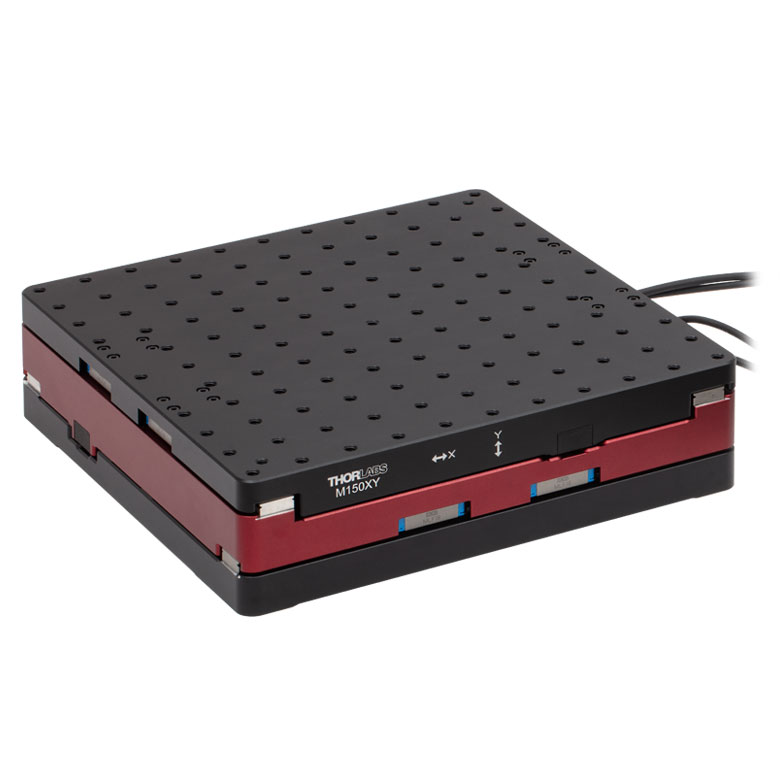
M150 Series 150 mm XY Stage |
KVS30 30 mm Vertical Stage |
| Click Photo to Enlarge |
 |
 |
 |
 |
| Travel | 30 mm | 150 mm | 30 mm | |
| Maximum Velocity | 2.4 mm/s | X-Axis: 170 mm/s Y-Axis: 230 mm/s |
8.0 mm/s | |
| Possible Axis Configurations | X, Z | XY, XZ | XY | Z |
| Mounting Surface Size |
115 mm x 115 mm | 272.4 mm x 272.4 mm | 116.2 mm x 116.2 mm | |
| Additional Details | ||||
Direct Drive Stages
These low-profile stages feature integrated brushless DC servo motors for high speed translation with zero backlash. When no power is applied, the platforms of these stages have very little inertia and are virtually free running. Hence these stages may not be suitable for applications where the stage's platform needs to remain in a set position when the power is off. We do not recommend mounting these stages vertically.
| Direct Drive Stages | |||||
|---|---|---|---|---|---|
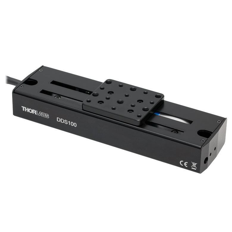
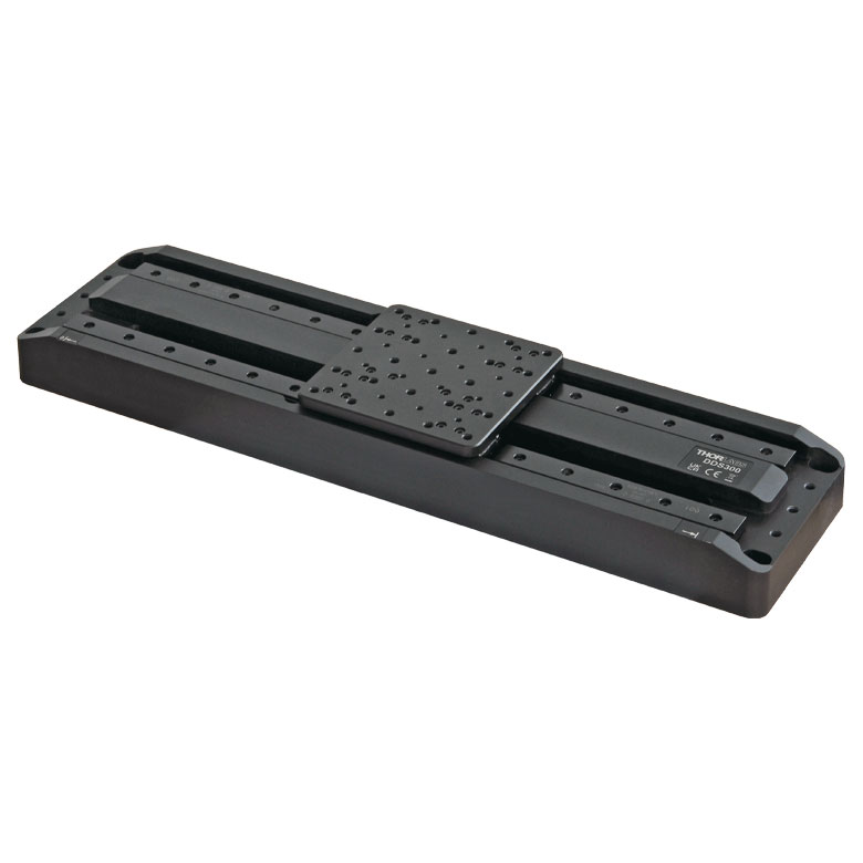
| Product Family | DDS Series 50 mm Stage |
DDS Series 100 mm Stage |
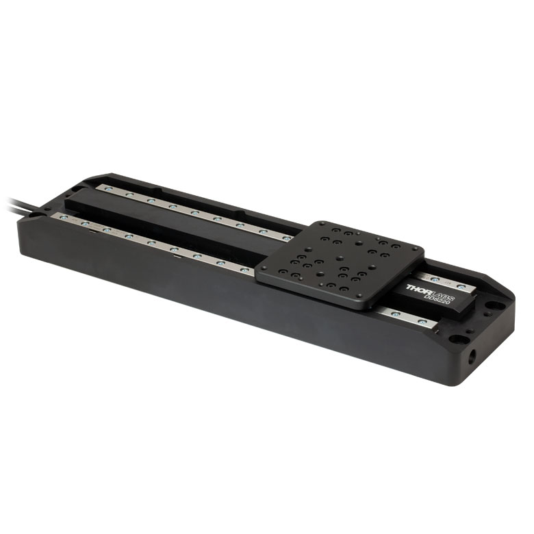
DDS Series 220 mm Stage |
DDS Series 300 mm Stage |
DDS Series 600 mm Stage |
| Click Photo to Enlarge |
 |
 |
 |
 |
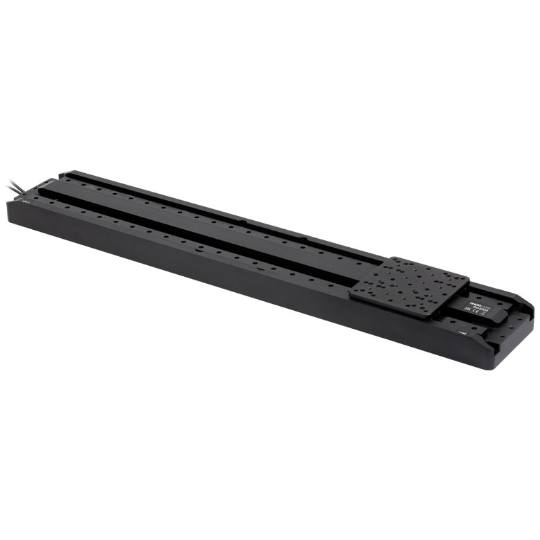 |
| Travel | 50 mm | 100 mm | 220 mm | 300 mm | 600 mm |
| Maximum Velocity | 500 mm/s | 300 mm/s | 400 mm/s | 400 mm/s | |
| Possible Axis Configurations | X, XY | X, XY | X | X | |
| Mounting Surface Size | 60 mm x 52 mm | 88 mm x 88 mm | 120 mm x 120 mm | ||
| Additional Details | |||||
| Posted Comments: | |
Nikolai Schröder
(posted 2024-01-30 11:35:15.06) Dear Sir or Madam,
we have the Motorized High-Load Vertical Translation Stage in our lab. Is it possible to control the stage with an Aerotech-controller?
Thanks a lot and best from Zurich,
Nikolai Schröder user
(posted 2023-07-03 14:15:04.563) Hi, is there any way to connect the MLJ150/M to the KIM101 controller, in order to control it ? user
(posted 2023-06-16 08:21:48.93) Hello, I'm trying to connect the device on the Kenesis Software but all i get is " Device not responding ". However, it worked perfectly yesterday. What can I do ? Thank you. fguzman
(posted 2023-06-16 11:56:58.0) Thank you for your inquiry, I am sorry to hear this is happening. The 'device not responding' error can occur for a number of reasons. We will reach out to you directly to help troubleshoot further. user
(posted 2023-05-21 13:40:22.13) I am currently trying to use my c++ program to control MLJ150/M, but I have been generating the following error in 'Thorlabs. MotionControl. IntegratedStepperMotors. dll': (0xc0000139) 'Entry Point Not Found'.
I am sure that I have made the correct configuration in my VS project and have copied 'Thorlabs.MotionControl. IntegratedStepperMotors.dll' to the corresponding folder.
My Windows10 system is 64 bit, and I have downloaded the 64 bit Kinesis software and it runs normally.
How should I use C++ programs correctly to control MLJ150/M? do'neill
(posted 2023-05-22 10:13:03.0) Response from Daniel at Thorlabs. I will reach out to you directly to discuss and troubleshoot your application. Gabriel Chiritoi
(posted 2022-10-18 08:14:34.38) I have a motorized labjack MLJ150/M. I am trying to control it via Kinesis software using USB cable but this seems impossible, always getting "Device not responding". I also tryed the APT application but it's very unstable (crashing when connecting the stage, not responding, in the apt config not be able to set the serial number and select the stage model). Is there anything I could try ? DJayasuriya
(posted 2022-10-18 09:33:34.0) Thank you for your inquiry. We have got in touch with you directly to troubleshoot. user
(posted 2022-03-03 10:59:55.54) Hello, we are considering using two of these translation stages opposed to each other in a compression experiment, to compress a flexible object for a precise distance symmetrically from two sides.
Can these stages be operated upside-down or sideways? Many thanks in advance cwright
(posted 2022-03-04 09:34:00.0) Response from Charles at Thorlabs: Thank you for contacting us. This device has not been characterised for use in any other configuration than its default orientation. We will reach out to you to discuss your application and how we can best help you. Sergio Gonzalez
(posted 2021-05-28 11:22:42.84) I have a motorized labjack MLJ150/M. I am trying to control it via Kinesis software using USB cable but this seems impossible, always getting "Device not responding". Is there anything I could try ? jcater
(posted 2021-06-01 12:23:34.0) Response from Jack at Thorlabs: Thank you for your inquiry, I am sorry to hear this is happening. The 'device not responding' error can occur for a number of reasons. We will reach out to you directly to help troubleshoot further. user
(posted 2020-04-22 23:02:27.23) Hello, I have a question regarding the gearbox ratio of the MLJ050/M labjack. The specifications on the catalogue page say the gearbox ratio is 3 to 1. Additionally, the default settings XML file for Kinesis specifies a gearbox ratio of 3 to 1. However, the Thorlabs APT Communication Protocol document says the gearing is 1 mm/turn (i.e. ratio of 1 to 1). Can you please advise which is correct? Thank you! DJayasuriya
(posted 2020-04-24 06:50:20.0) Response from Dinuka at Thorlabs: Thanks for your query. Yes the gear box ratio is 3:1, from the APT protocol document, 1mm/turn is not the gear ratio relates to the encoder. The trinamics encoder gives 409600 micro‐steps per revolution. i.e. a 1 mm move requires 1228800 microsteps = 409600 microsteps * 3. Hope this helps. Salman Naqvi
(posted 2019-10-24 20:34:32.427) Hi,
We have half a dozen of these labjacks in our lab which speaks of their utility for our task. Sadly, we have started to experience issues driving them to the desired position. Randomly during some motion, labjack would make a loud beep and instead of throwing any error, stop midway but report that it has reached the destination! This makes the stage extremely unreliable for repeatable measurements. I haven't been able to find a way to troubleshoot it. For reference, we have been sending commands 0x0480 and 0x0453 via serial port on Windows 8. Can you please reach back to me and help us fix the problem if a fix exists?
Thanks
- Salman Naqvi
Hardware Engineering, Apple Inc
Cupertino, CA cwright
(posted 2019-10-28 04:13:42.0) Hello Salman, I'm sorry to hear you are having these issues but I am sure we can help resolve this. I will reach out to you directly about this. user
(posted 2019-08-13 10:28:06.373) Does the stage need to be re-calibrated after extensive use? (0-40mm travel distance, 20 times/ day) AManickavasagam
(posted 2019-08-14 09:07:12.0) Response from Arunthathi at Thorlabs: Thanks for your query. This will also depend on how long you have used the stage for, the load on it and etc. Typically we do not have a calibration schedule for this stage. FYI you can download the calibration file from the website or alternatively please contact your local tech support office with the serial number of your stage and we will be able to provide the calibration file. user
(posted 2019-07-19 15:25:46.223) When I connected this product with Kineses,the PC can not get response from the labjack,and the diagnostic log of kineses showed "Device not reponding(Error Code-33)".I don't know why this happened.Can you please help me to find the problem and solution,thank you. AManickavasagam
(posted 2019-07-26 03:46:33.0) Response from Arunthathi at Thorlabs: Thanks for reaching out to us. ‘Error code 33’ (indicating a comms failure) usually appears when using old versions of Kinesis with new hardware (firmware). This is displayed as a Generic Error in .NET API help file. This usually resolves when using the latest software; updating the firmware, power cycling the device and also restarting your computer for the update to fully take effect. If you still have any issues please contact your local tech support office for further help. Yanhua Ma
(posted 2019-07-03 10:37:08.87) Hello, I am trying to control labjack MLJ150/M using the latest version of kinesis. When attempting to load the jack (connected by USB), kinesis fails with error "Device not responding (Error Code- 33)". How do I solve this problem? AManickavasagam
(posted 2019-07-03 09:21:44.0) Response from Arunthathi at Thorlabs: Thanks for contacting us. I have reached out to you directly to troubleshoot the issue you have. Sang Min Lee
(posted 2019-04-23 08:50:08.047) At first, the device was operating normally. It is currently recognized but does not work properly in kinesis. Attach the following log file contents. What is the problem and how can it be solved?
2019-04-23 17:40:18.082 Diagnostic $100013 Opening Device Collection
2019-04-23 17:40:18.082 Diagnostic $100014 Create Device: Thorlabs.MotionControl.DeviceManagerCLI.DeviceChannels
2019-04-23 17:40:18.082 Info $301100 Loaded Device Settings
SettingsName = MLJ150/M Labjack
DeviceAlias =
CollateLogging = False
OutputDebugMask = StdOutput
OutputLogMask = StdLogging
LoadSettingsOption = UseFileSettings
2019-04-23 17:40:18.082 Info $301112 Storing Device Configurations Device = 49954940
2019-04-23 17:40:18.083 Diagnostic $1146 RegisterDeviceSettingsFactory
2019-04-23 17:40:18.083 Info $1100 Loaded Device Settings
CollateLogging = 0
DeviceAlias =
LoadSettingsOption = 2
MustUseDeviceUnits = 0
OutputDebugMask = 7
OutputLogMask = 31
SettingsName = MLJ150/M Labjack
2019-04-23 17:40:18.083 Info $1112 Storing Device Configurations Device = 49954940
2019-04-23 17:40:18.086 Diagnostic 49954940 Processing Message: Value = ::Homed
2019-04-23 17:40:18.086 Diagnostic 49954940 Changing State: Value = IdleState
2019-04-23 17:40:18.237 Diagnostic 49954940 LoadDevice Success
Device = 49954940
Handle = 0F80FBF0
2019-04-23 17:40:22.615 Error 49954940 Device not responding Error Code = 33
2019-04-23 17:40:22.934 Diagnostic $100015 Opened Device Collection rmiron
(posted 2019-04-24 11:08:50.0) Response from Radu at Thorlabs: Error code 33 suggests an USB communications-related problem. I will contact you directly in order to assist you in troubleshooting your device. Hanna Dierks
(posted 2019-04-11 04:57:13.3) HI!
I'm also interested in the long term position stability of the MLJ150/M. In your response to nitzan_chamiel (2019-02-28) you mentioned that you are currently running some tests on this.
Are there any (preliminary) results yet? For my experiment I would need stability in the sub micrometer range over several days, with a load of about 6kg.
Is there any (e.g mechanical) creep you know of?
Thanks in advance! rmiron
(posted 2019-04-11 06:56:07.0) Response from Radu at Thorlabs: Hello, Hanna. The testing that we ran was not extensive enough to enable us to post a specification on the website. Furthermore, it was not run in an isothermal environment. With that being said, I expect that the stage will drift by more than 1 um over several days. I will contact you directly in order to share the results I shared with Nitzan. nitzan_chamiel
(posted 2019-02-28 00:00:31.263) Hello,
In my application I plan to use the MLJ150 for coarse z adjustment, and an additional LPS710E (piezo Z stage) on top of it for fine z adjustment.
What is the stability of the MLJ150 when not moving?
Also, would I get higher stability with power off?
Thanks you,
Nitzan rmiron
(posted 2019-02-28 05:01:24.0) Response from Radu at Thorlabs: Hello Nitzan. At the moment, we do not have sufficient test data in order to specify the stability of this stage. With that being said, we ran two stability tests for it last week. I will contact you directly in order to share this data with you. We think that it will be more stable if powered off, but this might depend on the load place on it and again, we do not have sufficient data to be certain that this is the case. lebouquj
(posted 2019-02-21 14:00:33.18) We would like to control this device via the RS232 with a socket from a C program. We could not find the format and list of accepted commands in the existing documentation. Do you have it ? Thanks. rmiron
(posted 2019-02-22 07:29:39.0) Response from Radu at Thorlabs: The documentation of our serial commands protocol can be found here: https://www.thorlabs.com/Software/Motion%20Control/APT_Communications_Protocol.pdf
All the public commands are listed in that document. The protocol uses uint8 (hexadecimal) bytes, an 115200/8-N-1 configuration and no terminating bytes. 3206302534
(posted 2018-12-19 18:48:33.95) I do want to konw how many μsteps is 50mm divided to? rmiron
(posted 2018-12-19 10:32:10.0) Response from Radu at Thorlabs: In MLJ150, 1 mm corresponds to 409600 μsteps. Therefore, 50 mm correspond to 20480000 μsteps. I will suggest internally that our serial communications protocol's documentation gets updated such that it mentions this conversion ratio. akuznetsov
(posted 2017-11-15 22:09:15.357) Is this another windows ONLY product or does RS-232 port mean that it can actually be used on a Mac with USB to RS-232 adapter? There are a lot of Thorlabs products >$1000 that only have a USB interface and Kinesis/APT software which means I can't use them on my bench which requires a Mac to control the device under test and as a result requires Mac controllable hardware. bwood
(posted 2017-11-17 05:02:24.0) Response from Ben at Thorlabs: Thanks you for your question. The MLJ150 can be controlled completely through the RS232 connector, so it should be suitable for your application. I would like to note that while APT/Kinesis requires Windows, all devices controlled with this software can also be controlled through serial communications, as per the protocol we offer in the software section. Furthermore, most controllers and devices have auxiliary I/O options, as an alternative to USB control. oavramio
(posted 2017-11-10 12:31:10.803) I am currently trying to develop an experimental set up for precise compression experiments. Thus, I am looking for a very precise vertical translation stage.Although I am very interesting in the motorised labjack MLJ050 devise I still need to know some more things:
Which is the actual minimum velocity that the devise can achieve.
A theoretical resolution of 0.8 nm and an accuracy of 30 micrometers is reported in the specs of the devise. What does this actually mean?
How precisely would I be able to control the motor in terms of 1) Velocity, 2)Position. Would I be able, for instance, to control the exact number of steps of the motor I need him to do? bwood
(posted 2017-11-14 06:15:47.0) Response from Ben at Thorlabs: The theoretical minimum velocity is that which can be commanded by our motion control software. However, at low velocities the motion of any 2-phase stepper motor will become unstable. As you reduce the velocity of the stage, the movement may seem to microscopically ‘stop-start’ depending on the application’s requirements. This is due to the time between motor phases increasing to produce this ultra-low velocity which consequently leads to the motor stalling if there are torque hotspots, where say the pitch of the leadscrew is not perfect. This will vary between each model as at this slow speed any irregularities in the stage are emphasised. This would also be heavily dependent upon the load employed. This means it is hard to define the lower limits of the velocity. The theoretical resolution is the distance traveled in one microstep, however for the reasons above, moving by a set number of microsteps is impossible. The <30 µm value is the achievable accuracy of the stage. lorenzo.alligo
(posted 2017-02-24 08:31:47.267) I have a motorized labjack MLJ050, and having an issue when I launch the APTuser application. It give me an error that say "failed to load application settings. nConfiguration System failed to inizialize." I'm using a 64-bit software on a 64-bit system bhallewell
(posted 2017-02-27 06:43:30.0) Response from Ben at Thorlabs: Thank you for posting this feedback. We believe that this is typically associated with a corrupt install. I will contact you directly to make sure this is working for you. Ian.Lloyd1262
(posted 2017-02-07 10:19:01.573) I have a motorized labjack MLJ050/M that I would like to control using LabVIEW. I have followed your great tutorials and have got it working using ActiveX. I can not get it working using .NET I keep getting the message No suitable devices found. I am able to connect with the device using your Kinesis program. What could I e doing wrong?
Thanks
Ian bhallewell
(posted 2017-02-09 09:54:27.0) Response from Ben at Thorlabs: I would firstly recommend testing the device in the Kinesis application first, to ensure the stage is communicating with your PC correctly. When using the .NET framework please make sure you have copied over all Kinesis .dlls into your project & select the Lab Jack .NET control. We have some steps outlined within the following guide.
https://www.thorlabs.com/Software/Motion%20Control/KINESIS/Kinesis-Labview.pdf
I'd further recommend ensuring that you have the correct version of Kinesis installed which matches your OS & version of LabVIEW. jingfang.wan
(posted 2016-05-06 08:39:43.787) I want to use the labjack on a moving device. Possible to provide a battery driven / wireless version? bwood
(posted 2016-05-09 03:48:21.0) Response from Ben at Thorlabs: Thank you for your feedback. Unfortunately, we do not currently offer a battery alternative to the mains power supply for the LabJack. However, we would be happy to discuss your application with you, to see what advice we an give here. If you wish to do so, I can be contacted at techsupport.uk@thorlabs.com. giuseppe.moschetti
(posted 2016-02-16 13:03:48.463) is Deck Parallelism a static error, i.e. can it be corrected? Is it equivalent to straightness of the axes?
We are concern about losing our x and y positioning when moving the motor up and down.
Thanks
Giuseppe bwood
(posted 2016-02-17 05:56:43.0) Response from Ben at Thorlabs: Thank you for your feedback. The deck parallelism is a static parallelism measurement, so you should be able to correct for this. Please note, there will be a pitch/yaw error over the travel, which we specify over 2" (50mm) as <500 µRad Silvernightwave
(posted 2014-01-15 17:43:51.26) Thank you!
I fixed it with the callback method and set everything bwait=false. Now everything works.
But most important: Thanks for the hint, that there excists a help file with all the definitions. That i didnt know. I only knew the developer support area.
so thanks a lot!
best regards Silvernightwave
(posted 2014-01-14 17:31:22.09) Hello,
i'm using Labview to control the Motor. Unfortunatly during homing or moving (which takes 5-6 seconds) my Labview software isn't responding.
Do you have any idea how to fix it? (Even in a simple software, labview isn't responding at all, not only the frontpanel e.g., it's the hole software including change between front and block diagram e.g.).
Second question about a "is busy" function: Is there a command i could use to check if the system is still moving or if it is finished? I only know about the callback option.
What is the "bwait" option at the command "MoveAbsolute"? I could not find out what this option changes.
best regards msoulby
(posted 2014-01-15 06:50:06.0) Response from Mike at Thorlabs: All of the move commands have a bWait Boolean property. When bWait is set to TRUE then the move method will return only after the move has completed, the program flow will be halted until the move has completed. If bWait is set to FALSE then the method will return as soon as the move has initiated, allowing the program flow to continue without waiting for the move to complete. In labview setting bWait to TRUE may cause the GUI or front panel to freeze up until the move has completed, which will explain the 5-6 second wait you are experiencing. It is more efficient programming practice to set bWait to 'False' and respond to the MoveComplete event. This event driven approach allows your application to service other tasks while the motors are moving and will prevent your front panel from freezing up during the move. An alternative to the MoveComplete event would be to poll the status of the motor, to do this you would need to use the motor method LLGetStatusBits, details of which can be found in the APT server help file under Programming Guide>> Motor Control>>Motor Control Methods t.nguyen14
(posted 2013-03-03 23:14:31.637) We bought a Thorlabs labjack L490MZ/M from you few years ago, and now we want to calibrate it. But I don't have a calibration file as it is requested by ATP config software for calibarion.
Could you please help to give us a calibration file ?
Here is serial number of our Labjack : 46821236
Thank you very much for your help.
Tuan D Nguyen
Research Assistant
School of Chemical Engineering
The University of Queensland
Australia tcohen
(posted 2013-03-06 14:52:00.0) Response from Tim at Thorlabs to Tuan: Thank you for contacting us. We have calibration files dating back to 08/09/10. For older L490MZ/M we can take the unit in for recalibration. I will contact you to continue this discussion. bdada
(posted 2012-03-16 11:53:00.0) Response from Buki at Thorlabs to macross:
I am sorry to hear about the problems you're experiencing when using the L490MZ. I have addressed your two questions below.
1. It could be that the limit switch has been damaged. We just tested one unit with all the different setting options and it stopped every time even when the switch was ignored. We would be happy to evaluate your stage to see if the switch is broken, but please first verify the default limit switch and homing settings first:
Homing:
Direction - Reverse
Limit Switch - Reverse HW
Zero Offset: 0.2
Velocity: 0.4
Hardware Limit Switches:
Reverse - Switch Makes
Forward - Switch Makes
2. If you are still able to discover your hardware in APT firmware, please try and reprogram it again. Open APT config and select the Server tab. In here you can try to increase the Enumeration dwell time (how long the APT server spends looking for and initialising devices). Default is 5000ms, try 10000ms and make sure only one usb device is connected.
We have contacted you directly to provide additional assistance and arrange for the return and evaluation of your lab jack, if needed. macross
(posted 2012-03-15 14:26:16.0) Use L490MZ occur two problem.
1.when homing, a stage moves n reverse direction but motor can't stop finally. Because it was not get the reverse limit switch signal. I need your help quickly.
2.after I use APT firmware to flash firmware, I can't see the GUI interface in APT user. bdada
(posted 2012-02-10 19:19:00.0) Response from Buki at Thorlabs to johannes.strauss:
Thank you for your feedback on our motorized lab jack. Due to the scissor action of the stage, you will see the worst 'twist' on the first move, so you will see the error no matter the step size or travel distance. We are currently redesigning this stage to improve the deck parallelism. johannes.strauss
(posted 2012-02-08 02:53:20.0) Deck parallelism (<250µm hole travel range) is pretty much for my application. I need that 2” of total travel range, but for measuring 0.5” is sufficient. So my question: is deck parallelism at 0.5” movement also <250µm or even less? My tolerance is <100µm, is that realizable with your system? bdada
(posted 2011-11-15 18:44:00.0) Response from Buki at Thorlabs.com
Thank you for your feedback. The 1mm/sec velocity is what we specify to ensure positional accuracy. We have contacted you to discuss if other products may be more suitable. For instance, the combination of LTS150 - Integrated 150 mm Travel Stage with a LTSP2 - Z-Axis Bracket would provide 3mm/s vertical velocity with a maximum vertical load capacity of 4kg, with 150mm of travel.
Or the LNR50S - 2" TravelMax Stage with Trapezoidal Stepper and LNR50P2 bracket would provide a maximum velocity of 8mm/s and a maximum vertical load capacity of 10kg, but limited to only 2” of travel.
We have contacted you to provide further support. excelkim.kim
(posted 2011-11-11 06:24:57.0) I have serious problem.
max. 1mm/sec velocity is so slow.
It takes too much time to enter the target position.
Is there any method to increase the velocity.
At your specification, max. rpm is over 700.
I think you could give me the solution.
Thank you. bdada
(posted 2011-09-16 12:33:00.0) Response from Buki at Thorlabs:
The L490MZ is designed such that it will not drop when it is unplugged from the power supply. Please contact TechSupport@thorlabs.com if you have further questions. felipe.aguilarsan
(posted 2011-09-15 17:12:50.0) Hello, I want to know if this product have something like "self locking at rest" for unplugged use in a determined position, thank you. user
(posted 2011-09-14 18:39:47.0) Supose I put a position X, if I unplug or turn off this device it will keep the same position rigidly? Like a self locking or something like that. jjurado
(posted 2011-05-20 13:54:00.0) Response from Javier at Thorlabs to gerbenjoshua: Thank you very much for contacting us. We have not developed drivers and documentation for interfacing our motorized stages with the Linux platform. gerbenjoshua
(posted 2011-05-20 14:53:07.0) Are Linux drivers available? bdada
(posted 2011-03-09 16:04:00.0) Response from Buki:
Thank you for using our feedback tool. The L490MZ is anodized so it is not vacuum compatible. However, we have offered unanodized L490 lab jacks as custom products before. I will contact you directly to discuss your appliction and determine if an unanodized L490MZ is feasible. paulgard
(posted 2011-03-08 19:57:25.0) Is L490-MZ vacuum compatible? |