 Products Home / Motorized Stages / Motorized Linear Stages / ORIC® 20 mm Linear Translation Stage with Ultrasonic Piezoelectric Drive
ORIC® 20 mm Linear Translation Stage with Ultrasonic Piezoelectric Drive

- Linear Ultrasonic Piezo Stage with Closed-Loop Positioning
- 3 kg Horizontal Load Capacity
- Typical Max Speed Up to 100 mm/s
- Stackable Design for Compact 1-, 2-, or 3-Axis Setups
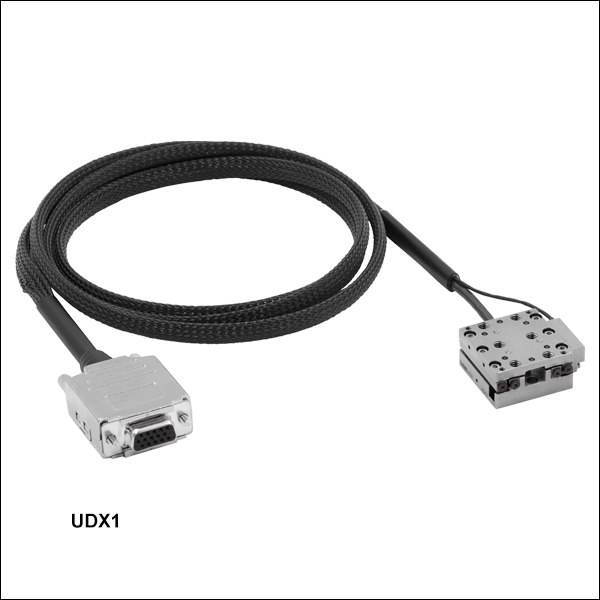
UDX1
Ultrasonic Piezo Stage
with Optical Encoder,
20 mm Travel
UDXC
Ultrasonic Piezo Stage Controller


Please Wait
| ORIC® Piezo Stage Selection Guide |
|---|
| 4.5 mm Piezo Inertia Vertical Translation Stage |
| 5 mm Piezo Inertia Linear Translation Stages |
| 12 mm Piezo Inertia Linear Translation Stages |
| 20 mm Piezo Inertia Linear Translation Stages |
| 20 mm Ultrasonic Piezo Linear Translation Stages |
| 50 mm Piezo Inertia Linear Translation Stages |
| Piezo Inertia Rotation Stages |
| Piezo Inertia Vacuum-Compatible Stages |
| Quick Links |
|---|
| Linear Stage with Optical Encoder |
| Adapters |
| Controller |
Click to Enlarge
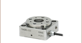
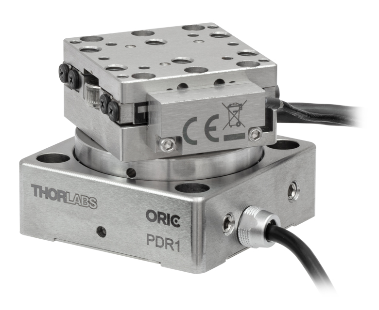
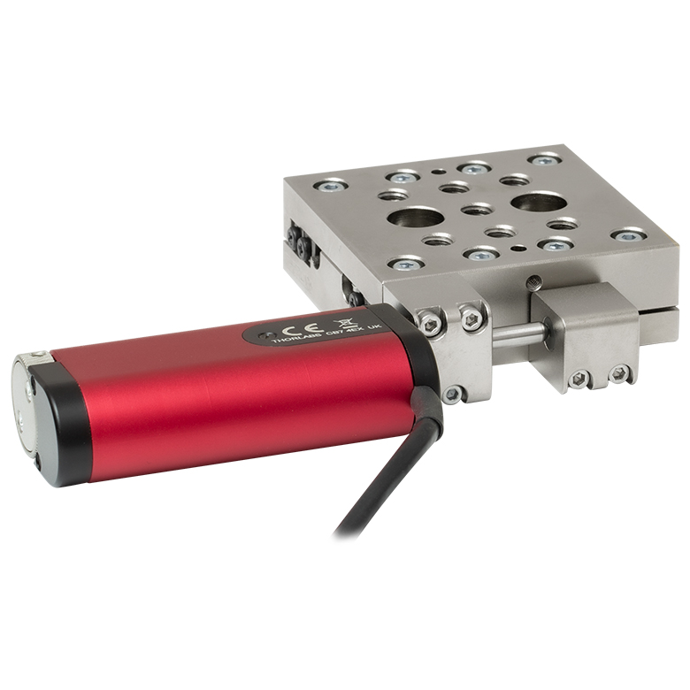
Figure 1.1 Translation + rotation stage created by mounting a UDX1 linear stage on a PDR1 rotation stage using the included dowel pins and mounting hardware.

Features
- Compact 20 mm Travel Stainless Steel Stage with Ultrasonic Piezo Drive
- Ideal for OEMs and Set-and-Hold Applications that Require Relative Positioning with High Speed (Up to 100 mm/s) and Force
- Top Plate Adapters Provide Alternative Mounting Hole Patterns
- Mounting Adapters Provide Flat Surfaces for Mounting Stages
- Right-Angle Bracket Adapter Allows Vertical Mounting and XYZ Configurations
- Requires an Ultrasonic Piezo Stage Controller (Sold Separately Below)
Thorlabs' ORIC® 20 mm Linear Travel Ultrasonic Piezoelectric Drive Stage provides fast and stable piezo-controlled linear motion in a compact, 15.0 mm thick package with no backlash. The UDX1(/M) single-axis stage features an optical encoder and supports closed-loop operation. The ultrasonic piezo drive mechanism of these stages is self-locking when the stage is at rest and no power is supplied to the piezo, making the stage ideal for set-and-hold applications that require nanometer resolution and long-term alignment stability. The resonant ultrasonic mechanism makes this stage ideal for applications requiring high speed and force, operating at typical speeds up to 100 mm/s while using less energy than our piezo inertia stages.
Load Mounting Options
The load can be secured to the stage's moving platform using 2-56 (M2 x 0.4) threaded holes or 8-32 (M4 x 0.7) threaded holes. Alternatively, the PD1T(/M) and PD1U(/M) adapter plates (sold separately below) provide alternative mounting hole patterns for the top plate of the stage. The load can be aligned using the array of Ø2 mm, 1.5 mm deep dowel pin holes; see the drawings below for details. Thorlabs offers replacement dowel pins in packs of 20 below. Ensure that the maximum insertion depth of these holes is not exceeded or else the stage may be damaged. For more information, please refer to the Specs tab or the support documents accessible through the red Support Docs icons ![]() )
)
Stage Mounting Options
Counterbores for mounting each stage are accessible when the moving plate is translated to the ends of the travel range. There are two mounting options: two 2-56 (M2 x 0.4) screws on the corners with 0.35 N·m recommended torque or 8-32 (M4 x 0.7) screws along opposing edges of the base with 0.55 N·m recommended torque.
The stages should be mounted on an even surface with a recommended flatness of ≤5 μm. If the stage is mounted on a surface with >5 µm flatness (as with most breadboards and optical tables), the mounting torque may need to be decreased in order for the velocity variation and pitch/yaw of the stage to meet specifications. If needed, the PD1B(/M), PD1B2(/M), and PD1B3(/M) mounting adapters provide a mounting surface with precise flatness to avoid warping the stage when mounting it to a table surface.
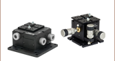
Two linear stages can be stacked on top of each other for an XY configuration for applications that require additional movement. The top and bottom of each stage feature four Ø2 mm holes for alignment via the included dowel pins, providing XY translation with orthogonality <5 mrad.
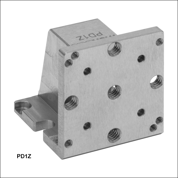
The PD1Z(/M) right-angle bracket adapter allows one single-axis stage to be mounted vertically on top of another stage for an XZ or XYZ configuration. Alternatively, the bracket and single-axis stage can be used with a PD1B(/M), PD1B2(/M) or PD3B(/M) adapter for a Z-configuration that can be directly mounted to an optical table or breadboard. Note that when the stage is mounted vertically, the load capacity is greatly reduced. Please see the Specs tab for more details.
Compatibility with Other ORIC Stages
These stages can be combined with an ORIC rotation stage for applications that require XY translation and rotation, an example of which is shown to the above and to the right. An XZ or XYZ configuration can be created by mounting one or more ORIC 20 mm linear stages onto the top platform of a PDXZ1(/M) piezo inertia stage with 4.5 mm of vertical motion. ORIC 20 mm linear stages can also be mounted on one of our ORIC 50 mm linear stages where greater travel range is necessary.
Required Controller
Our UDXC ultrasonic piezo controller is required to operate these stages. Note that the ultrasonic piezo drives cannot be driven using a standard piezo or piezo inertia controller. Please see below for more information on the UDXC controller.
Click to Enlarge
Figure 1.3 Simplified Illustration Showing the Operation of the Ultrasonic Piezo Drive
Figure 1.4 The ultrasonic drive cycle consists of an oscillation in the deformation of the piezo element.
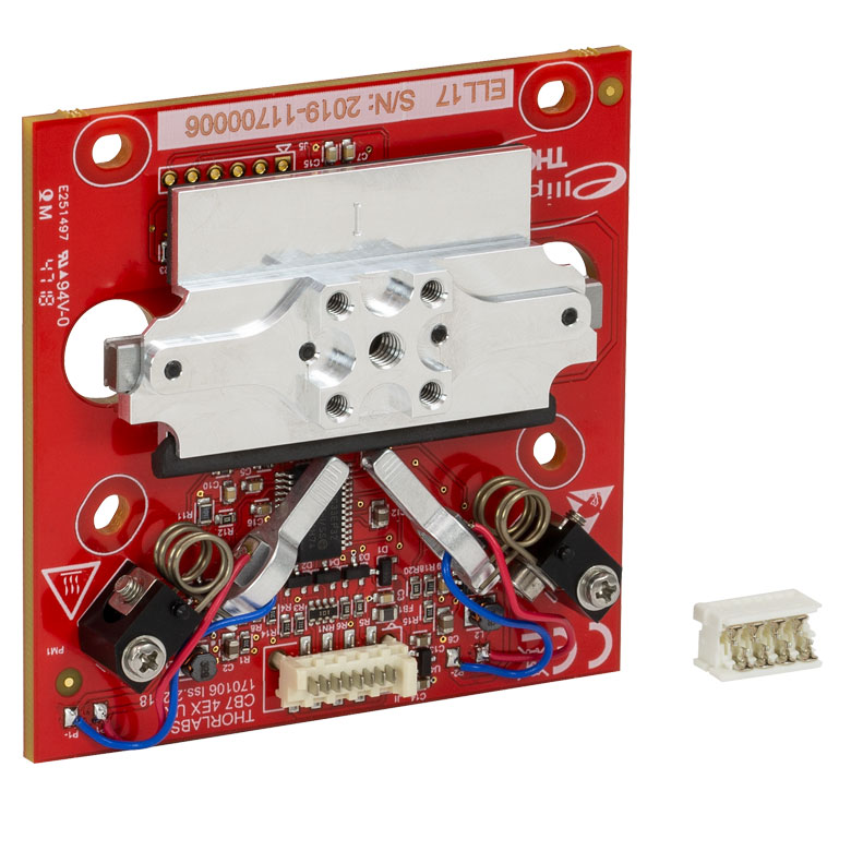
Ultrasonic Piezoelectric Motor
The ultrasonic piezo drive motor primarily consists of three main parts: a piezo motor, a friction component, and a slider (carriage plate). At point (A) shown in Figure 1.3 and the corresponding plot in Figure 1.4, the piezo motor is at the home position. One end of the motor is elastically fixed and the opposite end is in contact with the friction component. When the selected section of the motor is driven at its resonance, the non-fixed end traces an elliptical path in space. Point (B) shows the motor at the peak of its deformation; the motor has deformed to drive the friction component and slider during the upper half of the elliptical path. At point (C), the motor and friction component return to their home positions along the lower half of the elliptical path. The friction component will effectively detach from the slider so that the slider can retain its translated position. Figure 1.4 shows the deformation amplitude of the motor as a function of time through a cycle from (A) to (B) to (C).
With the resonant driving and the inertia of the slider, the slider will move forward slightly after each elliptical cycle. Repeated cycles will drive the slider forward. For backwards travel, the opposite section of the piezo motor is driven, deforming conversely such that it traces an ellipse in the opposite direction. Resonant vibration cycles result in high translation speed and force while driving at an ultrasonic frequency makes it low noise.
Due to a number of factors that include the application conditions, piezo hysteresis, component variance, and the axial load, the achieved step size will vary and is not repeatable. To help overcome this variance, an optical encoder provides external feedback to ensure repeatable motion.
| Table 2.1 UDX1(/M) Specificationsa,b | |||
|---|---|---|---|
| Stage Type | Single-Axis Stage with Closed-Loop Ultrasonic Piezo Drive | ||
| Travel | 20.0 mm | ||
| Optical Encoder Resolution | 12.5 nm | ||
| Bidirectional Repeatability | ±0.75 µm | ||
| Absolute Accuracy | ±2 µm | ||
| Minimum Incremental Motionc | 500 nm | ||
| Step Size Adjustabilityd | 10 nm to 10.00 mm | ||
| Settling Time (Typical) | 300 ms | ||
| Drive Frequency | 200 kHz | ||
| Speed (Typical Max, Continuous Stepping)c,e | 100 mm/s | ||
| Horizontal Load Capacity | 3 kg (6.6 lbs) | ||
| Vertical Load Capacityf | 150 g (5.3 oz) | ||
| Clamping / Holding Force | 4 N | ||
| Pitch / Yaw Deviation Over Travel Range | ≤200 µrad | ||
| XY Stacked Orthogonality | <5 mrad | ||
| Motor Type | Ultrasonic Piezoelectric Drive | ||
| Lifetimeg | ≥100 km | ||
| Piezo Specifications | |||
| Max Operating Voltage | 30 V | ||
| Capacitance | 90 nF | ||
| Physical Specifications | |||
| Operating Temperature | 10 to 40 °C | ||
| Connector Type | D-Sub 15-Pin Female | ||
| Cable Lengthh | 1.5 m (4.9 ft) | ||
| Top Plate Mounting Options |
Four 2-56 (M2 x 0.4) Threaded Holes, 3.5 mm Deep Six 8-32 (M4 x 0.7) Threaded Holes, 3.2 mm Deep Six Ø2 mm Dowel Pin Holes, 1.5 mm Deep PD1T(/M) and PD1U(/M) Adapters |
||
| Dimensions | 36.7 mm x 32.5 mm x 15.0 mm (1.44" x 1.28" x 0.59") |
||
| Weight (Including Cable) | 160 g (5.64 oz) | ||
| Required Controller (Sold Separately Below) |
UDXC | ||
| Table 2.2 UDXC Specificationsa | |||
|---|---|---|---|
| D-Sub Port | Number of Ports | One | |
| Voltage | 0 to 30 V | ||
| Frequency | 220 kHz Max | ||
| Max Current Limit | 8 A | ||
| Front USB | Type A, USB HID Host | ||
| Back USB | Type B, USB Device 2.0 | ||
| I/O Port | Voltage of Analog In/Out | -10 to 10 V, ±2% | |
| Voltage of Trigger In/Out | 0 to 5 V, TTL | ||
| Ethernet PC Communication | One RJ-45 Port | ||
| Dimensions (L x W x H) | 115.2 mm x 150.0 mm x 48.5 mm (4.54” x 5.91” x 1.91”) |
||
| Weight | 0.33 kg | ||
| Operating Temperature | 10 - 35 °C | ||
| DS12 Input Power | 100 - 240 VAC, 50 - 60 Hz | ||
| Input Power | 12 VDC, 3 A | ||
| Compatible Stages | UDX1(/M) | ||
UDX1(/M) Stage
Female 15-Pin D-Sub
| Pin(s) | Voltage Range | Name | Description |
|---|---|---|---|
| 1 | -7.5 to +12.5 V | Encoder_B_N | Encoder B- |
| 2 | -7.5 to +12.5 V | Encoder_B_P | Encoder B+ |
| 3 | 0 V | GND | Digital Ground |
| 4 | -7.5 to +12.5 V | Encoder_A_N | Encoder A- |
| 5 | -7.5 to +12.5 V | Encoder_A_P | Encoder A+ |
| 6 | - | - | Reserved |
| 7 | - | - | Reserved |
| 8 | +5 V | +5 V | 5 V Power |
| 9 | -7.5 to +12.5 V | Encoder_Z_N | Encoder Z- |
| 10 | -7.5 to +12.5 V | Encoder_Z_P | Encoder Z+ |
| 11 | 0 to +30 V | SigOut2 | Piezo Output 2 |
| 12 | 0 V | PGND | Power Ground |
| 13 | 0 to +30 V | SigOut1 | Piezo Output 1 |
| 14 | 5 V TTL | EEPROM | 1-Wire EEPROM |
| 15 | - | - | Reserved |
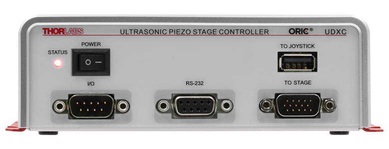
UDXC Front Panel
Male 15-Pin D-Sub
For UDX1(/M) Stages
For closed-loop operation, with a resolution down to 12.5 nm and speed up to 200 mm/s.
| Pin(s) | Voltage Range | Name | Description |
|---|---|---|---|
| 1 | -7.5 to +12.5 V | Encoder_B_N | Encoder B- |
| 2 | -7.5 to +12.5 V | Encoder_B_P | Encoder B+ |
| 3 | 0 V | GND | Digital Ground |
| 4 | -7.5 to +12.5 V | Encoder_A_N | Encoder A- |
| 5 | -7.5 to +12.5 V | Encoder_A_P | Encoder A+ |
| 6 | - | - | Reserved |
| 7 | - | - | Reserved |
| 8 | +5 V | +5 V | 5 V Power |
| 9 | -7.5 to +12.5 V | Encoder_Z_N | Encoder Z- |
| 10 | -7.5 to +12.5 V | Encoder_Z_P | Encoder Z+ |
| 11 | 0 to +30 V | SigOut2 | Piezo Output 2 |
| 12 | 0 V | PGND | Power Ground |
| 13 | 0 to +30 V | SigOut1 | Piezo Output 1 |
| 14 | 5 V TTL | EEPROM | 1-Wire EEPROM |
| 15 | - | - | Reserved |
I/O Port
An I/O cable is provided to breakout the Trigger In, Trigger Out, Analog In, and Analog Out pins to BNCs on included cable.
| Pin | Voltage Range | Name | Description |
|---|---|---|---|
| 1 | - | - | Reserved |
| 2 | 0 V | GND | Ground Pin |
| 3 | 0 to 5 V | Trigger In | Trigger to Update New Target Position |
| 4 | 0 V | GND | Ground Pin |
| 5 | -10 to +10 V | Analog In | Input as New Target Position |
| 6 | - | - | Reserved |
| 7 | 0 V | GND | Ground Pin |
| 8 | 0 to 5 V | Trigger Out | Trigger When Actual Position is on Target |
| 9 | -10 to +10 V | Analog Out | Output to Reflect the Actual Position |
RS-232
Connects to a computer for command-line control.
| Pin(s) | Voltage Range | Name | Description |
|---|---|---|---|
| 1 | - | N.C. | Not Connected |
| 2 | -15 to +15 V | TXD | Transmits Data |
| 3 | -15 to +15 V | RXD | Receives Data |
| 4 | - | N.C. | Not Connected |
| 5 | 0 V | GND | Ground Pin |
| 6,7,8,9 | - | N.C. | Not Connected |
USB (Type A)

Connects an HID MCMK3 joystick (available separately below) to control the stage movement by scrolling the wheel back and forth. When the device is set in open-loop operation, it will move a set number of pulses with each scroll, while in closed-loop operation it will move at a set step distance with each scroll.
UDXC Back Panel

RJ-45 Port
Connects the UDXC device to a router/switch for software control with a networked PC.
USB (Type B)

The USB port connects to a computer for software or command-line control.
Software
Kinesis Version 1.14.53
The Kinesis Software Package, which includes a GUI for control of Thorlabs' Kinesis system controllers.
Also Available:
- Communications Protocol

Figure 58A Kinesis GUI Screen
Thorlabs offers the Kinesis software package to drive our wide range of motion controllers. The software can be used to control devices in the Kinesis family, which covers a wide variety of motion controllers ranging from small, low-powered, single-channel drivers (such as the K-Cubes®) to high-power, multi-channel benchtop units and modular 19" rack nanopositioning systems (the MMR60x Rack System).
The Kinesis Software features .NET controls which can be used by 3rd party developers working in the latest C#, Visual Basic, LabVIEW™, or any .NET compatible languages to create custom applications. Low-level DLL libraries are included for applications not expected to use the .NET framework and APIs are included with each install. A Central Sequence Manager supports integration and synchronization of all Thorlabs motion control hardware.
By providing this common software platform, Thorlabs has ensured that users can mix and match any of our motion control devices in a single application, while only having to learn a single set of software tools. In this way, it is perfectly feasible to combine any of the controllers from single-axis to multi-axis systems and control all from a single, PC-based unified software interface.
The software package allows two methods of usage: graphical user interface (GUI) utilities for direct interaction with and control of the controllers 'out of the box', and a set of programming interfaces that allow custom-integrated positioning and alignment solutions to be easily programmed in the development language of choice.
Thorlabs' Kinesis software features new .NET controls which can be used by third-party developers working in the latest C#, Visual Basic, LabVIEW™, or any .NET compatible languages to create custom applications.
C#
This programming language is designed to allow multiple programming paradigms, or languages, to be used, thus allowing for complex problems to be solved in an easy or efficient manner. It encompasses typing, imperative, declarative, functional, generic, object-oriented, and component-oriented programming. By providing functionality with this common software platform, Thorlabs has ensured that users can easily mix and match any of the Kinesis controllers in a single application, while only having to learn a single set of software tools. In this way, it is perfectly feasible to combine any of the controllers from the low-powered, single-axis to the high-powered, multi-axis systems and control all from a single, PC-based unified software interface.
The Kinesis System Software allows two methods of usage: graphical user interface (GUI) utilities for direct interaction and control of the controllers 'out of the box', and a set of programming interfaces that allow custom-integrated positioning and alignment solutions to be easily programmed in the development language of choice.
For a collection of example projects that can be compiled and run to demonstrate the different ways in which developers can build on the Kinesis motion control libraries, click on the links below. Please note that a separate integrated development environment (IDE) (e.g., Microsoft Visual Studio) will be required to execute the Quick Start examples. The C# example projects can be executed using the included .NET controls in the Kinesis software package (see the Kinesis Software tab for details).
 |
Click Here for the Kinesis with C# Quick Start Guide Click Here for C# Example Projects Click Here for Quick Start Device Control Examples |
|
LabVIEW
LabVIEW can be used to communicate with any Kinesis-based controller via .NET controls. In LabVIEW, you build a user interface, known as a front panel, with a set of tools and objects and then add code using graphical representations of functions to control the front panel objects. The LabVIEW tutorial, provided below, provides some information on using the .NET controls to create control GUIs for Kinesis-driven devices within LabVIEW. It includes an overview with basic information about using controllers in LabVIEW and explains the setup procedure that needs to be completed before using a LabVIEW GUI to operate a device.
 |
Click Here to View the LabVIEW Guide Click Here to View the Kinesis with LabVIEW Overview Page |
|
| Posted Comments: | |
| No Comments Posted |
Motorized Linear Translation Stages
Thorlabs' motorized linear translation stages are offered in a range of maximum travel distances, from a stage with 20 µm of piezo translation to our 600 mm direct drive stage. Many of these stages can be assembled in multi-axis configurations, providing XY or XYZ translation. For fiber coupling applications, please see our multi-axis stages, which offer finer adjustment than our standard motorized translation stages. In addition to motorized linear translation stages, we offer motorized rotation stages and goniometers. We also offer manual translation stages.
Piezo Stages
These stages incorporate piezoelectric elements in a variety of drive mechanisms. ORIC® stages incorporate piezo inertia drives that use "stick-slip" friction properties to obtain extended travel ranges. Our Nanoflex™ translation stages use standard piezo chips along with manual actuators. Elliptec® stages use resonant piezo motors to push and pull the moving platform through resonant elliptical motion. Our LPS710E z-axis stage features a mechanically amplified piezo design and includes a matched controller.
| Piezoelectric Stages | ||||
|---|---|---|---|---|
| Product Family | ORIC® PDXZ1 Closed-Loop 4.5 mm Vertical Stage |
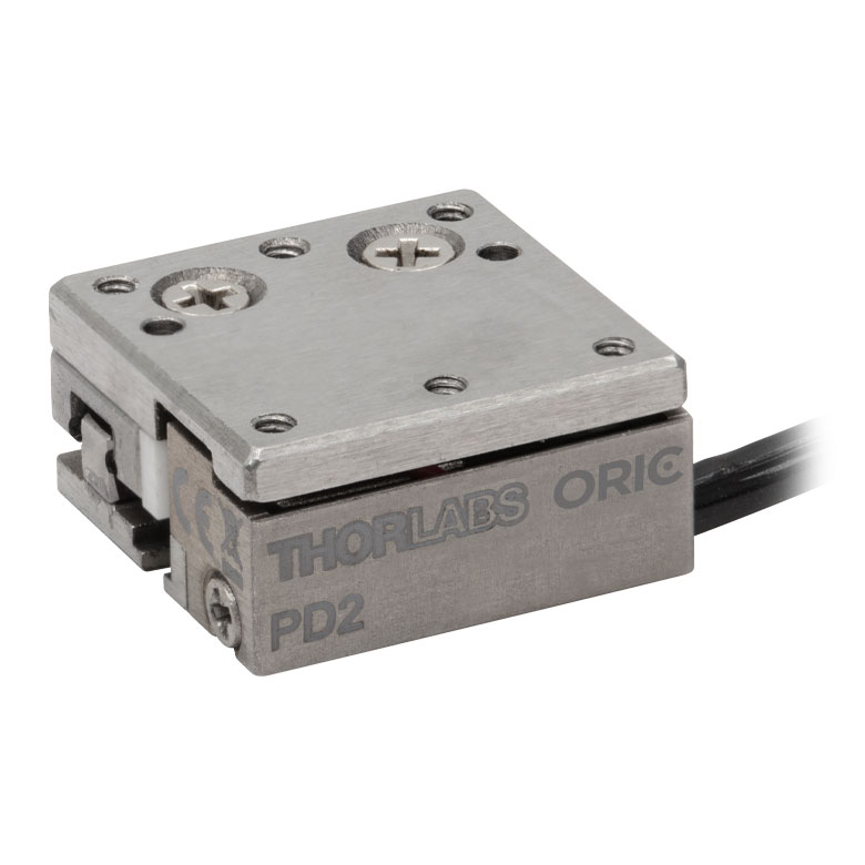
ORIC® PD2 Open-Loop 5 mm Stage |
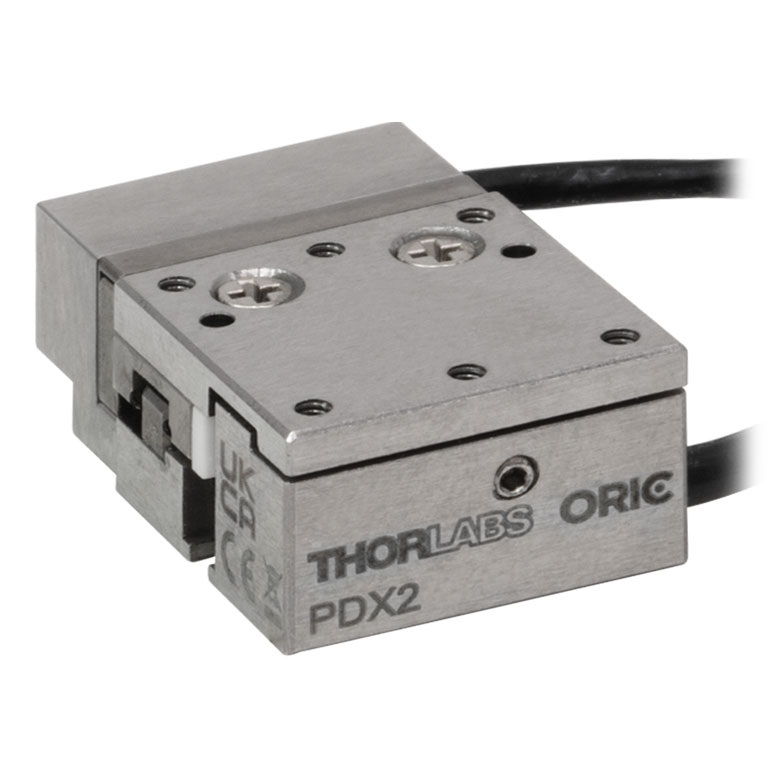
ORIC® PDX2 Closed-Loop 5 mm Stage |
ORIC® PDX4 Closed-Loop 12 mm Stage |
| Click Photo to Enlarge |
 |
 |
 |
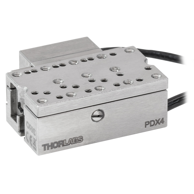 |
| Travel | 4.5 mm | 5 mm | 12 mm | |
| Speed | 1 mm/s (Typ.)a | 10 mm/s (Typ. Max)b | 8 mm/s (Typ.)c | 15 mm/s (Typ.)a,c |
| Drive Type | Piezoelectric Inertia Drive | |||
| Possible Axis Configurations | Z | X, XY, XYZ | ||
| Mounting Surface Size |
45.0 mm x 42.0 mm | 13.0 mm x 13.0 mm | 13.0 mm x 23.0 mm | |
| Additional Details | ||||
| Piezoelectric Stages | |||||||
|---|---|---|---|---|---|---|---|
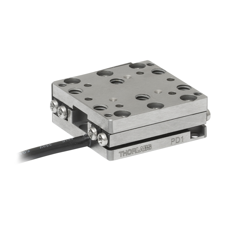
| Product Family | ORIC® PD1 Open-Loop 20 mm Stage |
ORIC® PD1D Open-Loop 20 mm Monolithic XY Stage |
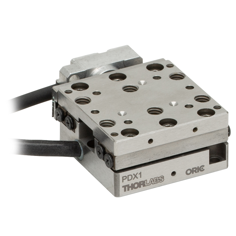
ORIC® PDX1 Closed-Loop 20 mm Stage |
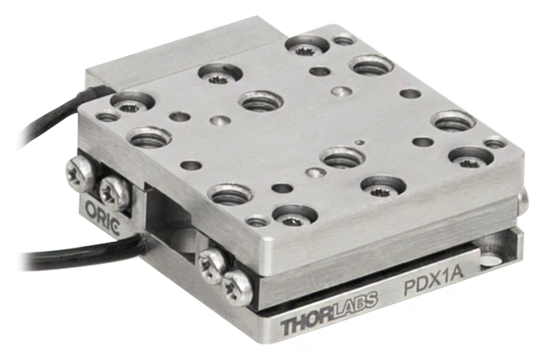
ORIC® PDX1A Closed-Loop 20 mm Stage Low-Profile |
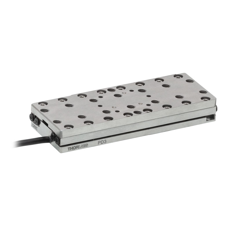
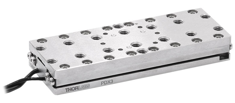
ORIC® PD3 Open-Loop 50 mm Stage |
ORIC® PDX3 Closed-Loop 50 mm Stage |
|
| Click Photo to Enlarge |
 |
 |
 |
 |
 |
 |
|
| Travel | 20 mm | 50 mm | |||||
| Speed | 3 mm/s (Typ. Max)a | 20 mm/s (Typ. Max)c | 10 mm/s (Typ.)b | 10 mm/sd | 10 mm/s (Typ. Max)b | ||
| Drive Type | Piezoelectric Inertia Drive | ||||||
| Possible Axis Configurations | X, XY, XYZ | XY, XYZ | X, XY, XYZ | X, XY, XYZ | X, XY, XYZ | X, XY, XYZ | |
| Mounting Surface Size |
30 mm x 30 mm | 80 mm x 30 mm | |||||
| Additional Details | |||||||
| Piezoelectric Stages | |||||||
|---|---|---|---|---|---|---|---|
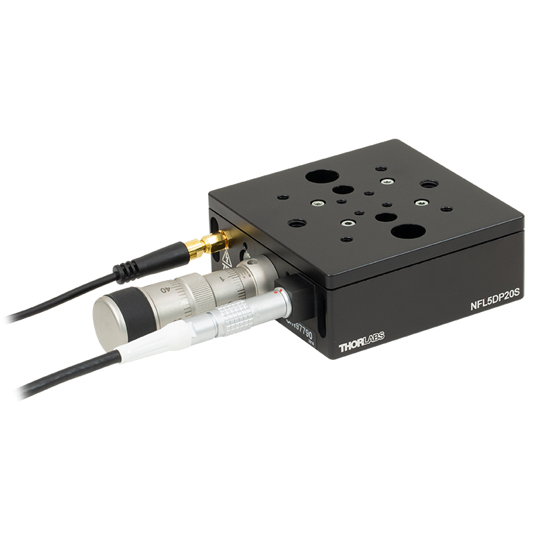
| Product Family | Nanoflex™ 20 µm Stage with 5 mm Actuator |
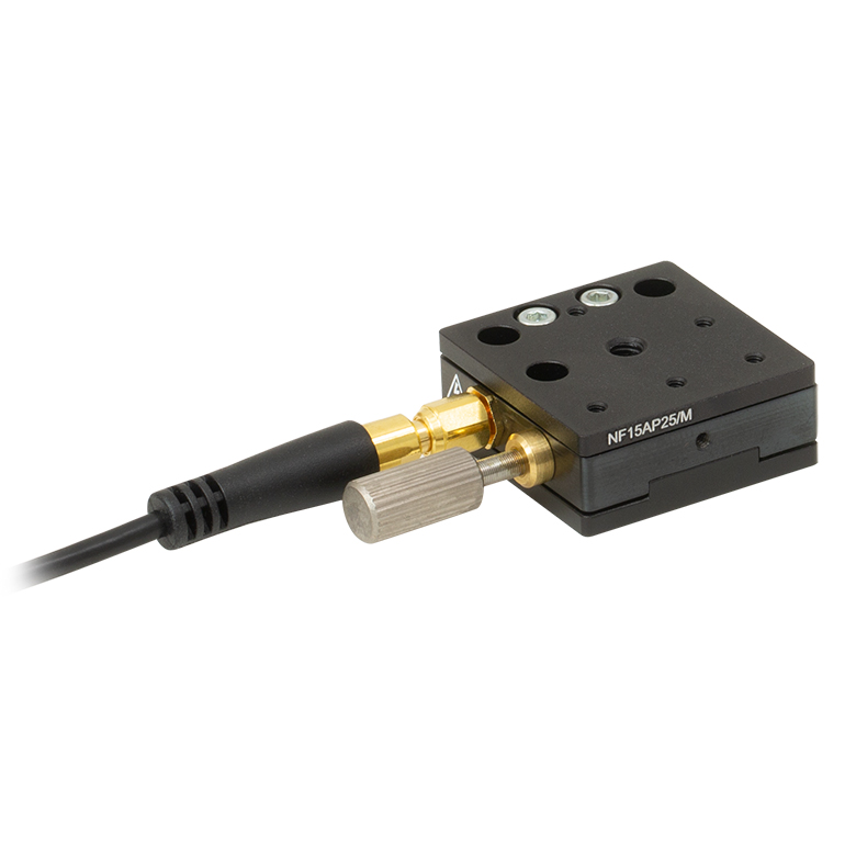
Nanoflex™ 25 µm Stage with 1.5 mm Actuator |
Compact Modular XRN25X 25 mm Stage |
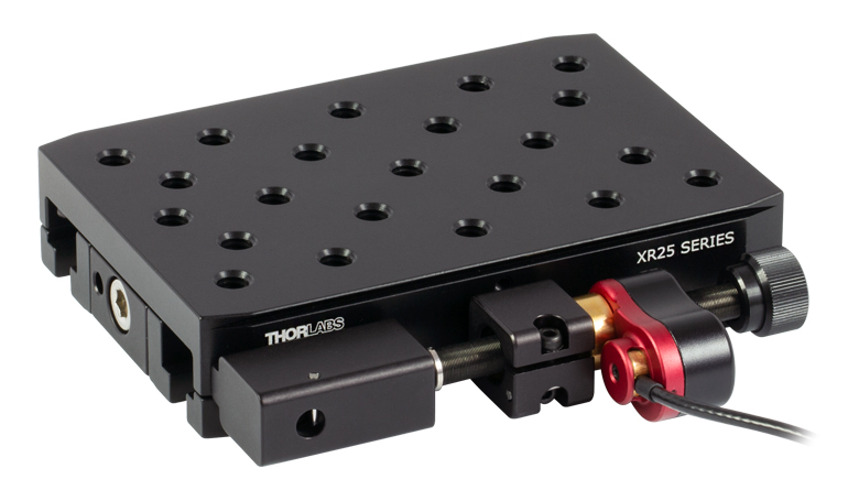
Modular XR25X 25 mm Stage |
Elliptec® 28 mm Stage | Elliptec® 60 mm Stage | LPS710E 1.1 mm Vertical Stage |
| Click Photo to Enlarge |
 |
 |
 |
 |
 |
 |
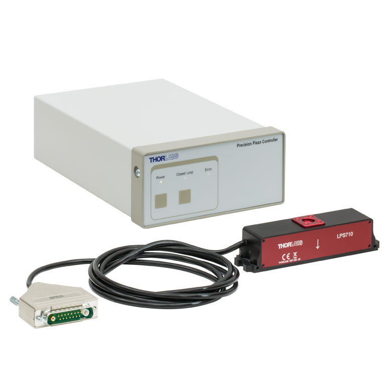 |
| Travel | 20 µm + 5 mm Manual | 25 µm + 1.5 mm Manual | 25 mm | 28 mm | 60.0 mm | 1.1 mm | |
| Maximum Velocity | - | ≤3.6 mm/mina | 180 mm/s | 90 mm/s | - | ||
| Drive Type | Piezo with Manual Actuator | Piezoelectric Inertia Drive | Resonant Piezoelectric Motor | Amplified Piezo | |||
| Possible Axis Configurations | X, XY, XYZ | X, XY, YZ, XZ, XYZ | X | Z | |||
| Mounting Surface Size | 75 mm x 75 mm | 30 mm x 30 mm | 85.0 mm x 50.7 mm | 110.0 mm x 75.7 mm | 15 mm x 15 mm | 21 mm x 21 mm | |
| Additional Details | |||||||
Stepper Motor Stages
These translation stages feature removable or integrated stepper motors and long travel ranges up to 300 mm. Many of these stages either have integrated multi-axis capability (PLSXY) or can be assembled into multi-axis configurations (PLSX, LNR Series, NRT Series, and LTS Series stages). The MLJ150 stage also offers high load capacity vertical translation.
| Stepper Motor Stages | |||||
|---|---|---|---|---|---|
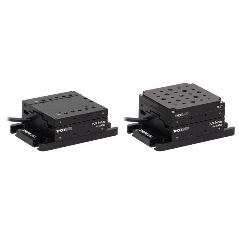
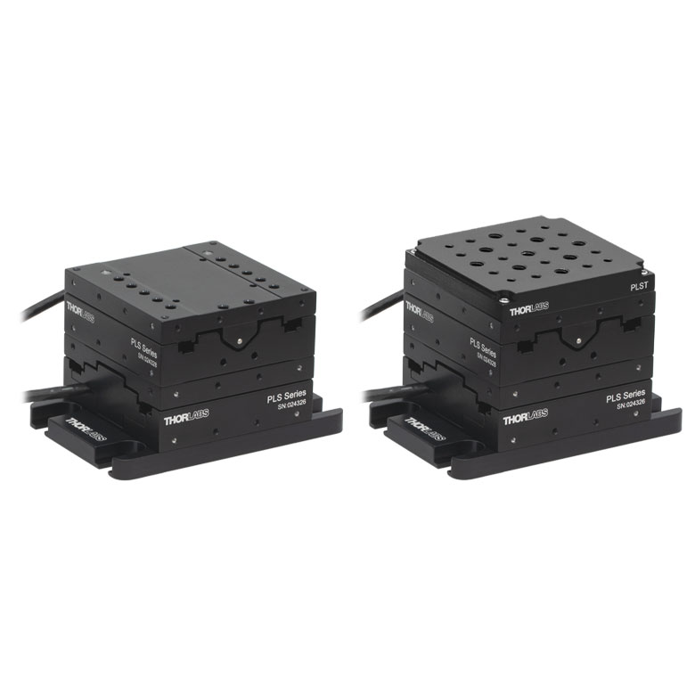
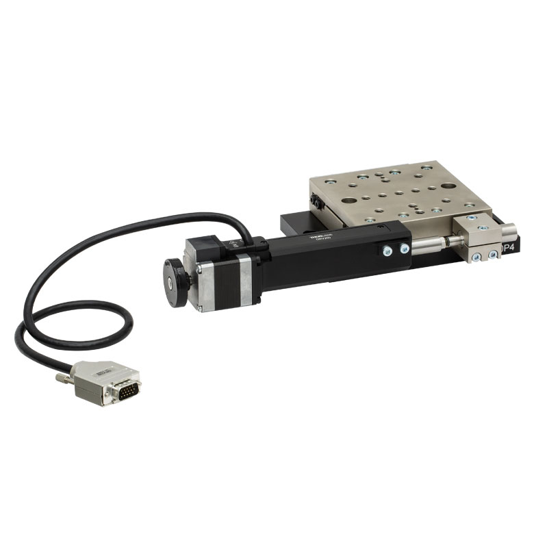
| Product Family | PLSX with and without PLST(/M) Top Plate 1" Stage |
PLSXY with and without PLST(/M) Top Plate 1" Stage |
LNR Series 25 mm Stage |
LNR Series 50 mm Stage |
|
| Click Photo to Enlarge |
 |
 |
 |
 |
|
| Travel | 1" | 25 mm | 50 mm | ||
| Maximum Velocity | 7.0 mm/s | 2.0 mm/s | 50 mm/s | ||
| Possible Axis Configurations |
X, XY | X, XY, XYZ | X, XY, XYZ | ||
| Mounting Surface Size |
3" x 3" | 60 mm x 60 mm | 100 mm x 100 mm | ||
| Additional Details | |||||
| Stepper Motor Stages | ||||||
|---|---|---|---|---|---|---|
| Product Family | NRT Series 100 mm Stage |
NRT Series 150 mm Stage |
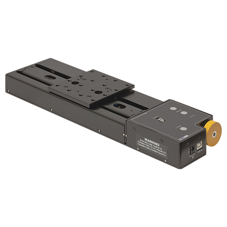
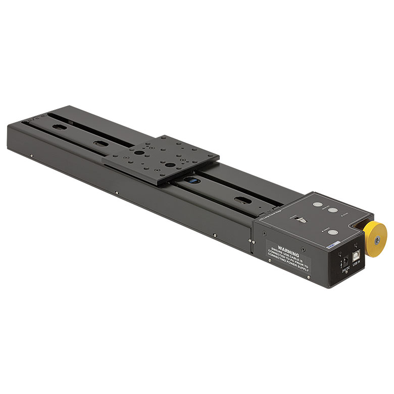
LTS Series 150 mm Stage |
LTS Series 300 mm Stage |
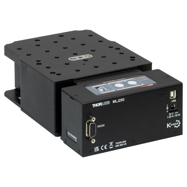
MLJ250 50 mm Vertical Stage |
|
| Click Photo to Enlarge |
 |
 |
 |
 |
 |
|
| Travel | 100 mm | 150 mm | 150 mm | 300 mm | 50 mm | |
| Maximum Velocity | 30 mm/s | 50 mm/s | 3.0 mm/s | |||
| Possible Axis Configurations |
X, XY, XYZ | X, XY, XYZ | Z | |||
| Mounting Surface Size |
84 mm x 84 mm | 100 mm x 90 mm | 148 mm x 131 mm | |||
| Additional Details | ||||||
DC Servo Motor Stages
Thorlabs offers linear translation stages with removable or integrated DC servo motors. These stages feature low profiles and many can be assembled in multi-axis configurations.
| DC Servo Motor Stages | ||||
|---|---|---|---|---|
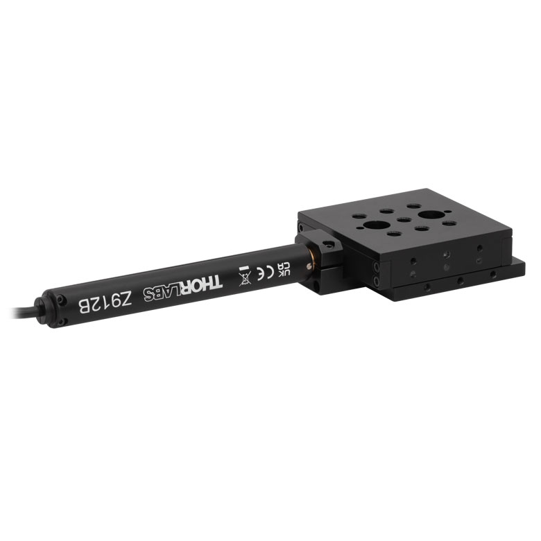
| Product Family | MT Series 12 mm Stages |
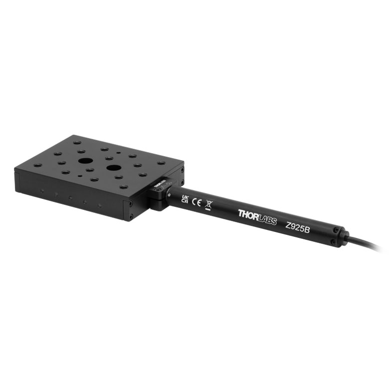
PT Series 25 mm Stages |
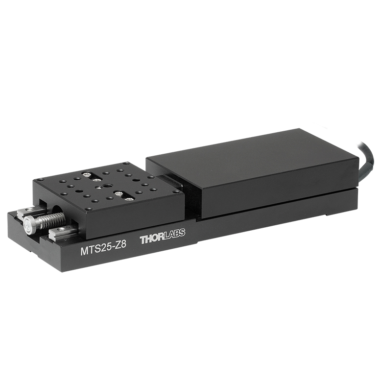
MTS Series 25 mm Stage |
MTS Series 50 mm Stage |
| Click Photo to Enlarge |
 |
 |
 |
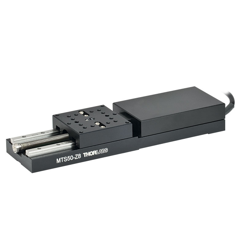 |
| Travel | 12 mm | 25 mm | 25 mm | 50 mm |
| Maximum Velocity | 2.6 mm/s | 2.4 mm/s | ||
| Possible Axis Configurations | X, XY, XYZ | X, XY, XYZ | ||
| Mounting Surface Size |
61 mm x 61 mm | 101.6 mm x 76.2 mm | 43 mm x 43 mm | |
| Additional Details | ||||
| DC Servo Motor Stages | ||||
|---|---|---|---|---|
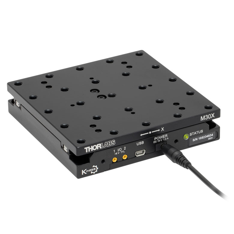
| Product Family | M30 Series 30 mm Stage |
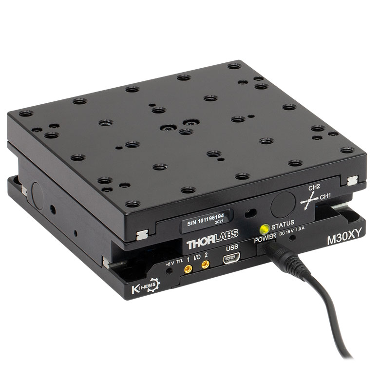
M30 Series 30 mm Monolithic XY Stage |
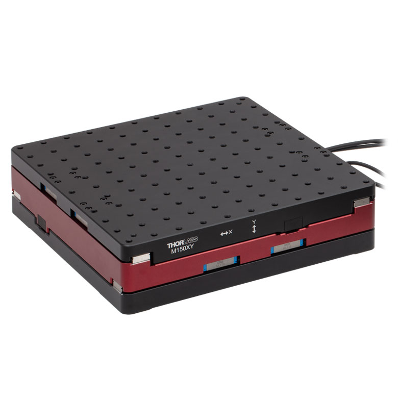
M150 Series 150 mm XY Stage |
KVS30 30 mm Vertical Stage |
| Click Photo to Enlarge |
 |
 |
 |
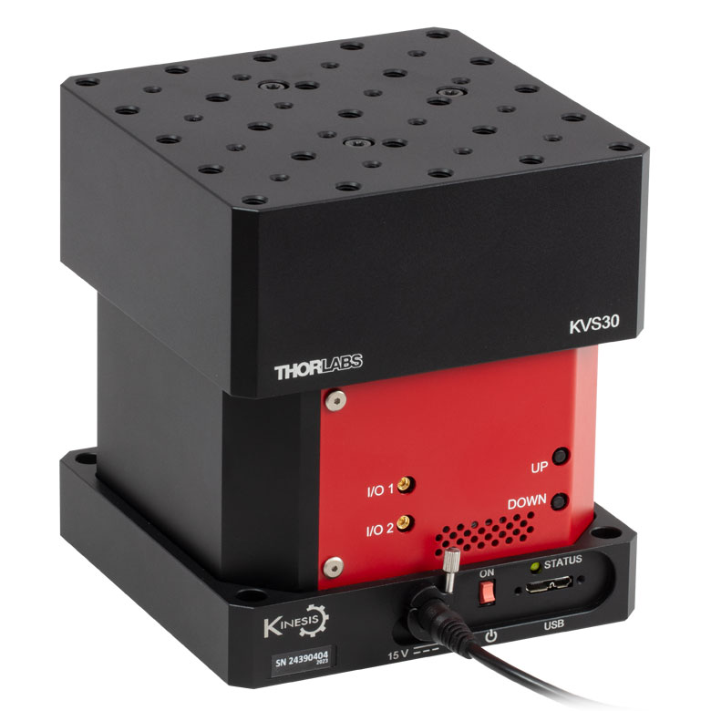 |
| Travel | 30 mm | 150 mm | 30 mm | |
| Maximum Velocity | 2.4 mm/s | X-Axis: 170 mm/s Y-Axis: 230 mm/s |
8.0 mm/s | |
| Possible Axis Configurations | X, Z | XY, XZ | XY | Z |
| Mounting Surface Size |
115 mm x 115 mm | 272.4 mm x 272.4 mm | 116.2 mm x 116.2 mm | |
| Additional Details | ||||
Direct Drive Stages
These low-profile stages feature integrated brushless DC servo motors for high speed translation with zero backlash. When no power is applied, the platforms of these stages have very little inertia and are virtually free running. Hence these stages may not be suitable for applications where the stage's platform needs to remain in a set position when the power is off. We do not recommend mounting these stages vertically.
| Direct Drive Stages | |||||
|---|---|---|---|---|---|
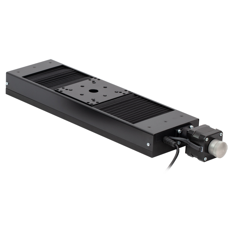
| Product Family | DDS Series 50 mm Stage |
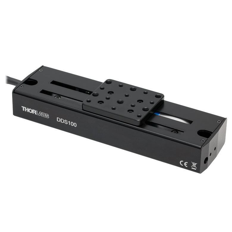
DDS Series 100 mm Stage |
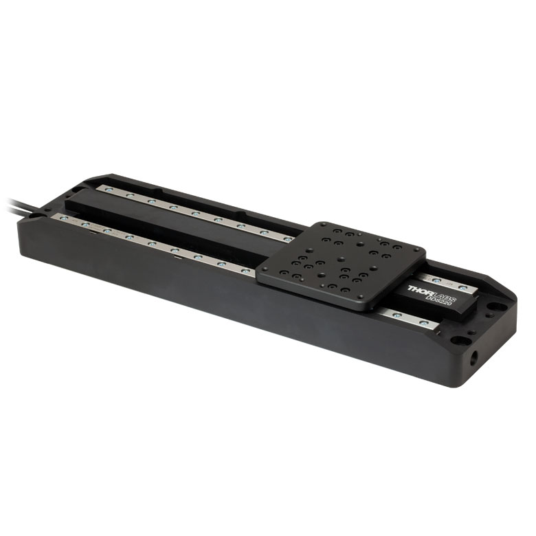
DDS Series 220 mm Stage |
DDS Series 300 mm Stage |
DDS Series 600 mm Stage |
| Click Photo to Enlarge |
 |
 |
 |
 |
 |
| Travel | 50 mm | 100 mm | 220 mm | 300 mm | 600 mm |
| Maximum Velocity | 500 mm/s | 300 mm/s | 400 mm/s | 400 mm/s | |
| Possible Axis Configurations | X, XY | X, XY | X | X | |
| Mounting Surface Size | 60 mm x 52 mm | 88 mm x 88 mm | 120 mm x 120 mm | ||
| Additional Details | |||||

 Zoom
ZoomIncludes:
- Linear Stage with Integrated Cable, D-Sub Female Connector
- Two 2-56 (M2 x 0.4) Cap Screws, 5/32" (4 mm) Long
- Two 8-32 (M4 x 0.7) Cap Screws, 3/8" (10 mm) Long
- Three M1.4 Cap Screws, 4 mm Long
- Two Ø2 mm Dowel Pins, 3 mm Long
- Shipping Plate
- Individual Test Data Certificate
- Closed-Loop Operation
- Optical Encoder Provides Resolution Down to 12.5 nm
- Moves at a Speed of Up to 100 mm/s
- <5 mrad Orthogonality for Two Stages Stacked in an XY Configuration
- Integrated 1.5 m (4.9 ft) Cable with 15-Pin D-Sub Female Connector
- Requires the UDXC Ultrasonic Piezo Controller (Sold Separately Below)
- Each Stage Individually Tested and Shipped with Test Data Certificate
This ORIC® ultrasonic piezo stage with an optical encoder operates in closed-loop mode, can support loads up to 3 kg, and can achieve typical speeds up to 100 mm/s with no backlash. The resonant ultrasonic mechanism makes this stage ideal for applications where high speed, acceleration, and force are required. Closed-loop operation also makes the stage suitable for applications where repeatable positioning is needed. See the Specs tab for detailed specifications.
Click for Details
Figure G1.1 UDX1(/M) Top Plate Schematic. Dimensions for the metric version of the stage are given in parentheses.
After each stage is manufactured, the pitch and yaw deviation of the stage are tested over the travel range. This ensures that each stage meets the stated specifications over the full translation range of the stage. A summary of the test results is provided on a data sheet that ships with each stage. A sample data sheet can be viewed here.
The stage should be placed on a surface with flatness ≤5 µm. If needed, the PD1B(/M), PD1B2(/M), or PD1B3(/M) mounting bases (sold separately below) will provide a flat surface for the stage to reduce warping of the stage that can impact performance. Along with this, we also offer alternative top plate adapters and a right-angle bracket adapter.
Each stage has an integrated 1.5 m cable. Please note that, due to the capacitance of the cables, the PDXCE extension cable is not compatible; do not use cables longer than 1.5 m in total.
Compatible Controllers: The UDX1(/M) stage is only compatible with the UDXC controller (sold separately below).
Note: During operation, the stage might generate low frequency noise due to friction between ceramic bar and tip and may generate some heat. This is normal behavior in the performance of the device and does not indicate a fault condition.

 Zoom
Zoom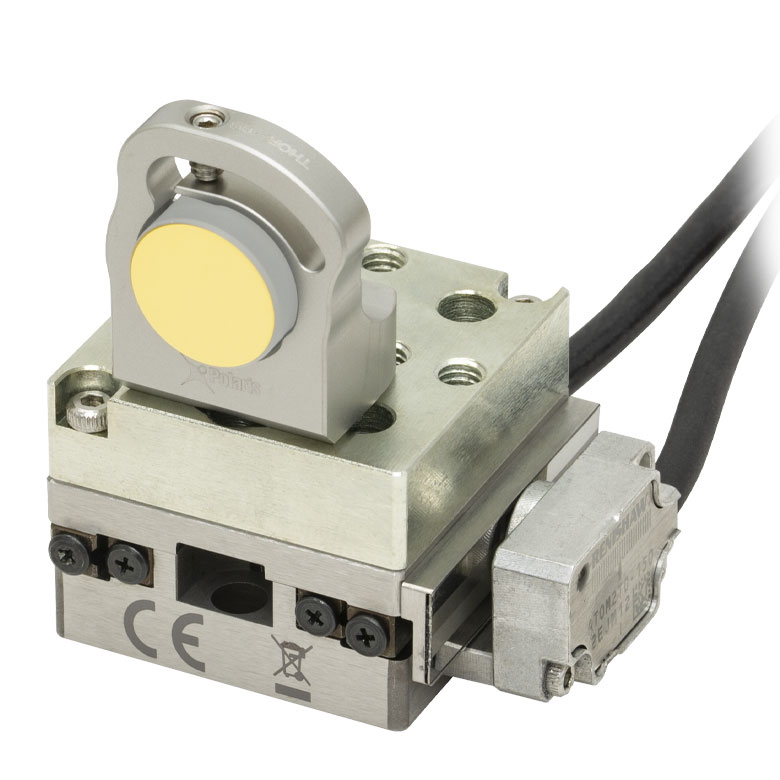
Click to Enlarge
Figure 804C PF05-03-M01 Mirror in POLARIS-B05S Fixed Optic Mount on PD1U Adapter Plate with PDX1 Stage
Click for Details
Figure 804A PD1T and PD1T/M Adapter Plate Schematics

Click for Details
Figure 804B PD1U Adapter Plate Schematic. Dimensions for the metric adapter plate are given in parentheses.
- Provide Different Mounting Hole Patterns
- Match 30 mm x 30 mm Footprint of Piezo Stage
- Each Adapter Includes Two 2-56 (M2 x 0.4) Mounting Screws and Two Ø2 mm Dowel Pins
These adapter plates provide alternative mounting holes for the stages above. Each adapter matches the footprint of the stage and can be secured to the top or bottom of the stage using the two included 2-56 (M2 x 0.4) cap screws in the mounting counterbores near the corners.
The PD1T imperial adapter plate features a central 8-32 tapped hole and sixteen 4-40 tapped holes, four of which are spaced for 16 mm cage systems. The metric version features a central M4 x 0.7 tapped hole, ten M2 x 0.4 mounting taps, four
The PD1U imperial adapter plate features four 6-32 and four 8-32 tapped holes in a cross pattern; the metric version features eight M4 x 0.7 tapped holes in the same layout. The bottom surface features five #8 (M4) counterbores, as well as four Ø2 mm dowel pin holes for alignment. See Figure 804B for more details.

 Zoom
Zoom
Click to Enlarge
Figure G3.3 UDX1 Stage Mounted to PD1B Adapter
Click for Details
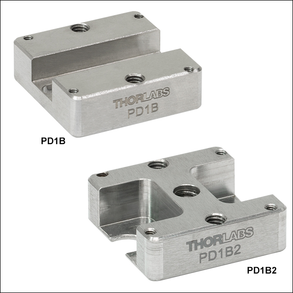
Figure G3.2 PD1B2(/M) Mounting Adapter Schematic. Dimensions for the metric stage are given in parentheses.
Click for Details
Figure G3.1 PD1B(/M) Mounting Adapter Schematic. Dimensions for the metric stage are given in parentheses.
- Provide Flat Surface for Mounting PD1(/M), PD1V(/M), PDX1(/M), PDX1A(/M), PDX1AV(/M), or UDX1(/M) Stages
- Two Versions Available:
- PD1B(/M): #8 (M4) Mounting Slot
- PD1B2(/M): 1/4" (M6) Mounting Slots and 1/4"-20 (M6 x 1.0) Threaded Mounting Hole
- Reduces Stage Warping When Mounting to Table or Breadboard
These adapters provide a flat surface for mounting the stages above. The PD1B(/M) adapter features a #8 (M4) mounting slot and the PD1B2(/M) adapter features 1/4" (M6) mounting slots and a 1/4"-20 (M6 x 1.0) threaded mounting hole. If the stage is mounted on a surface with >5 µm flatness (as with most breadboards and optical tables), the velocity variation and pitch/yaw of the stage may suffer due to the stage warping. Mounting the stage on these adapters drastically reduces the amount the stage warps when mounted on a table or breadboard with insufficient flatness.
The stage can be mounted to the adapter using two 2-56 (M2 x 0.4) screws near the corners with a maximum of 0.35 N·m torque. Alternatively, two 8-32 (M4 x 0.7) screws can be used on either end of the stage with up to 0.55 N·m torque. To mount the PD1B(/M) to a breadboard, two SH8S025 (SH4MS06) 8-32 (M4 x 0.7) cap screws and two W8S038 #8 (M4) washers can be used. To mount the PD1B2(/M) to a breadboard, two SH25S038 (SH6MS10) 1/4"-20 (M6 x 1.0) and two W25S050 1/4" (M6) washers can be used.

 Zoom
Zoom
Click for Details
Figure G4.2 Mechanical Drawing for the PD1B3(/M) Adapter Plate. See Table G4.3 for descriptions of the hole labels. Dimensions for the metric version of the adapter plate are given in parentheses.
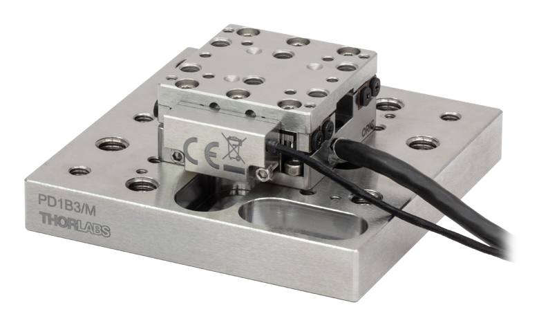
Click to Enlarge
Figure G4.1 UDX1/M Stage Mounted to PD1B3/M Adapter
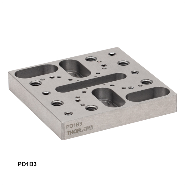
- Provide Flat Surface for Mounting ORIC Stages
- Passivated Stainless Steel Construction
- Reduces Stage Warping When Mounting to Table or Breadboard
- Dimensions (L x W x H): (65.0 mm x 65.0 mm x 10.0 mm)
Thorlabs' PD1B3(/M) Universal Adapter Plate provides a flat surface (flatness ≤5 µm) for mounting any of the ORIC piezo stages. Mounting holes are labeled in Figure G4.2 corresponding to Table G4.3. The four 4-40 threaded holes are 30 mm cage system compatible, and two 1/4"-20 (M6 x 1.0) screws are included for mounting to breadboards.
If the stage is mounted on a surface with >5 µm flatness (as with most breadboards and optical tables), the velocity variation and pitch/yaw of the stage may suffer due to the stage warping. Mounting the stage on the adapter drastically reduces the amount the stage warps when mounted on a table or breadboard with insufficient flatness.
| Table G4.3 Mounting Holes | ||||
|---|---|---|---|---|
| Labela | Holes/Slots Patternb | Spacingb (Stage Compatibility) | Threading Depth | Places |
| A | 1/4"-20 (M6 x 1.0) | 1" x 2" (25 x 50 mm) | Through | 6 |
| B | Ø2 mm Dowel Pin Holes |
16 x 16 mm (Item #s PDXZ1(/M), PD1(/M), PD1V(/M), PD1D(/M), PDX1(/M), PDX1A(/M), PDX1AV(/M), PD3(/M), PDX3(/M), PDR1C(/M), UDX1(/M)) | 1.5 mm | 4 |
| C | 4-40 | 30 x 30 mm (Item #s PDR1(/M), PDR1V(/M)) | 3.5 mm | 4 |
| D | 1/4" (M6) Counterbored Slot | 1" to 2" (25 to 50 mm) | N/A | 4 |
| E | 00-90 (M1.2 x 0.25) | 10 x 10 mm (Item #s PD2(/M), PDX2(/M), PDX4(/M)) | 3 mm | 4 |
| F | #8 (M4) Counterbored Slot | 1.25" (31.25 mm) | N/A | 1 |
| G | 2-56 (M2 x 0.4) | 27.0 x 23.4 mm (Item #s PDXZ1(/M), PD1(/M), PD1V(/M), PD1D(/M), PDX1(/M), PDX1A(/M), PDX1AV(/M), PDR1C(/M), UDX1(/M)) / 40.8 x 30 mm |
7 mm | 8 |
| H | 8-32 (M4 x 0.7) | 1" (25 mm) (Item # UDX1(/M)) 2" (50 mm) (Item #s PD3(/M), PDX3(/M)) / 2" x 2" (50 x 50 mm) (Item # PDXR1(/M)) |
7.8 mm | 4 |

 Zoom
Zoom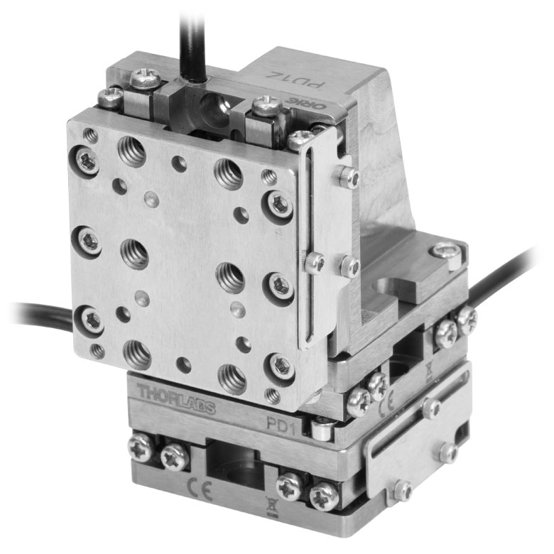
Click to Enlarge
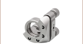
Figure 805B Three PD1(/M) Stages can be mounted in an XYZ configuration using the PD1Z(/M) adapter.
Click for Details
Figure 805A Schematic of Right-Angle Bracket's Vertical Face. Dimensions for the metric bracket are given in parentheses.
- Connects Single-Axis Stages for 2-Axis or 3-Axis Configuration
- Mounts Stage at 90° for Vertical or Horizontal Translation
- Two 2-56 (M2 x 0.4) Mounting Screws Included
The PD1Z(/M) right-angle bracket allows the user to mount the single-axis stages above at 90° for Z-axis, XZ, or XYZ applications. The bracket can be secured to the top plate of a stage using two 2-56 (M2 x 0.4) cap screws in the mounting counterbores near the corners. The vertical stage can be mounted on the bracket using the two included 2-56
The piezo stage can be mounted on the right-angle bracket for either vertical or horizontal translation. Using the #8 (M4) counterbores on the bracket, the single-axis stage can be secured to a PD1B(/M), PD1B2(/M), or PD3B(/M) adapter for a Z-axis configuration that can be mounted to an optical table or breadboard.
Note that in an XYZ configuration, the locking plate of the bottom stage may interfere with the translation range of the vertical stage. Simply remove the locking plate to achieve the full range of translation in all three dimensions.
Note: When mounted vertically, long term usage (>3 billion steps) may cause creep of the rails, leading to decreased travel range. To avoid this, return the stage to a horizontal position and run it back and forth over the full range several times after approximately 1 billion steps in a vertical orientation. Mounting the PD1D(/M) monolithic stage vertically is not recommended because the rails for one axis will experience a lateral force that may influence the angular error and even reduce the lifespan of the rail.

 Zoom
Zoom
Click for Details
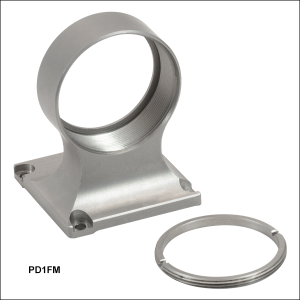
Figure 802A Mounting Holes on the PD1FM Optic Mount
- Compatible with All PD1 Series and UDX1(/M) 20 mm Piezo Stages
- Vertically Centers an Optic Along the 30 mm Cage System Optical Axis when Used with the PD1(/M) or PD1V(/M) Stage and the XPCM1(/M) Cage System Mount
- Mount Optic at 0 or 90° to the Stage's Translation Axis
- SM1-Threaded Optic Bore with Included POLARIS-SM1RR Retaining Ring
- Mounts Ø1" Optics up to 0.28" (7.1 mm) Thick
The PD1FM Fixed Optic Mount is designed to mount a Ø1" optic along the optical axis of a 30 mm cage system when used with a PD1(/M) or PD1V(/M) stage and XPCM1(/M) mount.
Note that the XPCM1(/M) cage mount and PD1FM Ø1" optic mount can be used together with the PDX1(/M) and UDX1(/M) stages but the optic will not be centered along the cage system's optical axis. The PD1D(/M) XY stage cannot be used with the cage mount and Ø1" optic mount at the same time. The PD1FM optic mount can be used with all PD1 series and UDX1(/M) stages outside of a cage system.
The base plate has two pairs of #2 (M2) counterbored mounting holes and four 0.07" (1.8 mm) deep alignment pin holes for mounting at 0 or 90° to the translation axis of the stage, enabling z- or x-axis adjustment; two Ø2 mm alignment pins are included with the PD1FM mount. When incorporated into a 30 mm cage system using a PD1(/M) stage mounted on the stage to cage mount above, the full 20 mm translation range of the PD1(/M) or PD1V(/M) stage is achievable in the z direction while the cutouts in the sides of the PD1FM mount provide clearance for ±3 mm of movement along the X-axis.
The optic bore has 0.36" (9.1 mm) deep SM1 (1.035"-40) threads and can hold optics up to 0.28" (7.1 mm) thick when used with the included POLARIS-SM1RR retaining ring.

 Zoom
Zoom
Click for Details
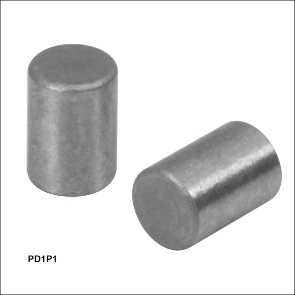
Figure 753A PD1P1 Dowel Pins fit into the mounting holes of most ORIC® Stages, as shown here in the PD1 Stage.
- Ø2 mm, 3 mm Long Dowel Pins
- Corrosion-Resistant Stainless Steel
- Sold in Packs of 20
The PD1P1 Dowel Pins are 2 mm in diameter and are 3 mm long. They serve as replacements for the dowel pins that are included with Thorlabs' 4.5 mm Vertical, 20 mm, 50 mm, Rotating, and Vacuum-Compatible ORIC® Stages. Composed of stainless steel, the dowel pins are corrosion-resistant.
The dowel pins are sold in packs of 20.

 Zoom
Zoom| Key Specificationsa | ||
|---|---|---|
| Performance Specificationsa | ||
| D-Sub Port | Number of Ports | One |
| Voltage | 0 to 30 V | |
| Frequency | 220 kHz Max | |
| Max Current Limit | 8 A | |
| Front USB | Type A, USB HID Host | |
| Back USB | Type B, USB Device 2.0 | |
| I/O Port | Voltage of Analog In/Out | -10 to 10 V, ±2% |
| Voltage of Trigger In/Out | 0 to 5 V, TTL | |
| Ethernet PC Communication | One RJ-45 Port | |
| Dimensions (L x W x H) | 115.2 mm x 150.0 mm x 48.5 mm (4.54” x 5.91” x 1.91”) |
|
| Weight | 0.33 kg | |
| Input Power | 12 VDC, 3 A | |
- For complete specifications, please see the manual by clicking the red Docs icon (
 ) below.
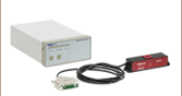
- Controller for ORIC Ultrasonic Piezoelectric Drive Linear Stages
- Compact Design and PC Control with Kinesis® Software
- Supports Closed-Loop Operation
- Energy Efficient Switch Amplifier Circuit Outputs Peak Current of 10 A
- Configurable High Speed Communication Interfaces: USB 2.0, Gigabit Ethernet, Digital I/O, Analog I/O
- Max Drive Frequency of 220 kHz
The UDXC compact controller is designed for our UDX1(/M) ORIC ultrasonic piezoelectric drive linear stage. It features one channel that supports closed-loop stage control using a 15-pin D-Sub output.
The UDXC controller is connected to PC by either the USB or ethernet ports on the back panel of the controller. All the operating parameters and operations, such as performing homing operation and parameter optimization, are controlled by PC with the Kinesis® software (available for download in the Kinesis Software tab). Settings such as trigger modes and movement parameters can be configured for operations such as raster scans. Please see the user manual for details. Command-line control is also possible through the USB and RS-232 ports.
The UDXC control unit is powered by the included DS12 12 VDC power adapter, which operates at an input voltage of 100 - 240 VAC and ships with a region-specific AC cable. For all applications, use an IEC320 compatible power cord fitted with a plug appropriate for your particular power socket. Make sure that the line voltage rating marked on the power adapter agrees with your local power supply.

 Zoom
Zoom- Utilizes Standard USB HID Protocol
- Knobs Provide Hand-Operated Control for up to Three Axes
- Top-Located Speed Dial for Sensitivity Adjustment
The MCMK3 Joystick is a hand-operated, 3-knob box with an attached USB cable. Each of the three side faces of the joystick include a rotating knob and a push-button LED switch. When the HID Joystick is connected to the USB connector on the front panel of the UDXC controller, the user can control the stage with the joystick. The move speed and step size can be set by adjusting the jog parameters in the settings panel of the Kinesis GUI. This joystick is a USB HID device and is powered through the USB cable.
The MCMK3 joystick can be used with any device that uses the HID class; for more information, see the complete web presentation. For a test utility to aid in troubleshooting and testing the HID reporting of the joystick, see the USB HID Joystick Software page.