 Products Home / Imaging Components / Microscopy Illumination Sources / Collimated LED Light Sources for Microscopy
Collimated LED Light Sources for Microscopy
- UV, Visible, and IR LEDs
- Mounted LED with Adjustable Collimation Optic
- Compatible with Epi-Illumination Port on Olympus, Leica, Nikon,
and Zeiss Microscopes
M625L4-C1
For Olympus
BX/IX Microscopes
M590L4-C5
For Nikon Eclipse
Microscopes
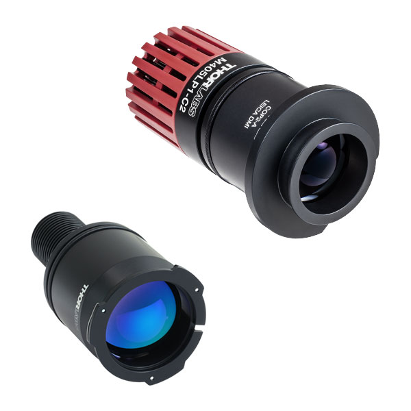
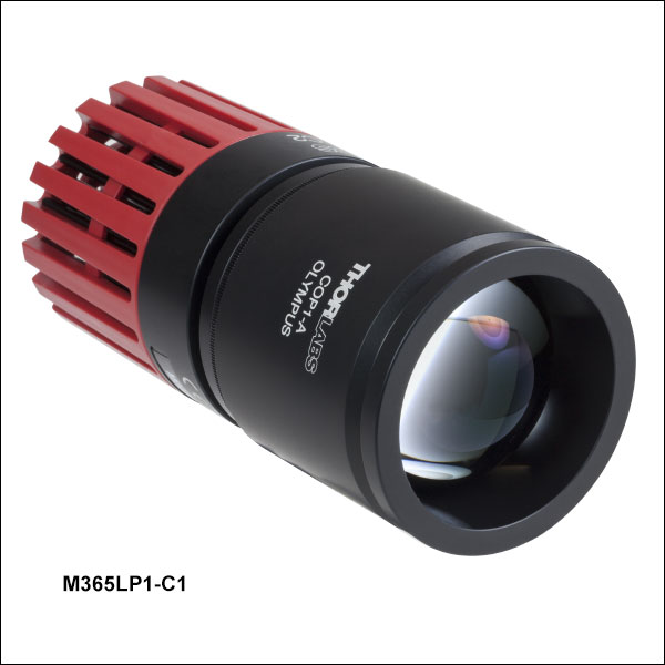
M405LP1-C2
For Leica DMI
Microscopes
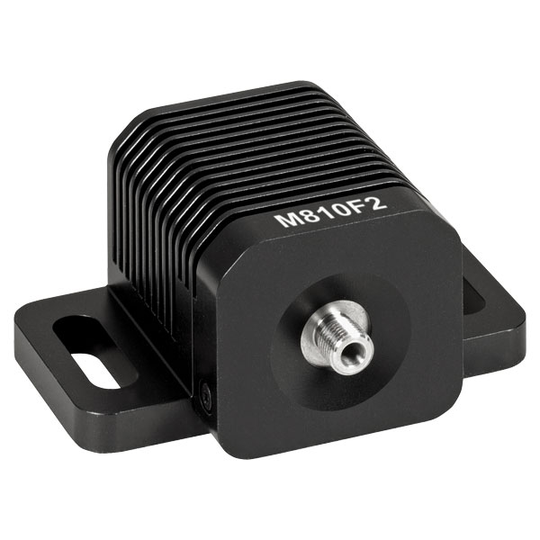
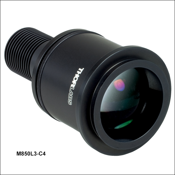
M850L3-C4
For Zeiss Axioskop
Microscopes
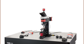
M505L4-C1 Used
as a Light Source for
an Olympus IX71


Please Wait
| Quick Links |
|---|
| LEDs for Olympus Microscopes |
| LEDs for Leica Microscopes |
| LEDs for Zeiss Microscopes |
| LEDs for Nikon Microscopes |
| Mounted LED Mating Connector |
Features
- Illumination Source for Microscope Epi-Illumination Ports, Projectors, and Custom Imaging Systems
- Optimized Thermal Management Provides Output Intensity Stability
- Adjustable Aspheric Collimation Optic with Low f/# (Approximately 0.8)
- Integrated Identification Chip (EEPROM) Stores LED Operating Parameters
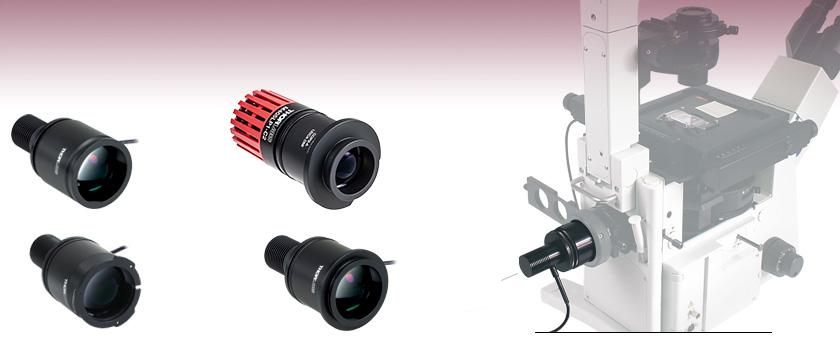
- Higher Power LEDs Mounted to Larger Heat Sink with Ø57.0 mm Plastic Housing (See the Tables Below for Details)
- 4-Pin Female Mating Connector for Custom Power Supplies can be Purchased Separately
- Custom Adapters Available - Contact Tech Support for Details
Thorlabs' collimated LED assemblies can be easily connected to standard and epi-illumination ports on most readily available commercial microscopes, including Olympus, Leica, Nikon, and Zeiss. Each collimated LED consists of a mounted LED and a lamphouse-port-compatible housing that contains an AR-coated aspheric collimation optic (see the Specs tab for details). If the wavelength or output power you require is not sold on this page, our mounted LEDs and Solis® High-Power LEDs are available in additional wavelengths and output powers.
Note: Please ensure your microscope is configured to directly accept an external light source. Some microscope assemblies have a permanently installed illuminator or may be otherwise incompatible with the LED light sources below.
The collimation of the beam can be adjusted by changing the position of the aspheric lens with respect to the LED. Interchanging LEDs is easy; simply unscrew one LED from the housing and replace it with a different mounted LED (sold separately). We also offer collimation packages, which can be purchased separately from these LEDs.
The approximate total beam power through the collimation adapter is given in the tables below and on the Specs tab. The actual power at the sample plane will be lower due to losses specific to the optical set up of the microscope. If you wish to measure the power at the sample plane for your particular microscope setup, Thorlabs also offers a microscope slide power meter sensor.
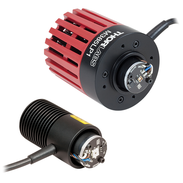
Like our mounted LEDs, the package of these collimated LEDs is in direct contact with the heat sink to provide excellent thermal management. This minimizes the degradation of optical output power caused by increased LED temperatures. Please see the Stability tab for information on the stable output intensity of these collimated LEDs. Additionally, our M365LP1, M385LP1, and M405LP1 LEDs feature a higher power output and are mounted to a larger Ø57.0 mm heat sink to increase heat dissipation and thermal stability.
For microscope applications requiring compatibility with SM1 (1.035"-40) threading, our mounted LEDs (sold separately) can be collimated using a Ø1" lens and lens tubes. This collimation method also allows for a smaller beam size than the collimators on this page. Please see the Collimation tab on our Mounted LEDs presentation for a detailed item list and instructions.
Driver Options
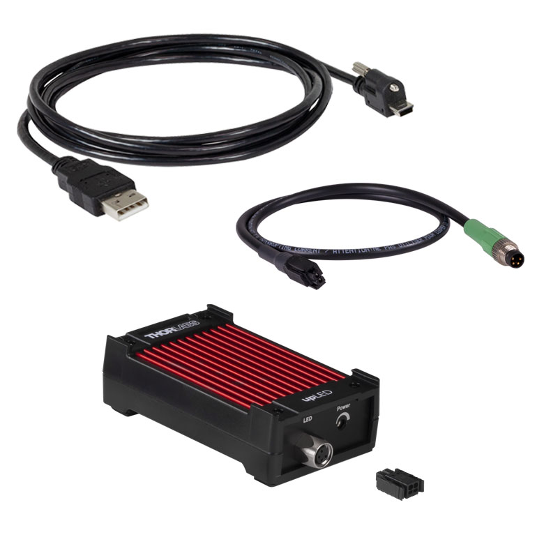
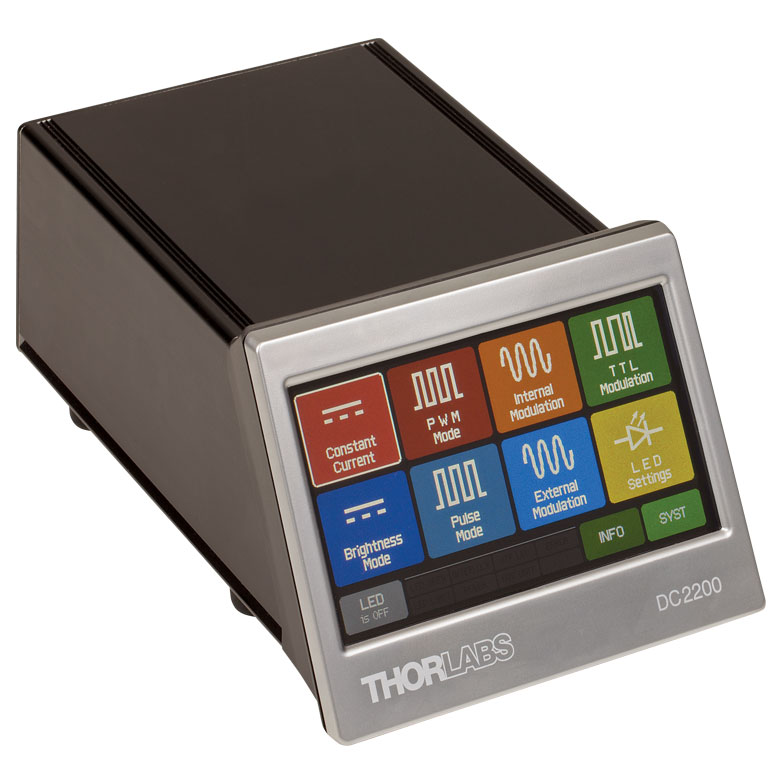
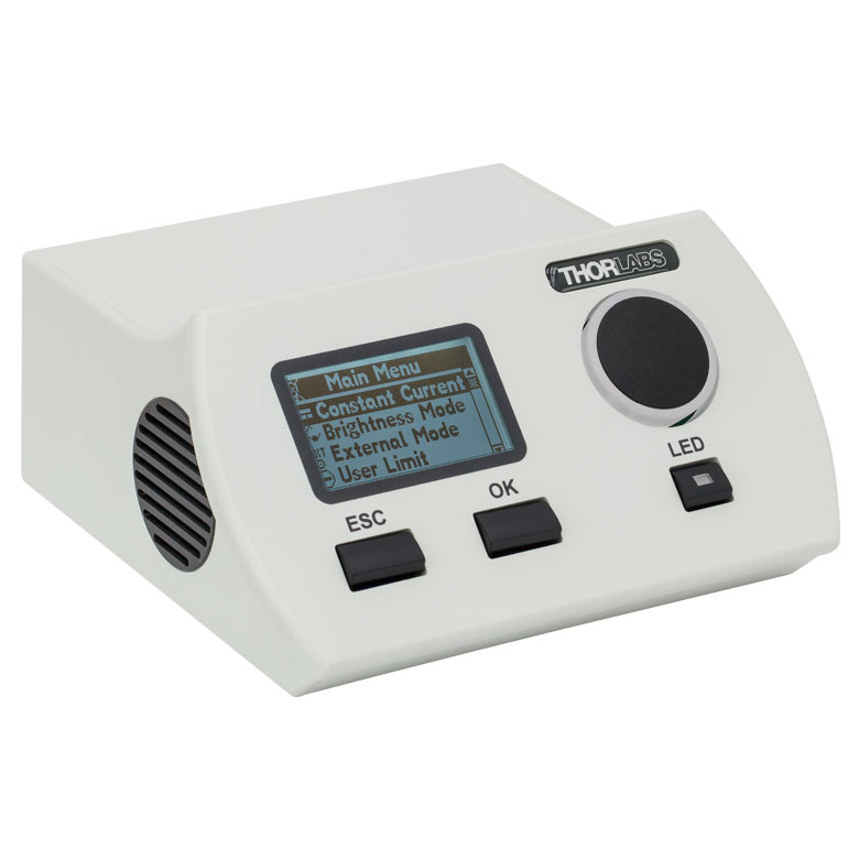
Thorlabs offers five drivers compatible with these LEDs: LEDD1B, UPLED, DC2200, DC4100, and DC4104 (the latter two require the DC4100-HUB). The UPLED, DC2200, DC4100, and DC4104 drivers are capable of reading the current limit from the EEPROM chip of the connected LED and automatically adjusting the maximum current setting to protect the LED. See the LED Drivers tab for specifications and comparison between the drivers.
Common LED Specificationsa
| Legend | |
|---|---|
| LED Mounted to a Heat Sink in a Ø57.0 mm Red Housing | LED Mounted to a Heat Sink in a Ø30.5 mm Black Housing |
| Item # Prefix | Nominal Wavelengthb,c |
Colorb | Min LED Powerb,d |
Typ. LED Powerb,d | Max Drive Current (CW) |
Forward Voltage (Typ.) |
Irradiance (Typical)d |
Electrical Power |
Typical Lifetime |
Emitter Size |
|---|---|---|---|---|---|---|---|---|---|---|
| M365L3e | 365 nm | UV | 880 mW | 1290 mW | 1000 mA | 3.85 V | 14.4 µW/mm2 | 3.850 W | >10 000 h | 2.5 mm x 2.5 mm |
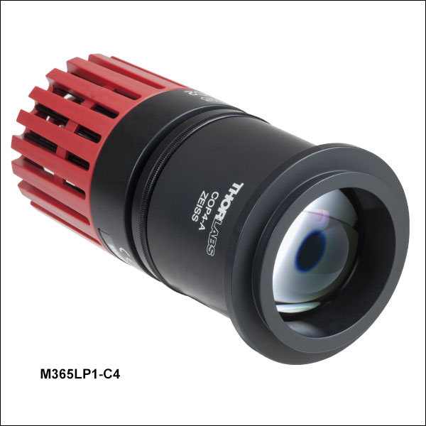
| M365LP1e,f | 365 nm | UV | 1350 mW | 2000 mW | 1700 mA | 4.0 V | 21.0 µW/mm2 | 6.800 W | >10 000 h | 2.5 mm x 2.5 mm |
| M385L2e | 385 nm | UV | 270 mW | 430 mW | 700 mA | 4.3 V | 11.8 µW/mm2 | 3.010 W | >10 000 h | 1 mm x 1 mm |
| M385L3e | 385 nm | UV | 1240 mW | 1780 mW | 1000 mA | 3.7 V | 19.9 µW/mm2 | 3.700 W | >10 000 h | 2.5 mm x 2.5 mm |
| M385LP1e,f | 385 nm | UV | 1650 mW | 1830 mW | 1700 mA | 3.9 V | 23.3 µW/mm2 | 6.630 W | >10 000 h | 1.4 mm x 1.4 mm |
| M405L4e | 405 nm | UV | 1000 mW | 1300 mW | 1000 mA | 3.4 V | 14.53 µW/mm2 | 3.400 W | > 1 000 h | 1.4 mm x 1.4 mm |
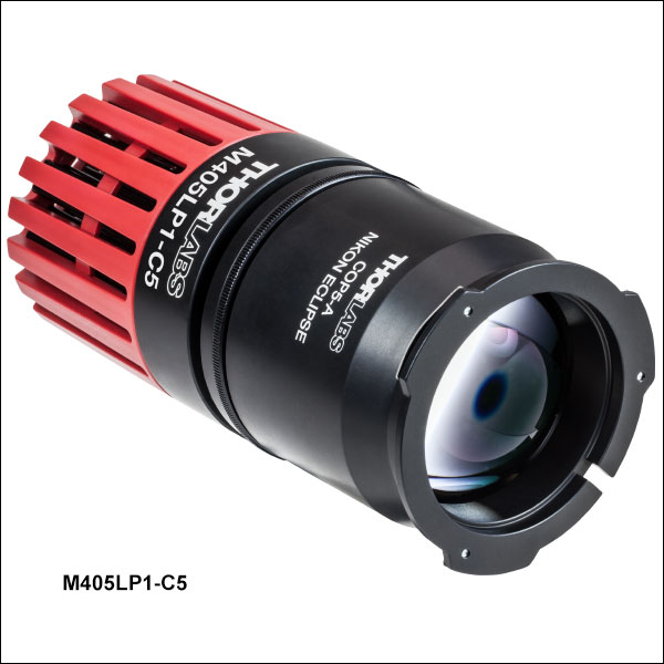
| M405LP1e,f | 405 nm | UV | 1500 mW | 1700 mW | 1400 mA | 3.45 V | 24.6 µW/mm2 | 4.830 W | >10 000 h | 1.4 mm x 1.4 mm |
| M455L4 | 455 nm | Royal Blue | 1150 mW | 1445 mW | 1000 mA | 3.25 V | 32 µW/mm2 | 1.900 W | >100 000 h | 1 mm x 1 mm |
| M470L5 | 470 nmg,h | Blue | 809 mWg,h | 1161.7 mWg,h | 1000 mAg | 3.8 V | 21.4g,h,i µW/mm2 | 3.820 Wg,h | >100 000 hg | 1 mm x 1 mm |
| M505L4 | 505 nm | Cyan | 400 mW | 520 mW | 1000 mA | 3.5 V | 5.94 µW/mm2 | 3.500 mW | >100 000 h | 1 mm x 1 mm |
| M530L4 | 530 nm | Green | 370 mW | 480 mW | 1000 mA | 3.6 V | 9.46 µW/mm2 | 3.600 W | >100 000 h | 1 mm x 1 mm |
| M590L4 | 590 nm | Amber | 230 mW | 300 mW | 1000 mA | 2.5 V | 6.0 µW/mm2 | 2.500 W | >100 000 h | 1 mm x 1 mm |
| M617L5 | 617 nm | Orange | 737.4 mWg,h | 1006.2 mWg,h | 1000 mAg | 2.9 Vg,h | 19.4 µW/mm2 g,h,i | 2.915 Wg | >100 000 hg | 1 mm x 1 mm |
| M625L4 | 625 nm | Red | 700 mW | 920 mW | 1000 mA | 2.5 V | 21.9 µW/mm2 | 2.500 W | 100 000 h | 1 mm x 1 mm |
| M660L4 | 660 nm | Deep Red | 940 mW | 1050 mW | 1200 mA | 2.6 V | 20.88 µW/mm2 | 3.120 W | >10 000 h | 1.5 mm x 1.5 mm |
| M780L3 | 780 nm | IR | 200 mW | 300 mW | 800 mA | 2.0 V | 47.3 µW/mm2 | 1.600 W | >10 000 h | 1 mm x 1 mm |
| M810L3 | 810 nm | IR | 325 mW | 375 mW | 500 mA | 3.6 V | 61.8 µW/mm2 | 1.800 W | >10 000 h | 1 mm x 1 mm |
| M850L3 | 850 nm | IR | 900 mW | 1100 mW | 1200 mA | 2.95 V | 22.9 µW/mm2 | 3.540 W | 100 000 h | 1 mm x 1 mm |
| M940L3 | 940 nm | IR | 800 mW | 1000 mW | 1000 mA | 2.75 V | 19.1 µW/mm2 | 2.750 W | 100 000 h | 1 mm x 1 mm |
| MCWHL8 | N/Aj | Cold White | 1300.9 mWg,h | 1882.0 mWg,h | 1400 mAg | 3.6 Vg,h | 22.5 µW/mm2 g,h,i | 5040 mWg | >100 000 hg | Ø3 mm |
Specifications for LED with Collimating Microscope Adapter Attached
| Legend | |
|---|---|
| LED Mounted to a Heat Sink in a Ø57.0 mm Red Housing | LED Mounted to a Heat Sink in a Ø30.5 mm Black Housing |
| Item # Suffix | -C1 | -C2 | -C4 | -C5 | |
|---|---|---|---|---|---|
| Compatible Microscopea | Olympus BX and IX | Leica DMI | Zeiss Axioskop and Examinerb | Nikon Eclipse (Bayonet Mount) | |
| Beam Diameterc,d | 50 mm | 37 mm | 44 mm | 43 mm | |
| Beam Areac | 1960 mm² | 1080 mm² | 1520 mm² | 1450 mm² | |
| Item # Prefix | Included Collimation Lens | Total Beam Powerc,d | |||
| M365L3 | ACL5040U-A | 520 mW | 320 mW | 430 mW | 320 mW |
| M365LP1 | ACL5040U-A | 745 mW | 435 mW | 615 mW | 435 mW |
| M385L2 | ACL5040U-A | 170 mW | 90 mW | 110 mW | 120 mW |
| M385L3 | ACL5040U-A | 680 mW | 450 mW | 570 mW | 410 mW |
| M385LP1 | ACL5040U-A | 795 mW | 520 mW | 660 mW | 630 mW |
| M405L4 | ACL5040U-A | 510 mW | 310 mW | 410 mW | 380 mW |
| M405LP1 | ACL5040U-A | 750 mW | 450 mW | 580 mW | 570 mW |
| M455L4 | ACL5040U-A | 630 mW | 490 mW | 690 mW | 630 mW |
| M470L5 | ACL5040U-A | 487 mW | 402 mW | 521 mW | 487 mW |
| M505L4 | ACL5040U-A | 220 mW | 170 mW | 240 mW | 220 mW |
| M530L4 | ACL5040U-A | 200 mW | 160 mW | 220 mW | 200 mW |
| M590L4 | ACL5040U-A | 130 mW | 100 mW | 140 mW | 130 mW |
| M617L5 | ACL5040U-A | 484 mWe | 362 mWe | 474 mWe | 441 mWe |
| M625L4 | ACL5040U-A | 630 mW | 490 mW | 690 mW | 630 mW |
| M660L4 | ACL5040U-A | 590 mW | 400 mW | 570 mW | 520 mW |
| M780L3 | ACL5040U-B | 210 mW | 130 mW | 180 mW | 170 mW |
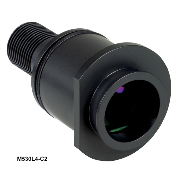
| M810L3 | ACL5040U-B | N/A | 210 mW | N/A | N/A |
| M850L3 | ACL5040U-B | 480 mW | 330 mW | 400 mW | 370 mW |
| M940L3 | ACL5040U-B | 430 mW | 320 mW | 380 mW | 340 mW |
| MCWHL8 | ACL5040U-A | 658 mWf | 419 mWf | 596 mWf | 549 mWf |
The actual spectral output and total output power of any given LED will vary due to variations in the manufacturing process and operating parameters, such as temperature and current. The typical total beam power of each collimated LED is specified to help you select an LED that suits your needs. In order to provide a point of comparison for the relative powers of LEDs with different nominal wavelengths, the spectra in the plots below have been scaled to the typical total beam power of each collimated LED. This data is representative, not absolute. An Excel file containing the normalized and scaled spectra for each collimation package can be downloaded using the link below each plot.
Collimated LEDs for Olympus BX and IX Microscopes
Click to Enlarge
An Excel file containing the data shown in the plot above may be found here.
Collimated LEDs for Leica DMI Microscopes
Click to Enlarge
An Excel file containing the data shown in the plot above may be found here.
Collimated LEDs for Nikon Eclipse Microscopes
Click to Enlarge
An Excel file containing the data shown in the plot above may be found here.
Collimated LEDs for Zeiss Axioskop and Examiner Microscopes

Click to Enlarge
An Excel file containing the data shown in the plot above may be found here.
LED Lifetime and Long-Term Power Stability
One characteristic of LEDs is that they naturally exhibit power degradation with time. Often this power degradation is slow, but there are also instances where large, rapid drops in power, or even complete LED failure, occur. LED lifetimes are defined as the time it takes a specified percentage of a type of LED to fall below some power level. The parameters for the lifetime measurement can be written using the notation BXX/LYY, where XX is the percentage of that type of LED that will provide less than YY percent of the specified output power after the lifetime has elapsed. Thorlabs defines the lifetime of our LEDs as B50/L50, meaning that 50% of the LEDs with a given Item # will fall below 50% of the initial optical power at the end of the specified lifetime. For example, if a batch of 100 LEDs is rated for 150 mW of output power, 50 of these LEDs can be expected to produce an output power of ≤75 mW after the specified LED lifetime has elapsed.
Optimized Thermal Management
The thermal dissipation performance of these collimated LEDs has been optimized for stable power output. The heat sink is directly mounted to the LED mount so as to provide optimal thermal contact. By doing so, the degradation of optical output power that can be attributed to increased LED junction temperature is minimized (see the graph to the right).
| Pin | Specification | Color |
|---|---|---|
| 1 | LED Anode | Brown |
| 2 | LED Cathode | White |
| 3 | EEPROM GND | Black |
| 4 | EEPROM IO | Blue |

Pin Connection - Male
The diagram to the right shows the male connector of the collimated LED assembly. It is a standard M8 x 1 sensor circular connector. Pins 1 and 2 are the connection to the LED. Pin 3 and 4 are used for the internal EEPROM in these LEDs. If using an LED driver that was not purchased from Thorlabs, be careful that the appropriate connections are made to Pin 1 and Pin 2 and that you do not attempt to drive the LED through the EEPROM pins.
To fully support the maximum optical power of the LED you intend to drive, ensure that the max voltage and max current of the driver are equal to or greater than those of the LED.
| Compatible Drivers | LEDD1B | UPLEDa | DC2200a | DC4100a,b | DC4104a,b |
|---|---|---|---|---|---|
| Click Photos to Enlarge |  |
 |
 |
 |
 |
| LED Driver Current Output (Max)c | 1.2 A | 1.2 A | LED1 Terminal: 10.0 A LED2 Terminal: 2.0 Ad |
1.0 A per Channel | 1.0 A per Channel |
| LED Driver Forward Voltage (Max) | 12 V | 8 V | 50 V | 5 V | 5 V |
| Modulation Frequency Using External Input (Max) | 5 kHz | - | 250 kHze,f | 100 kHzf (Simultaneous Across all Channels) |
100 kHzf (Independently Controlled Channels) |
| External Control Interface(s) | Analog (BNC) | USB 2.0 | USB 2.0 and Analog (BNC) | USB 2.0 and Analog (BNC) | USB 2.0 and Analog (8-Pin) |
| Main Driver Features | Very Compact Footprint 60 mm x 73 mm x 104 mm (W x H x D) |
USB-Controlled | Touchscreen Interface with Internal and External Options for Pulsed and Modulated LED Operation | 4 Channelsb | 4 Channelsb |
| EEPROM Compatible: Reads Out LED Data for LED Settings | - | ||||
| LCD Display | - | - |
| Posted Comments: | |
Yeon Jae Yoo
(posted 2022-11-01 08:57:41.63) Hello. My name is YeonJae Yoo, who works for LG Chem in Korea. I am writing this email because I have an inquiry regarding the purchase of a 365nm wavelength LED. If I buy this product, will the 365nm LED collimated beam come out without any other accessories? I want to know if I need to purchase another driver. Please reply by e-mail. hchow
(posted 2022-11-02 05:38:44.0) Hi Ms. Yoo, thank you for your enquiry. I will personally reach out to you to provide more information. user
(posted 2021-03-23 20:31:18.53) Dear sir,
I am looking for collimated LED light sources which are internally or externally SM2 threaded (like Solice LEDs). This would be very universal and convenient for integrating them with other thorlabs optics. They can be surely compatible with microscopes using, for example, SM2A13. I have a Solice LED for this purpose but need lighter one such as MCWHL6-C1. Alternatively, it would be great for you to provide adapters to fit MCWHL6-C1 to SM2 threaded parts. Thanks. MKiess
(posted 2021-03-25 11:13:07.0) Thank you very much for this feedback.
You can use a MCWHL6 LED in combination with a SM2F32-A, adjustable collimation adapter for Ø2" (Ø50 mm) Optics for this purpose. The MCWHL6 is the same LED that is also used for the MCWHL6-C1. You can screw the SM2F32-A collimator directly to this LED. The collimator has an internal SM2 thread for further integration. Patrick Lee
(posted 2021-03-09 11:23:47.873) Hi, I am interested in MCWHL6-C1.
I plan to use it as a collimated light source to shine on a test object, in order to cast a shadow on a diffuser glass.
A camera is placed at back of diffuser to pick up the shadow.
a) what is divergence output ?
b) will shadow be sharp ?
c) any recommendation for power supplier ?
Thank you. MKiess
(posted 2021-03-11 08:59:36.0) Dear Patrick,
Thank you for your inquiry.
A suitable LED driver for the MCWHL6-C1, is the LEDD1B or the DC2200. The divergence and sharpness of the shadow depends on your overall optical system of diffuser and lenses used, as well as the camera parameters. I have contacted you directly to discuss the details. user
(posted 2021-02-13 00:38:28.523) Hi, I am interested in using the MCWHL6-C5 to replace a 12V100W halogen lamphouse on my Nikon microscope. Roughly speaking, would the total output (477 mW) be comparable to the total output of the halogen bulb? MKiess
(posted 2021-02-15 11:03:51.0) Thank you very much for your inquiry. It depends on what the exact output power of the halogen lamp is. I assume that it will be a little higher than that of this LED. Cold white, LEDs with higher output power, which can also be connected to the Nikon microscope with corresponding collimators or adapters (As can be found, for example, under the following link.: https://www.thorlabs.de/newgrouppage9.cfm?objectgroup_id=8706) would be the SOLIS-1C and the MCWHLP1.
I have contacted you directly to discuss the exact requirement together. Hajun Song
(posted 2020-11-09 01:50:49.14) I want to use this model as a flash lamp for the high speed camera. What is the eletrical bandwidth of the laser? Is it possble to modulate the LD as a short pulse modulation? How narrow? wskopalik
(posted 2020-11-09 10:39:33.0) Dear Hajun,
Thank you very much for your feedback.
Unfortunately we do not have any data about the rise time of the M780L3-C1. Usually the bandwidth of LEDs is limited by the driver electronics rather than by the LED itself. So the specifications of the driver would need to be considered in most cases.
A good assumption for the rise time of an LED without phosphor like the M780L3-C1 is the range of at least 100 ns. This corresponds to an 3dB bandwidth of 3.5 MHz. Phosphor-converted LEDs (e.g. for white light) can however be considerably slower than that.
I will contact you directly so we can talk about your requirements in more detail. yefan8900
(posted 2019-02-07 15:20:32.607) can you please recommend me a led driver of this led? 1600 mA swick
(posted 2019-02-15 05:12:49.0) This is a response from Sebastian at Thorlabs. Thank you for the inquiry.
Our DC2200 can be used to drive LEDs at 1600 mA. yefan8900
(posted 2019-02-07 14:11:44.557) what's the beam power of M470L2-C3 - Blue (470 nm)? the spec sheet does not have such information. only have information about M470L2-C1, M470L2-C2, M470L2-C4, M470L2-C5. nreusch
(posted 2019-04-15 10:48:41.0) This is a response from Nicola at Thorlabs. Thank you for your inquiry! The total beam power is 300 mW. I will send you the spec sheet via email. yefan8900
(posted 2019-02-06 22:17:30.557) Can you send me the spec sheet of M470L2-C3? The spec sheet above did not include M470L2-C3, which is very weird. nreusch
(posted 2019-04-15 10:48:38.0) Thank you for your inquiry! Please find my response below your second post. e.zherebtsov
(posted 2017-08-04 02:35:01.72) Could you consult me please whether it is possible to modulate the LEDs at 365 nm with frequency ~50 MHz. Thanks a lot. tschalk
(posted 2017-08-07 09:13:59.0) This is a response from Thomas at Thorlabs. These high power LEDs are not well suited to perform a modulation in the MHz range. We will contact you directly with more detailed information. iravkin
(posted 2017-08-02 09:50:36.14) Could you explain the procedure and the light meters used to measure the Total Beam Power at the output aperture of collimated LED light sources? Do you offer the required power meters if I want to perform these measurements in my lab? tfrisch
(posted 2017-08-16 10:36:19.0) Hello, thank you for contacting Thorlabs. These collimated LEDs are measured using an integrating sphere which is unfortunately not a component we offer. We will reach out to you directly as well. tzangle
(posted 2017-01-18 22:29:19.993) What is the "separate adapter that is available from Olympus." that may be necessary to use this with an IX series microscope as a transmitted light source? wskopalik
(posted 2017-01-24 06:24:23.0) This is a response from Wolfgang at Thorlabs. Thank you very much for your inquiry.
The collimated LED light sources for Olympus BX and IX microscopes can be directly attached to the epi-illumination port of these microscopes. For the transmission-illumination port we might be able to offer a suitable collimator as a special.
I have contacted you directly to provide further information and to discuss the issue in more detail. bmsalzbe
(posted 2016-02-29 11:41:02.43) Need amplitude noise information at 530 nm and 470 nm shallwig
(posted 2016-03-03 09:53:52.0) This is a response from Stefan at Thorlabs. Thank you very much for your inquiry. I will contact you directly to check your setup and your application in detail. giulia.mazza
(posted 2014-03-20 10:48:54.817) Hello! The LED M455L3 would suite my application, I'm looking for possibilities to collimate it correctly ideally in a small beam with low divergence.. I do not need it for microscopy.
A 5 cm diameter beam is quite big but if the collimation is good I could resize it with further optics, so the first question is "which is the divergence of the beam after collimation in the product M455L3-C1"?
Second question, are there other possibilities to collimate the M455L3 LED in for example a < 1.5 cm beam with divergence < 5°? How much power loss should it cause?? Thanks in advance!!! jvigroux
(posted 2014-04-10 10:10:14.0) A response from Julien at Thorlabs: Thank you for your inquiry! The divergence of the M455L3-C1is typically of about 3° and in best case slightly less than 2°, so that in principle it would be possible to resize the beam after the 2" output. By using another collimating lens than the standard 2" diameter 40mm focal length, one can further reduce the output collimated beam. I will contact you directly to discuss the requirements in termsof powe and divergence in order to see which option would work best in your case. mwinkler.its-b2011
(posted 2013-09-26 07:33:22.427) Hello,
I have bought the MCWHL5-C1 and I would like to mount it externally on a bar to a device.
Sadly I am not sure which mount I should best use where I can put the device in and connect it to the bar with screws.
Can you recommend me a device from your catalogue which is best suited for that?
Thanks in advance tschalk
(posted 2013-10-04 08:15:00.0) This is a response from Thomas at Thorlabs. Thank you very much for your inquiry. To mount our collimated LED light sources you can use a lens tube slip ring SM1RC: https://www.thorlabs.de/newgrouppage9.cfm?objectgroup_id=1533&pn=SM1RC#2714. I will contact you directly with more detailed information. mhunter
(posted 2013-09-11 14:07:09.973) I am very interested in using an LED light source in place of a 100 watt halogen lamp -- in the EPI illuminators of my (6) Nikon Optiphot 150 microscopes. We are primarily using brightfield and DIC imaging.
Would your mounted LEDs (probably cool white or green) work in this application?
Thanks, Mike Hunter tschalk
(posted 2013-09-13 09:50:00.0) A response from Thomas at Thorlabs. Thank you very much for your inquiry. At the moment we don’t have an adapter which is suitable for the Nikon Optiphot 150 microscopes. I will contact you directly to check if we can find a solution. B.Povazay
(posted 2013-03-12 19:54:38.977) Is it possible to mount collimated LEDs in a standard SM1-mount? tcohen
(posted 2013-03-14 13:37:00.0) Response from Tim at Thorlabs: The back end of these have 1.2” diameters and can be used with an SM1RC slip ring. The beam diameters produced by these larger focal length lenses would overfill an SM1 thread. If you are looking to confine it to this size an alternative would be to use the mounted LED without the collimating optic, (this is the M***L2 series and can be purchased separately) and then use a 1” diameter lens with an adjustable length lens tube for alignment. We have a typical setup to this end on our “Application” tab on the M***L2 series page. jvigroux
(posted 2012-10-22 08:48:00.0) A response form Julien at Thorlabs: Thank you for your inquiry! As far as I know, DIC usually uses polarized light sources. If this is the cas ein your setup, the LEd would not work because of the light being unpolarized. The use of an extra polarizer after the LED would imply a strong power reduction as well as a relatively high instability of the output power. I will contact you directly to discuss the details of your setup in order to see which light source could be used. nrbabuwp
(posted 2012-10-18 18:45:29.41) Hi,
We are interested in buying an LED to replace the lamp of DIC to use it in multicolor imaging. Wavelength range we are looking for is between 670 and 750nm. Can you suggest if 260mW of 735nm LED is good enough for DIC imaging? Has anyone used it for DIC?
Babu jvigroux
(posted 2012-01-23 10:30:00.0) A response from Julien at Thorlabs: Thank you for your feedback! the suggested adapters are by no mean the only solution and based on the details of your setup, some other configuration might indeed improve the power density or the homogeneity. I will contact you directly to discuss the details and see which solution would be the most adapted. g.raffy
(posted 2012-01-23 09:12:12.0) A collimated beam with 50mm diameter will be clipped by the back aperture of the objective in an IX microscope (~10mm), loosing most of the available power of the LED. Am I wrong?
Why not proposing an alternative lens that lets all the light entering the objective? I really need all the power...
Ideally, if the lens to LED distance is settable, then one could choose between power density and uniformity of illumination. bdada
(posted 2011-09-21 14:55:00.0) Response from Buki at Thorlabs:
Thank you for your interest in our MCWHL2-C1 and for taking the time to use our feedback tool! These mounts are designed to fit on the standard and epi-illumination ports for Olympus BX and IX microscopes. The exact compatibility will depend on whether the transmitted lamp housing on your desired Olympus microscope has the same port-style as the BX and IX.
Please contact TechSupport@thorlabs.com if you have further inquiries. mzlin
(posted 2011-09-02 12:01:15.0) Can anyone verify that the Olympus mounts will fit in place of the transmitted lamp housing too (i.e. the same mount will work for transmitted as for fluorescence)? We have not gotten our scope yet so cant measure ourselves. Thanks. klee
(posted 2009-10-05 16:12:24.0) A response from Ken at Thorlabs: Our new DC2100 is also plug and play compatible with these LED light sources. acable
(posted 2009-10-03 15:47:55.0) Is the LEDD1 driver the only driver you offer that is plug and play compatible. |
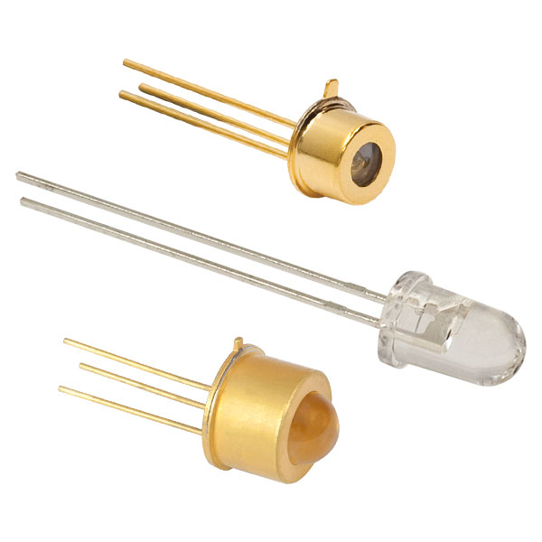
This tab includes all LEDs sold by Thorlabs. Click on More [+] to view all available wavelengths for each type of LED pictured below.
| Light Emitting Diode (LED) Selection Guide | ||||||
|---|---|---|---|---|---|---|
| Click Photo to Enlarge (Representative; Not to Scale) |
 |
 |
 |
 |
 |
 |
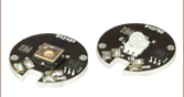
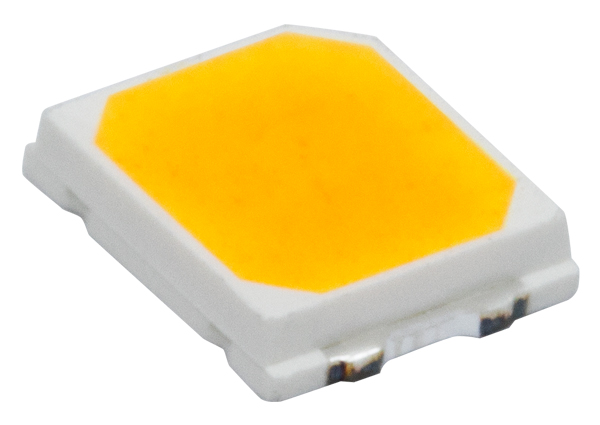
| Type | Unmounted LEDs | Pigtailed LEDs | LEDs in SMT Packages |
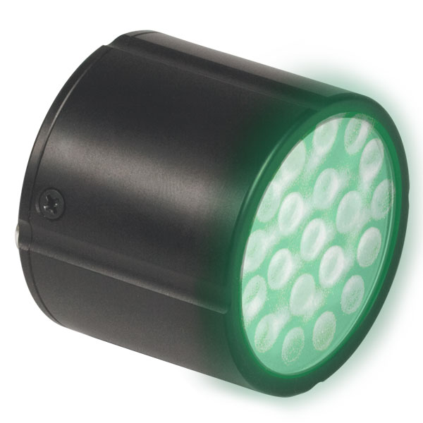
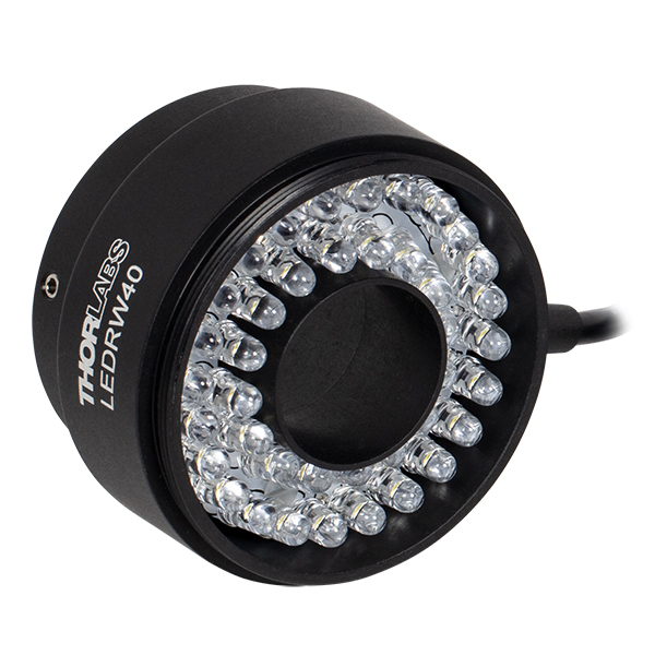
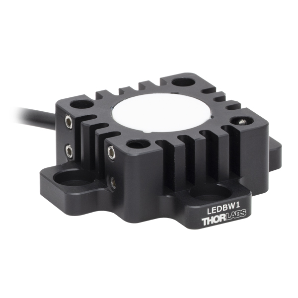
LED Arrays | LED Ring Light | Cage-Compatible Diffuse Backlight LED |
| Light Emitting Diode (LED) Selection Guide | ||||||
|---|---|---|---|---|---|---|
| Click Photo to Enlarge (Representative; Not to Scale) |
 |
 |
 |
 |
 |
 |
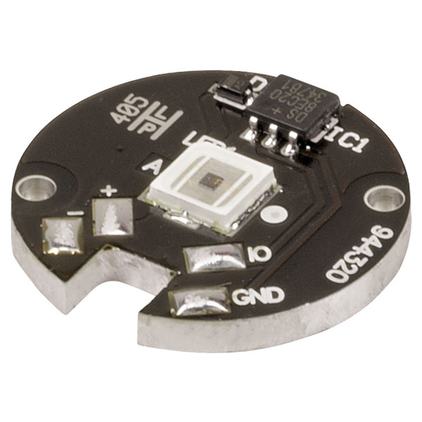
| Type | PCB- Mounted LEDs |
Heatsink- Mounted LEDs |
Collimated LEDs for Microscopyb | Fiber- Coupled LEDsc |
High-Power LEDs for Microscopy | Multi-Wavelength LED Source Optionsd |

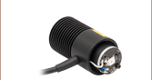
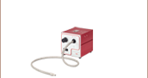
 Zoom
Zoom- Approximate Beam Diameter: 50 mm
- Approximate Beam Area: 1960 mm²
- AR-Coated Aspheric Collimation Lens (EFL: 40 mm)
- See the Specs Tab for a Complete List of Specifications
- Cable Length: 2 m

 Zoom
Zoom- Approximate Beam Diameter: 37 mm
- Approximate Beam Area: 1080 mm²
- AR-Coated Aspheric Collimation Lens (EFL = 40 mm)
- See the Specs Tab for a Complete List of Specifications
- Cable Length: 2 m


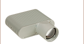
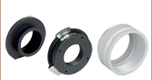
 Zoom
Zoom- Approximate Beam Diameter: 44 mm
- Approximate Beam Area: 1520 mm²
- Compatible with Dovetail Used in Zeiss Axioskop and Examiner Microscopes
- AR-Coated Aspheric Collimation Lens (EFL: 40 mm)
- See the Specs Tab for a Complete List of Specifications
- Cable Length: 2 m
 Microscopes")
 Zoom
Zoom- Approximate Beam Diameter: 43 mm
- Approximate Beam Area: 1450 mm²
- AR-Coated Aspheric Collimation Lens (EFL: 40 mm)
- See the Specs Tab for a Complete List of Specifications
- Cable Length: 2 m

 Zoom
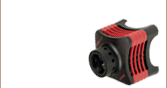
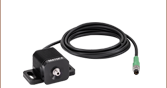
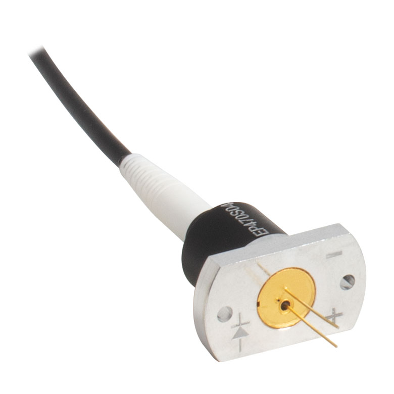
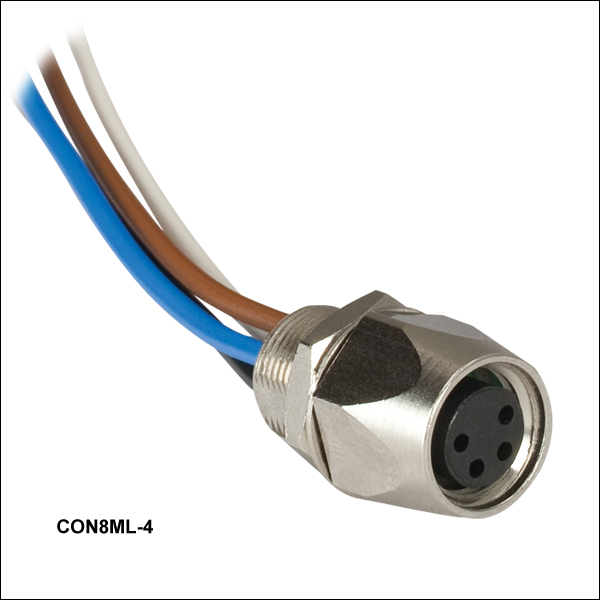
Zoom- Female 4-Pin Pico (M8) Receptacle
- M8 x 1 Thread for Connection to Mounted LED Power Cable
- M8 x 0.5 Panel-Mount Thread for Custom Housings
- 0.5 m Long, 24 AWG Wires
- IP 67 and NEMA 6P Rated
The CON8ML-4 connector can be used to mate mounted LEDs featured on this page to user-supplied power supplies. We also offer a male 4-Pin M8 connector cable (item # CAB-LEDD1).
| Pin | Color | Specification | 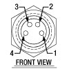 |
|---|---|---|---|
| 1 | Brown | LED Anode | |
| 2 | White | LED Cathode | |
| 3 | Black | EEPROM GND | |
| 4 | Blue | EEPROM IO |
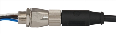
CON8ML-4 Shown Connected to the 4-Pin M8 Plug of Mounted LED