 Products Home
Fiber-Coupled LEDs
- UV, Visible, and NIR Versions
- Optimized Heat Management Results in Stable Output
- Integrated Chip Stores LED Operating Parameters
- Accepts SMA Fiber Connector
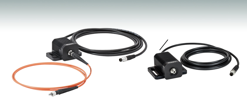
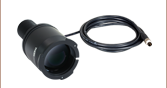
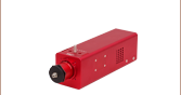
M625F2
625 nm Fiber-Coupled LED
Ø400 µm Core Patch Cable
(Not Included)
Integrated Power Cable
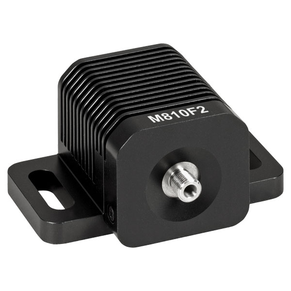
Large Heat Sink for
Optimized Heat Dissipation
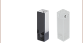
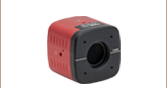
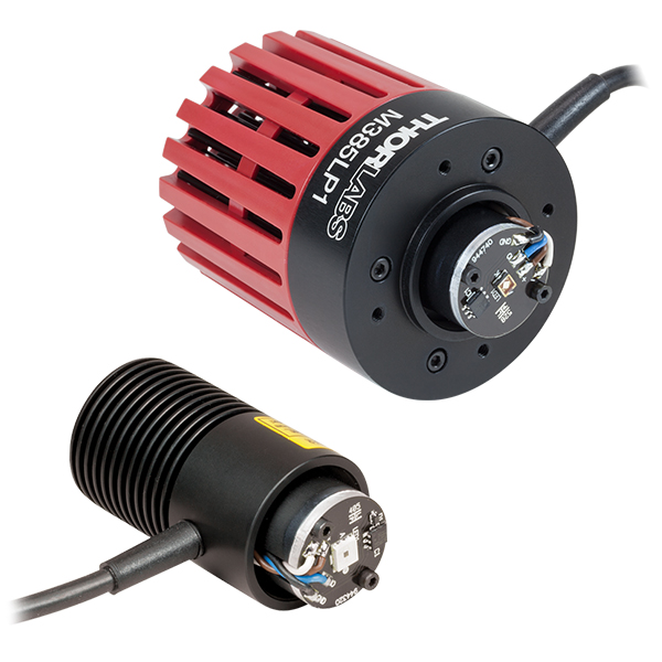
M385FP1
385 nm Fiber-Coupled LED


Please Wait
| Legend | |
|---|---|
| LED Mounted to a 50 mm Long Heat Sink | LED Mounted to a 34 mm Long Heat Sink |
| Item # | Color (Click for Spectrum)a |
Nominal Wavelengtha,b |
Ø200 µm Core Fiber Output (Typ.)c,d,e |
Ø400 µm Core Fiber Output (Typ.)c,e,f |
|---|---|---|---|---|
| M280F5g | Deep UV | 280 nm | 0.2 mW | 0.8 mW |
| M310F1g | Deep UV | 308 nm | 0.14 mW | 0.51 mW |
| M325F4g | Deep UV | 325 nm | 100 µW | 350 µW |
| M340F4g | Deep UV | 340 nm | 0.16 mW | 0.75 mW |
| M365FP1g | UV | 365 nm | 5.29 mW | 15.5 mW |
| M375F3g | UV | 375 nm | 1.57 mW | 4.23 mW |
| M385F1g | UV | 385 nm | 2.68 mW | 10.7 mW |
| M385FP1g | UV | 385 nm | 7.7 mW | 23.2 mW |
| M395F3g | UV | 395 nm | 1.91 mW | 6.8 mW |
| M395FP1g | UV | 395 nm | 7.7 mW | 29.8 mW |
| M405F3g | UV | 405 nm | 0.93 mW | 3.7 mW |
| M405FP1g | UV | 405 nm | 7.7 mW | 24.3 mW |
| M415F3g | Violet | 415 nm | 7.0 mW | 21.3 mW |
| M430F1g | Violet | 430 nm | 2.9 mW | 7.5 mW |
| M455F3 | Royal Blue | 455 nm | 5.4 mW | 24.5 mW |
| M470F4 | Blue | 470 nm | 6.5 mW | 20 mW |
| M490F4 | Blue | 490 nm | 0.9 mW | 2.8 mW |
| M505F3 | Cyan | 505 nm | 3.7 mW | 11.7 mW |
| M530F3 | Green | 530 nm | 3.2 mW | 9.6 mW |
| MINTF4 | Mint | 554 nm | 8.5 mW | 28 mW |
| M565F3h | Lime | 565 nm | 4.4 mW | 13.5 mW |
| M590F3 | Amber | 590 nm | 1.5 mW | 4.6 mW |
| M595F2h | PC Amber | 595 nm | 4.0 mW | 11.5 mW |
| M617F2 | Orange | 617 nm | 4.4 mW | 13.2 mW |
| M625F2 | Red | 625 nm | 5.7 mW | 17.5 mW |
| M660FP1 | Red | 660 nm | 4.7 mW | 15.5 mW |
| M680F4 | Deep Red | 680 nm | 2.8 mW | 9 mW |
| M740F2 | Far Red | 740 nm | 2.1 mW | 6.0 mW |
| M780F2 | IR | 780 nm | 1.15 mW | 7.0 mW |
| M810F3 | IR | 810 nm | 6.1 mW | 19.3 mW |
| M850F3 | IR | 850 nm | 4.1 mW | 13.4 mW |
| M880F2 | IR | 880 nm | 0.58 mW | 3.4 mW |
| M940F3 | IR | 940 nm | 4.2 mW | 14.2 mW |
| M970F3 | IR | 970 nm | 2.4 mW | 8.1 mW |
| M1050F3 | IR | 1050 nm | 0.92 mW | 3.0 mW |
| M1100F1 | IR | 1100 nm | 1.1 mW | 5.4 mW |
| M1200F1 | IR | 1200 nm | 0.9 mW | 2.5 mW |
| M1300F1 | IR | 1300 nm | 0.77 mW | 2.31 mW |
| M1450F1 | IR | 1450 nm | 0.44 mW | 1.34 mW |
| MBB1F1i | Broadband | 470 - 850 nmj | 0.30 mW | 1.2 mW |
| MWWHF2k | Warm White | 4000 Kl | 7.9 mW | 23.1 mW |
| MCWHF2k | Cold White | 6200 Kl | 8.8 mW | 27.0 mW |
Features
- Nominal Wavelengths Ranging from 280 nm to 1450 nm
- Warm White (4000 K), Cold White (6200 K), and Broadband (470 - 850 nm) LEDs Also Available
- Integrated Identification Chip (EEPROM) Stores LED Operating Parameters
- Optimized Thermal Properties Lead to Stable Output Power
- SMA Bulkheads Are Ideal for Use with Multimode Fiber Optic Patch Cables
Each fiber-coupled LED consists of a single LED that is coupled to the optical fiber using the butt-coupling technique. During this process, the fiber connector is positioned so that the end of the fiber will be as close as possible to the emitter, thereby minimizing losses at the fiber input and maximizing output power. The coupling efficiency is primarily dependent on the core diameter and the numerical aperture (NA) of the connected fiber. Larger core diameters and higher NA values give rise to reduced losses and increased output power at the end of the fiber. Additionally, high-OH content or solarization-resistant fibers are recommended for use with LED wavelengths below 400 nm (please refer to the table below for recommended patch cables).
Please note that the connectors on these fiber-coupled LEDs are intended for SMA connectors only. To prevent mechanical damage to the LED, the ferrule length of the attached connector must not exceed the maximum length for SMA connectors of 9.812 mm as defined by the EN61754-22:2005 standard.
The spectrum of each LED and associated data file can be viewed by clicking on the links in the table to the right. Multiple windows can be opened simultaneously in order to compare LEDs.
Optimized Thermal Management
These fiber-coupled LEDs possess good thermal stability properties. The 34 mm long, passively cooled heat sink used in most of our fiber-coupled LEDs is in direct contact with the metal-core circuit board on which the LED is mounted. This minimizes the degradation of optical output power caused by increased LED junction temperature. Some of our fiber-coupled LEDs with a higher power output (M365FP1, M385FP1, M395FP1, M405FP1, and M660FP1) are mounted to a 50 mm long heat sink for increased heat dissipation and thermal stability.
White Light and Broadband LED
Our cold white and warm white LEDs feature broad spectra that span several hundred nanometers. The difference in perceived color between these two LEDs can be described using the correlated color temperature, which indicates that the LED's color appearance is similar to a black body radiator at that temperature. In general, warm white LEDs offer a spectrum similar to a tungsten source, while cold white LEDs have a stronger blue component to the spectrum. Cold white LEDs are more suited for fluorescence microscopy applications or cameras with white balancing, because of a higher intensity at most wavelengths compared to warm white LEDs.
The MBB1F1 fiber-coupled LED has been designed to have relatively flat spectral emission over a wide wavelength range. Its FWHM bandwidth ranges from 500 nm to 780 nm, while the 10 dB bandwidth ranges between 470 nm and 850 nm. For more information on the spectrum of this broadband source, please see the table to the right.
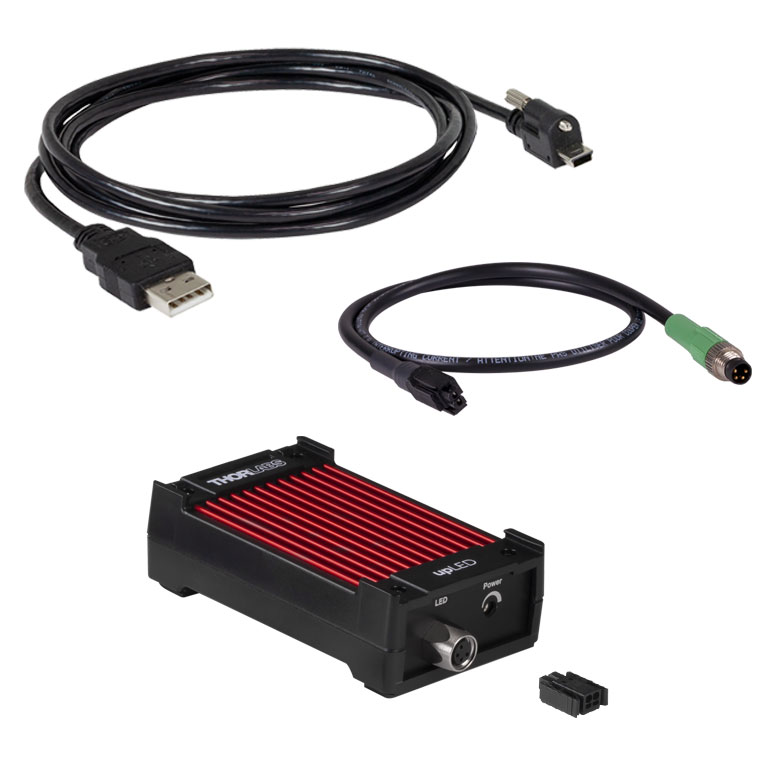
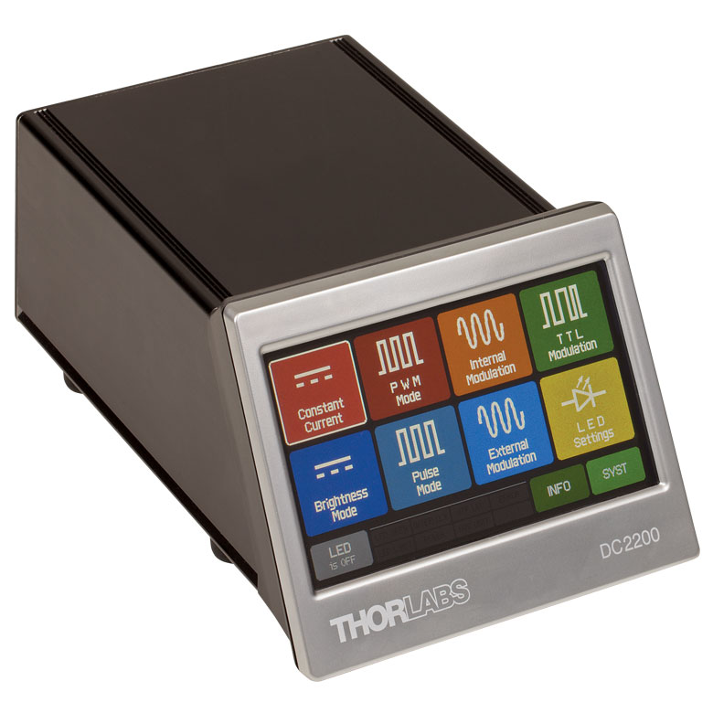
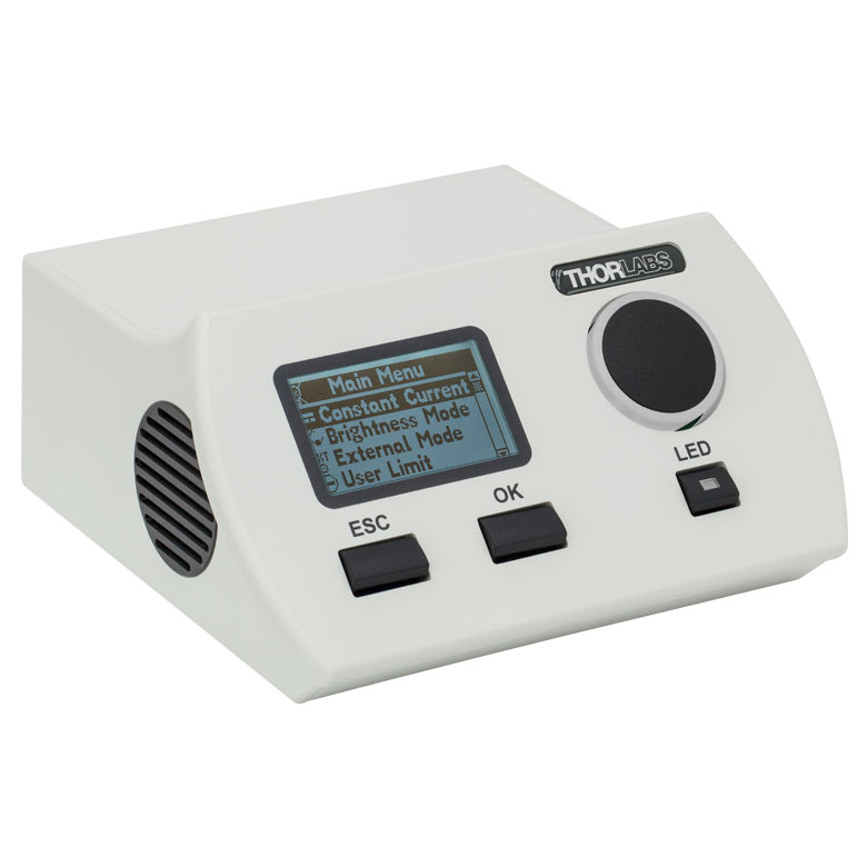
Driver Options
Thorlabs offers five drivers compatible with some or all of these LEDs: LEDD1B, UPLED, DC2200, DC4100, and DC4104 (the latter two require the DC4100-HUB). See the LED Drivers tab for a list of specifications, and the Specs tab for driver compatibility information. The UPLED, DC2200, DC4100, and DC4104 drivers are capable of reading the current limit from the EEPROM chip of the connected LED and automatically adjusting the maximum current setting to protect the LED.
Optogenetics Applications
Our fiber-coupled LEDs are ideal light sources for optogenetics applications. They feature a variety of wavelength choices and a convenient interconnection to optogenetics patch cables. Additionally, up to four different light sources can be driven and modulated simultaneously with our DC4100 controller and DC4100-HUB hub. Click here for our entire line of optogenetics products.
Patch Cable Options
These LEDs are compatible with many of our multimode fiber patch cables; see below for a list of recommended fiber patch cables for different wavelength LEDs. In addition to SMA-terminated patch cables, we also offer hybrid patch cables with an SMA connector on one end and an FC/PC connector, ferrule end, or bare fiber on the other end. Cable configurations not available from stock can be requested through our custom patch cable tool.
| Recommended Fiber and Patch Cables | ||
|---|---|---|
| LED Wavelength | Fiber Type | Stock Patch Cable |
| <350 nm | FG400AEA Ø400 µm, 0.22 NA, Solarization Resistant |
M113L SMA - SMA |
| 350 nm - 700 nm | FT400UMT Ø400 µm, 0.39 NA, High OH |
Custom Patch Cables |
| >400 nm | FT400EMT Ø400 µm, 0.39 NA, Low OH |
M28L SMA - SMA |
| M76L SMA - FC/PC | ||
| M118L SMA - Flat Cleave | ||
| M79L SMA - Ferrule | ||
| Legend | |
|---|---|
| LED Mounted to a 50 mm Long Heat Sink | LED Mounted to a 34 mm Long Heat Sink |
| Item # | Color (Click for Spectrum and Data)a |
Nominal Wavelengtha,b |
Typical Ø200 µm Core Fiber Output Powerc,d,e |
Minimum Ø400 µm Core Fiber Output Powerc,e,f |
Typical Ø400 µm Core Fiber Output Powerc,e,f |
Maximum Current (CW)c |
Forward Voltagec,e |
Bandwidth (FWHM)c,e |
Typical Lifetimec |
Recommended Driversg |
|---|---|---|---|---|---|---|---|---|---|---|
| M280F5h | Deep UV | 280 nm | 0.2 mW | 0.5 mW | 0.8 mW | 500 mA | 6.26 V | 10 nm | >1 000 h | LEDD1B, UPLED, or DC2200 |
| M300F2h | Deep UV | 300 nm | 110 µW | 320 µW | 370 µW | 350 mA | 8.0 V | 15 nm | >10 000 h | |
| M310F1h | Deep UV | 308 nm | 0.14 mW | 0.3 mW | 0.51 mW | 600 mA | 5 V | 30 nm | >10 000 h | LEDD1B, UPLED, DC2200, DC4100i, or DC4104i |
| M325F4h | Deep UV | 325 nm | 100 µW | 260 µW | 350 µW | 600 mA | 5.2 V | 12 nm | >5 000 h | LEDD1B, UPLED, or DC2200 |
| M340F4h | Deep UV | 340 nm | 0.16 mW | 0.45 mW | 0.75 mW | 600 mA | 6.6 V | 10 nm | >1 000 h | |
| M365FP1h | UV | 365 nm | 5.29 mW | 9.8 mW | 15.5 mW | 1400 mA | 3.75 V | 9 nm | >23 000 h | DC2200 |
| M375F3h | UV | 375 nm | 1.57 mW | 3.2 mW | 4.23 mW | 500 mA | 3.7 V | 9 nm | >40 000 h | LEDD1B, UPLED, DC2200, DC4100i, or DC4104i |
| M385F1h | UV | 385 nm | 2.68 mW | 9.0 mW | 10.7 mW | 700 mA | 4.3 V | 10 nm | >10 000 h | |
| M385FP1h | UV | 385 nm | 7.7 mW | 18 mW | 23.2 mW | 1400 mA | 3.65 V | 12 nm | >40 000 h | DC2200 |
| M395F3h | UV | 395 nm | 1.91 mW | 4.8 mW | 6.8 mW | 500 mA | 4.5 V | 16 nm | >10 000 h | LEDD1B, UPLED, DC2200, DC4100i, or DC4104i |
| M395FP1h | UV | 395 nm | 7.7 mW | 20.1 mW | 29.8 mW | 1400 mA | 4.0 V | 11 nm | >10 000 h | DC2200 |
| M405F3h | UV | 405 nm | 0.93 mW | 3.0 mW | 3.7 mW | 500 mA | 3.6 Vj | 12 nmj | >10 000 h | LEDD1B, UPLED, DC2200, DC4100i, or DC4104i |
| M405FP1h | UV | 405 nm | 7.7 mW | 19.3 mW | 24.3 mW | 1400 mA | 3.45 V | 12 nm | >40 000 h | DC2200 |
| M415F3h | Violet | 415 nm | 7.0 mW | 14.4 mW | 21.3 mW | 1500 mA | 3.1 V | 14 nm | >10 000 h | DC2200 |
| M430F1h | Violet | 430 nm | 2.9 mW | 5.3 mW | 7.5 mW | 500 mA | 3.66 V | 17 nm | >10 000 h | LEDD1B, UPLED, DC2200, DC4100i, or DC4104i |
| M455F3 | Royal Blue | 455 nm | 5.4 mW | 17 mW | 24.5 mW | 1000 mA | 3.5 V | 14 nm | >10 000 h | |
| M470F4 | Blue | 470 nm | 6.5 mW | 14 mW | 20 mW | 1000 mA | 3.1 V | 20 nm | >50 000 h | |
| M490F4 | Blue | 490 nm | 0.9 mW | 1.8 mW | 2.8 mW | 350 mA | 3.2 V | 26 nm | >10 000 h | |
| M505F3 | Cyan | 505 nm | 3.7 mW | 8.5 mW | 11.7 mW | 1000 mA | 3.7 V | 25 nm | >10 000 h | |
| M530F3 | Green | 530 nm | 3.2 mW | 6.8 mW | 9.6 mW | 1000 mA | 2.9 V | 30 nm | >10 000 h | |
| MINTF4 | Mint | 554 nm | 8.5 mW | 21 mW | 28 mW | 1225 mA | 3.5 V | N/A | >10 000 h | DC2200, LEDD1Bk, UPLEDk, DC4100i, or DC4104i |
| M565F3l | Lime | 565 nm | 4.4 mW | 9.9 mW | 13.5 mW | 700 mA | 2.85 V | 105 nm | >10 000 h | LEDD1B, UPLED, DC2200, DC4100i, or DC4104i |
| M590F3 | Amber | 590 nm | 1.5 mW | 3.3 mW | 4.6 mW | 1000 mA | 2.6 V | 16 nm | >10 000 h | |
| M595F2l | PC Amber | 595 nm | 4.0 mW | 8.7 mW | 11.5 mW | 1000 mA | 3.1 V | 80 nm | >50 000 h | |
| M617F2 | Orange | 617 nm | 4.4 mW | 10.2 mW | 13.2 mW | 1000 mA | 2.2 V | 15 nm | >50 000 h | |
| M625F2 | Red | 625 nm | 5.7 mW | 13.2 mW | 17.5 mW | 1000 mA | 2.2 V | 15 nm | >50 000 h | |
| M660FP1 | Deep Red | 660 nm | 4.7 mW | 10.6 mW | 15.5 mW | 1400 mA | 2.7 V | 18 nm | >1 000 h | DC2200 |
| M680F4 | Deep Red | 680 nm | 2.8 mW | 5.9 mW | 9 mW | 600 mA | 2.4 V | 20 nm | >10 000 h | LEDD1B, UPLED, DC2200, DC4100i, or DC4104i |
| M740F2 | Far Red | 740 nm | 2.1 mW | 4.1 mW | 6.0 mW | 800 mA | 2.7 V | 22 nm | >10 000 h | |
| M780F2 | IR | 780 nm | 1.15 mW | 5.5 mW | 7.0 mW | 800 mA | 2.1 V | 28 nm | >10 000 h | |
| M810F3 | IR | 810 nm | 6.1 mW | 12.7 mW | 19.3 mW | 1000 mA | 3.6 V | 30 nm | >10 000 h | |
| M850F3 | IR | 850 nm | 4.1 mW | 8.6 mW | 13.4 mW | 1000 mA | 3.2 V | 30 nm | >10 000 h | |
| M880F2 | IR | 880 nm | 0.58 mW | 2.7 mW | 3.4 mW | 1000 mA | 1.7 V | 50 nm | >10 000 h | |
| M940F3 | IR | 940 nm | 4.2 mW | 10 mW | 14.2 mW | 1000 mA | 3.8 V | 60 nm | >50 000 h | |
| M970F3 | IR | 970 nm | 2.4 mW | 5.9 mW | 8.1 mW | 1000 mA | 1.9 V | 60 nm | >10 000 h | |
| M1050F3 | IR | 1050 nm | 0.92 mW | 2.3 mW | 3.0 mW | 600 mA | 1.4 V | 37 nm | >10 000 h | |
| M1100F1 | IR | 1100 nm | 1.1 mW | 2.0 mW | 5.4 mW | 1000 mA | 1.4 V | 50 nm | >10 000 h | |
| M1200F1 | IR | 1200 nm | 0.9 mW | 1.6 mW | 2.5 mW | 1000 mA | 2.2 V | 65 nm | >10 000 h | |
| M1300F1 | IR | 1300 nm | 0.77 mW | 1.42 mW | 2.31 mW | 1000 mA | 1.7 V | 80 nm | >10 000 h | |
| M1450F1 | IR | 1450 nm | 0.44 mW | 0.86 mW | 1.34 mW | 1000 mA | 1.88 V | 95 nm | >10 000 h | |
| MBB1F1m | Broadband | 470 - 850 nmn | 0.30 mW | 0.8 mW | 1.2 mW | 500 mA | 3.6 V | 250 nm | >10 000 h | |
| MWWHF2o | Warm White | 4000 Kp | 7.9 mW | 16.3 mW | 23.1 mW | 1000 mA | 2.9 V | N/A | >50 000 h | |
| MCWHF2o | Cold White | 6200 Kp | 8.8 mW | 21.5 mW | 27.0 mW | 1000 mA | 2.9 V | N/A | >50 000 h |
LED Lifetime
One characteristic of LEDs is that they naturally exhibit power degradation with time. Often this power degradation is slow, but there are also instances where large, rapid drops in power, or even complete LED failure, occur. LED lifetimes are defined as the time it takes a specified percentage of a type of LED to fall below some power level. The parameters for the lifetime measurement can be written using the notation BXX/LYY, where XX is the percentage of that type of LED that will provide less than YY percent of the specified output power after the lifetime has elapsed. Thorlabs defines the lifetime of our LEDs as B50/L50, meaning that 50% of the LEDs with a given Item # will fall below 50% of the initial optical power at the end of the specified lifetime. For example, if a batch of 100 LEDs is rated for 150 mW of output power, 50 of these LEDs can be expected to produce an output power of ≤75 mW after the specified LED lifetime has elapsed.
Optimized Thermal Management
The thermal dissipation performance of these fiber-coupled LEDs has been optimized for stable power output. The heat sink is directly mounted to the LED mount so as to provide optimal thermal contact. By doing so, the degradation of optical output power that can be attributed to increased LED junction temperature is minimized.
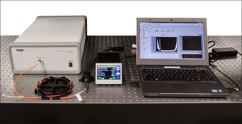
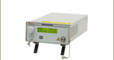
Click to Enlarge
The setup for testing the relationship between LED wavelength and current. See the table below for a complete item list.
| Item # | Description |
|---|---|
| - | Fiber-Coupled LED |
| - | SMA-to-FC/PC Fiber Patch Cable LEDs with Wavelengths ≤405 nm: Custom Cable with FG105ACA Solarization Resistant Fiber LEDs with Wavelengths >405 nm: M16L01 |
| DC2200 | High-Power LED Driver, 2 A Current Limit |
| - | Fourier Transform Optical Spectrum Analyzer |
LED Spectral Variation as a Function of Current
All LEDs will show some variation in their spectral profile and peak wavelength as a function of the drive current. For our fiber-coupled LEDs, we used an Optical Spectrum Analyzer (OSA) to track this wavelength shift as the current of the LED was increased from near zero to the maximum current.
LEDs have relatively broad, asymmetric emission profiles. The centroid wavelength of an LED is a weighted average of the wavelength across the emission profile (following a similar concept to center of mass calculations). It is defined as
where I(λ) is the intensity at each wavelength, λ. As a result, we chose to follow each LED's centroid wavelength as the current was varied in order to capture effects of both the peak wavelength shift and any changes to the overall spectral profile. The OSA's Peak Track mode will automatically calculate the centroid wavelength of a spectral peak, using a user-set lower intensity limit to determine the upper and lower limits (λ2 and λ1) of the wavelength range included in the calculation. In our case, we set the lower limit to 6 dB below the peak intensity.
For each LED, a DC2200 High-Power LED Driver was used to drive the LED over a range of preset current values. At each current value, the OSA took five scans across the LED spectrum and combined them to create an average spectrum. The OSA identified the peak wavelength by finding the highest intensity value within 50 nm of the predicted peak wavelength and then calculated a centroid wavelength as described above. Centroid wavelengths were identified every 0.05 A up to the current limit of the LED. The entire process was repeated four times for each LED. All measurements were taken with the OSA in the absolute power and high-resolution spectrometer modes (for more information on the OSA operating modes, see the full web presentation).
The results of these measurements are provided in the table below and can be viewed by clicking on the graph icons. For each LED, the centroid wavelengths over all of the runs were averaged for each current point and plotted. To give a sense of possible variation in performance, the minimum and maximum wavelengths measured at each current point over all of the experimental runs are indicated by red error bars. At the lowest current values, the LED intensity was too weak to rise above the level of the noise and provide a reasonably accurate measurement of the wavelength. In these cases, we have omitted the affected currents from the graphs.
Experimental Limitations
- Only one unit of each item # was tested. These plots are intended to provide a general sense of how the centroid wavelength changes with current and do not provide an absolute measure of the wavelength output; some variation in the centroid wavelength is expected for different LEDs with the same item #.
- The LEDs were not temperature controlled.
| Item # | Nominal Wavelength |
Max Current (CW) |
Centroid Wavelength vs. Current (Click for Plot) |
|---|---|---|---|
| M365FP1a | 365 nm | 1400 mA | |
| M375F3a | 375 nm | 500 mA | |
| M385F1a | 385 nm | 700 mA | |
| M385FP1a | 385 nm | 1400 mA | |
| M405F3a | 405 nm | 500 mA | |
| M405FP1a | 405 nm | 1400 mA | |
| M530F3 | 530 nm | 1000 mA |
| Item # | Nominal Wavelength |
Max Current (CW) |
Centroid Wavelength vs. Current (Click for Plot) |
|---|---|---|---|
| M595F2 | 595 nm | 1000 mA | |
| M617F2 | 617 nm | 1000 mA | |
| M625F2 | 625 nm | 1000 mA | |
| M740F2 | 740 nm | 800 mA | |
| M780F2 | 780 nm | 800 mA | |
| M880F2 | 880 nm | 1000 mA |
| Pin | Specification | Color |
|---|---|---|
| 1 | LED Anode | Brown |
| 2 | LED Cathode | White |
| 3 | EEPROM GND | Black |
| 4 | EEPROM IO | Blue |

Pin Connection
The diagram to the right shows the male connector of the fiber-coupled LED assembly. It is a standard M8 x 1 sensor circular connector. Pins 1 and 2 are the connection to the LED. Pins 3 and 4 are used for the internal EEPROM (electrically erasable programmable read-only memory) in these LEDs. If using an LED driver that was not purchased from Thorlabs, be careful that the appropriate connections are made to Pin 1 and Pin 2 and that you do not attempt to drive the LED through the EEPROM pins.
To fully support the maximum optical power of the LED you intend to drive, ensure that the max voltage and max current of the driver are equal to or greater than those of the LED.
| Compatible Drivers | LEDD1B | UPLEDa | DC2200a | DC4100a,b | DC4104a,b |
|---|---|---|---|---|---|
| Click Photos to Enlarge |  |
 |
 |
 |
 |
| LED Driver Current Output (Max)c | 1.2 A | 1.2 A | LED1 Terminal: 10.0 A LED2 Terminal: 2.0 Ad |
1.0 A per Channel | 1.0 A per Channel |
| LED Driver Forward Voltage (Max)e | 12 V | 8 V | 50 V | 5 V | 5 V |
| Modulation Frequency Using External Input (Max) | 5 kHz | - | 250 kHzf,g,h,i | 100 kHzg,h,i (Simultaneous Across all Channels) |
100 kHzg,h,i (Independently Controlled Channels) |
| External Control Interface(s) | Analog (BNC) | USB 2.0 | USB 2.0 and Analog (BNC) | USB 2.0 and Analog (BNC) | USB 2.0 and Analog (8-Pin) |
| Main Driver Features | Very Compact Footprint 60 mm x 73 mm x 104 mm (W x H x D) |
USB-Controlled | Touchscreen Interface with Internal and External Options for Pulsed and Modulated LED Operation | 4 Channelsb | 4 Channelsb |
| EEPROM Compatible: Reads Out LED Data for LED Settings | - | ||||
| LCD Display | - | - |
| Posted Comments: | |
Thibaut Moulin
(posted 2024-03-20 13:28:33.177) Hi, i have a M590F3 source. I am interested of the shift wavelength for this source. I hav read the graphic for M595F2 beacause this source is near in term of wavelenght. It seems there is a mistake with the graphic because the waveleght value do not correspond to the M595F2 source. hchow
(posted 2024-03-21 04:43:30.0) Dear Mr. Moulin, thank you for your feedback. I do see the confusion now. I have checked the test reports of the M590F3 and M595F2, and they do correspond to the peak wavelengths at 590 nm and 595 nm. I apologise for the confusion on the raw data and the spectrum graph shown on our webpage. We will get it changed ASAP. kim bumjin
(posted 2024-03-11 12:07:56.247) hello. I want to make a collimated LED light source for RGB (455, 520, 625nm - not fixed) with a beam size of less than 5mm. Can you recommend a light source and collimating optics? Suvvi K N
(posted 2023-10-27 11:53:57.63) Hi,
I recently purchased
MCWHF2, 6200K, Cold white LED from thorlabs. I only used it couple of times and the LED seems to not working now. I did pay attention to the current and was kept within the requirement mentioned in the data sheet.
I also did try to check inside this LED and I think that the metal core LED is damaged and needs to be replaced. Could you please provide some assistance as how to achieve this? Is it possible to purchase single metal core PCB LED compatible with this
MCWHF2 light source from you and replace it by ourselves?
Or do we need to ship it back to you for replacing it. The device was purchased in July 2023 for your reference.
Thanks in advance hchow
(posted 2023-11-02 09:46:51.0) Dear Suvvi K N, thank you for your enquiry. It is unfortunate that your device is not functioning as it should. I will personally reach out to you via E-mail to see how we can assist you. Thank you. user
(posted 2023-06-16 10:21:09.057) I want to buy MBB1F1,but I wonder how its power / luminance acts as time and current changes. jweimar
(posted 2023-06-22 02:10:02.0) Thank you very much for your inquiry. You can find additional information about the power/ time dependence by clicking the “Stability” tab on the product page. We will reach out to you directly to share the plots with you. user
(posted 2023-05-23 15:25:47.87) Hi Thorlabs,
I use the M1050F3 in combination with a M91L01 fiber (200 micron core). I measure only 220uW after the fiber instead of the expected 900uW. Do you see anything, I can try to improve that?
Thanks! hchow
(posted 2023-05-24 05:50:16.0) Dear User, thank you for your feedback. I am sorry to hear that you are not getting the output optical power you are expecting from our products. I will personally reach out to you to see how best to solve your problem. Thank you. 斌 赵
(posted 2023-04-14 22:26:52.843) Light source stability is too poor, can be repaired hchow
(posted 2023-04-17 09:32:50.0) Dear Mr. 斌 赵 , thank you for your feedback. I am sorry to hear that you are experiencing problems with your fiber coupled LED. But not to worry, I am here to help. I will personally reach out to you to rectify this problem. Thank you. user
(posted 2023-03-13 10:26:55.243) The axis labels for the spectrum in the spec sheet are swapped. fmortaheb
(posted 2023-03-16 11:17:08.0) Thank you very much for your feedback. We will correct it as soon as possible. Biswaranjan Behera
(posted 2023-03-09 14:27:40.49) Can this be operated using a pulser with a short pulse duration? wskopalik
(posted 2023-03-14 05:01:21.0) Thank you very much for your feedback!
These fiber-coupled LEDs can be operated in a pulsed or modulated mode as well.
I will contact you directly so we can see if your requirements can be achieved with these LEDs. Dirk Hoenig
(posted 2022-03-01 12:14:57.417) Hello Thorlabs,
the specs datasheets of the fiber coupled LEDs state: "Optical power increases proportionally with the core diameter and nearly proportionally to the square of the NA."
Why is that so instead of being proportional to the core area (thus diameter squared)?
Best regards
Dirk wskopalik
(posted 2022-03-16 09:20:03.0) Thank you very much for your feedback!
It depends on the dimensions of the LED emitter compared to the fiber core if the power increases proportional with the core diameter or proportional with the square of the core diameter, i.e. the core area. For these fiber-coupled LEDs, the emitter is in most cases larger than the used fibers so the power is usually proportional with the core area. We will check and correct the statement in the spec sheets.
Please note however that this proportionality should only be considered a rule of thumb. There may be deviations from this proportionality between different fibers due to the fiber type, OH content in the fiber, NA of the fiber, etc.
I have also contacted you directly to discuss this in more detail. M. H.
(posted 2022-02-18 02:49:06.78) Hello,
I would like to know if it is possible to run the LED's with more current if I provide enough cooling.
I would like to use one of these LEDs to create a homogeneous illumination over a Square Core fiber (150x150um). But I need a power >10mW at the fiber output at a wavelength between 450-530nm.
Thanks dpossin
(posted 2022-02-21 05:21:51.0) Dear customer,
Thank you for your feedback. We generally do not recommend to increase the current over the specified maximum as this can lead to reduced lifetime or damage. However the optical output power can be increased by using a fiber with a larger core diameter. For example the output from M780F1 has been increased by a factor of around 5 by using a 1000µm core fiber (M30L02). I am reaching out to you in order to discuss this in more detail. user
(posted 2021-08-07 01:24:01.76) Hello, I would like to know the coherence length of led source MWWHF2. Thank you YLohia
(posted 2021-08-06 04:59:53.0) Hello, thank you for contacting Thorlabs. LEDs are incoherent sources, so we cannot spec or measure a coherence length for these. user
(posted 2020-12-15 04:03:29.49) Hello, I am looking for a fiber-coupled white-light LED with more output power than the 23.1 mW of the MWWHF2. Do you have something like that? Or would it be possible to use a multi-mode fiber with a core diameter > 400 µm to increase the power further? Thanks in advance and best regards. MKiess
(posted 2020-12-15 10:39:43.0) Thank you very much for your inquiry.
If you use a fiber with a larger core diameter and a larger NA, this will lead to higher optical output powers at the fiber output. We recommend using multimode (MMF) fiber with the MWWHF2. Optical output power is specified for a Ø400 μm MMF with an NA of 0.39 at the maximum allowed LED current. Optical power increases proportionally with the core diameter and nearly proportionally to the square of the NA.
I have contacted you directly to discuss further details. Naveen Tangri
(posted 2020-10-23 16:05:09.817) Hello,
We're located in Santa Clara, California and we're looking for OEM quantities of broadband unmounted SMT LEDs for embedded applications. We looked at your LEDSW50 but its spectral power distribution curve is too "wavy gravy". However, the LED used in your MBB1F1 appears to have a flatter and more uniform spectral curve.
So here's the question...would Thorlabs be willing to sell just the LED used in your MBB1F1? We'd be open to signing some sort of "non-compete" agreement, if required.
Sorry for the oddball question, and "no" would be a perfectly acceptable response, but we wanted to know either way.
Thanks and best regards! MKiess
(posted 2020-10-27 07:01:49.0) Dear Naveen, thank you very much for your inquiry. The right LED for your application in this case is probably the MBB1D1. This broadband LED ranging from 470nm to 850nm and has a relatively flat spectral emission over this wavelength range. Furthermore, this is the pure LED on a metal core PCB.
I have contacted you directly to discuss further details. John Keech
(posted 2019-11-20 16:36:43.507) What is the laser safety rating of LED fiber coupled sources? Are they safety rated in this way?
https://www.thorlabs.com/newgrouppage9.cfm?objectgroup_ID=5206
Thank you,
John Keech
Corning Inc. MKiess
(posted 2019-11-22 10:32:04.0) This is a response from Michael at Thorlabs. Thank you very much for the inquiry. These LEDs are classified in risk groups according to the International Standard "Photobiological Safety of Lamps and Lamp Systems" IEC 62471. This is different depending on the desired LED. The exact risk group of the individual LEDs can be found in the LED specification sheet, which can be downloaded on our webpage, in the Warnings and Safety section. marcin.bartosik
(posted 2018-08-10 14:08:50.093) Hello!
Could you please let me know if the MCWHF2 can be powered by a 12V DC from a 280W power supply?
Have a nice day,
Marcin swick
(posted 2018-08-13 05:12:19.0) This is a response from Sebastian at Thorlabs. Thank you for the inquiry.
Basically it is possible to drive our LEDs with constant voltage sources.
In order to drive the MCWHF2 with a constant voltage you need to limit the current to 1 Ampere. I contacted you directly to provide further assistance. edwin.walker.ctr
(posted 2017-10-11 19:52:36.64) using the M780F2 780 nm, 5.5 mW (Min) Fiber-Coupled LED, with LEDD1Ba driver, what is the output power stability %rms? is it 5%rms variation or 10%rms output power variation wskopalik
(posted 2017-10-19 10:03:13.0) This is a response from Wolfgang at Thorlabs. Thank you very much for your inquiry.
The driver LEDD1B is specified with a current ripple of 8mA. This ripple could also be seen in the light emission of the LED. The M780F2 has a max current of 800mA so this would correspond to 1% variation.
The LED itself will show a decrease in power during operation which would depend e.g. on the current and on the ambient temperature. This decrease is typically in the range of 3-5%. When the LED is switched on, there might also be some short term overshoots due to the driver or due to temperature changes. Other variations are not expected.
I will contact you directly to talk about your requirements in more detail. fmor82
(posted 2015-11-25 16:38:00.073) To Whom It May Concern:
I am writing to ask you something about the cable used to power the LED (M385FP1).
I would like to know how many wires you have inside this cable.
Thank you in advance,
Flavio Mor. shallwig
(posted 2015-11-26 03:58:45.0) This is a response from Stefan at Thorlabs. Thank you very much for your inquiry. There are 4 wires inside the cable of our fiber coupled LEDs. In the “Pin Diagram” tab on the website you can find the pin assignment information : http://www.thorlabs.com/newgrouppage9.cfm?objectgroup_id=5206&pn=M385FP1#5262
The connector we use is a standard M8 x 1 sensor circular connector. I will contact you directly to check if you have any further questions. user
(posted 2015-09-01 15:52:41.237) Yes, I understand that now the fiber which you use is 200 um and 0.22NA. The thing which I don't understand is that the coupled light is the same that with the other of 0.39NA. It is supposed that it would be less the coupled light with 0.22NA than 0.39NA, but you haven't change any value, so I'm a bit confused. I thought that with 0.22NA the coupled light will be 3.14 times less than with 0.39NA.
William shallwig
(posted 2015-09-02 02:11:40.0) This is a response from Stefan at Thorlabs. Thank you again for your inquiry. The values from the website did not change since we never measured them with a 0.39NA fiber, they were always measured with a 200 µm core 0.22NA fiber. 0.39NA was a typo in the specs which we revised. Maybe we can discuss this by email. Since you left no contact data, could you please contact me at europe@thorlabs.com. Thank you. user
(posted 2015-09-01 13:32:41.34) Hello,
Last month I started to see Thorlabs light sources, and to see their technical characteristics to make a purchasment for my univerity laboratory.
Today, I come back from holidays, and I see that some changes have taken place, you have change the fiber characteristics for fiber coupled light power.
Last month, they were a fiber of 400 um and 0.39 NA and other of 200 um and 0.39 NA, but today the 200 um fiber has 0.22NA.
I'm surprised that the light coupled power values doen't change in any case because I thought that it depends of fiber characteristics.
Since I know, the coupled light must be 3 times less in 0.22NA case compared with 0.39NA case.
William shallwig
(posted 2015-09-01 09:01:41.0) This is a response from Stefan at Thorlabs. Thank you very much for your inquiry. The power values were always tested with a 200µm 0.22NA fiber (FG200UCC). The numerical aperture NA 0.39 was a typo which we removed. casey.donaher
(posted 2015-07-15 15:13:09.613) Just noticed that the spec sheet for M617F1 says max 1000mA, but the DC2100 sets its max to 700mA when the M617F1 is plugged into it.
One or the other is wrong. One the plus side, the other is right (maybe.) shallwig
(posted 2015-07-16 07:01:23.0) This is a response from Stefan at Thorlabs. Thank you very much for your inquiry. The maximum current which can be applied to this LED is as stated in the spec sheet 1000mA. In the manual of the DC2100 on page 14 http://www.thorlabs.com/thorcat/18300/DC2100-Manual.pdf it is described how the user Limit current can be changed. I guess you could not change this current to 1000mA for your M617F1. In this case there is most likely a wrong value written to the LEDs EPROM. I will contact you directly to troubleshoot this in more detail. cilveti.ander.92
(posted 2015-03-19 16:51:17.157) Hi, I was looking the M420F2 coupled light source to purchase it, because his great coupled power, 8.9 mW in 200um fiber. But then I read the datasheet, and I look that there puts that the minimun power coupled in a 400um fiber is also 8.9 mW... It is also strange that in others light sources usully the power coupled in 400un core fiber is 4 times bigger than in 200um(for example M365F1 200um:1mW and 400um:4.1 mW), but in 420nm case is less than 2(200um:8.9mW and 400um:16.2 mW).
So the question is, is really that the power coupled in 200um fiber is 8.9 mW??or is another value?? shallwig
(posted 2015-03-20 06:54:48.0) This is a response from Stefan at Thorlabs. Thank you very much for your inquiry. The specifications as stated on the website for these LEDs were measured and are correct so far. The assumption by increasing the core diameter and NA to increase the power proportionally does not take into account that each LED type has a different size and viewing angle (directional characteristic) which also influence the coupling efficiency.
All the numbers we provide on the web and in the datasheets are based on real measurements. We always treat the measurements quite conservative which means that we reduce the results typically by 10%. We measure up to 5 different LEDs with 5 different patch cords. Then we take the average and the minimum value and reduce it by 10% for our specs. By accident for this specific LED the minimum power with a 400µm fiber is nearly the same as the typical output power with a 200µm fiber.
The typical output power you can expect with a 200µm fiber is indeed 8.91mW. I will contact you directly to check if you need any further information. andisetiono
(posted 2015-02-25 03:13:43.507) I want to know, Is power cable included to the product? thank you tschalk
(posted 2015-02-25 07:22:06.0) This is a response from Thomas at Thorlabs. Thank you very much for your inquiry. The power cable is attached to the fiber coupled LED. Please note that you need an additional LED controller to drive the unit. Therefore you can use a DC2100 or a LEDD1B. user
(posted 2014-02-03 17:09:20.777) Hello, are these continuous wave sources? tschalk
(posted 2014-02-04 02:25:49.0) This is a response from Thomas at Thorlabs. Thank you very much for your inquiry. These LEDs are compatible with our LED drivers LEDD1B, DC2100 and DC4100 which can be found here: https://www.thorlabs.com/navigation.cfm?guide_id=2109. With all drivers the LEDs can be used as a continuous wave source. It is also possible to use the modulation input of each driver and to use the LEDs as a pulsed source. The DC2100 provides also Pulse Width Modulation Mode which can be used without an external Modulation source. Please contact me at europe@thorlabs.com if you have any further questions. kcs32
(posted 2013-12-19 11:42:49.89) Hello,
I'm curious about the long power/EEPROM cable shown on the back of the fiber coupled LED. Is this cable permanently attached to the back of the device, or can it be removed? This is not obvious from the pictures and drawings I've seen.
Can to CON8ML-4 mating connector be plugged directly into the device instead of at the end of this cable? I'm thinking of using these LED's in a small volume, portable device, so minimizing the space taken up by the long cable would be very helpful. Thank you tschalk
(posted 2013-12-20 08:49:48.0) This is a response from Thomas at Thorlabs. Thank you very much for your inquiry. The cable is permanently attached to the LED so it can not be replaced by the CON8ML-4. We can offer you a device with a shorter cable and i will contact directly with more detailed information. carlos.paladini
(posted 2013-11-21 19:31:52.507) It seems that the M625F1 has a peak intensity actually at about 635 nm and the M617F1 has a peak at about 625 nm on the spectrum pop-up window. Is this correct? I would like an LED with peak intensity at 625 nm but am confused by the name of the LED and its stated peak light intensity. In other words, which LED actually delivers peak light intensity at 625 nm, the M617F1 or the M625F1?
Thanks tschalk
(posted 2013-11-25 06:47:50.0) This is a response from Thomas at Thorlabs. Thank you very much for your inquiry. For our visible LEDs the so called "dominant wavelength" is given and this specification takes the sensitivity of the human eye into account. The spectra provided on our homepage are correct and if you need a peak wavelength of 625nm the M617F1 would be the right choice. joerg.koenig
(posted 2013-10-10 19:53:13.937) Hi, what is the spectral power density [W/nm] of the MWWHF1 using a 400 µm core fiber? tschalk
(posted 2013-10-15 05:10:00.0) This is a response from Thomas at Thorlabs. Thank you very much for your inquiry. Unfortunately we can not provide the spectral power density of this light source. It is also depending on which fiber you are using. I will contact you directly to discuss your application. jlow
(posted 2012-09-26 09:52:00.0) Response from Jeremy at Thorlabs: The 5.1mW is the typical output power when using a Ø400µm core fiber with 0.39 NA with 1000mA drive current. When a larger core fiber such as the M35L0x (Ø1000µm, 0.39NA) is used, the coupling efficiency from the LED to the fiber is increased, hence the 17.61mW min. power. tpth
(posted 2012-09-26 09:27:45.0) Dear Sir:
I have a question:
Why the mininmum power 17.61mW (in a table)can be obtained when you use 530nm LED with a fiber M35L0x, though input power is 5.1mW?
I need a precise estimation of the amount of decrease in LED power during propagating in a fiber.
Please let me know the correct answer before my order.
Best regards.
Tsutomu Hoshimiya,
Prof. Tohoku Gakuin University jvigroux
(posted 2012-06-06 11:13:00.0) A response from Julien at Thorlabs: Thank you for your inquiry! There will always be a trade-off to be found between fiber diameter and/or NA (ie. beam quality) and optical power coupled into the fiber. When using a fiber having a NA of 0.39, the focal length for the collimation lens to be used should be about 1mm. The beam quality that would however result from the combined effect of such a short focal length and the fiber diameter would lead to quite high divergence. In you case, I would recommend using a somewhat longer focal length for the collimation lens and subsequently a beam expander for the beam diameter reduction. I will contact you to discuss further the exact requirements of your setup to find what the most suited solution would be. igkiou
(posted 2012-06-06 04:37:26.0) Hi, I am interested in creating a very collimated white beam of diameter < 0.8 mm. MCWHF1 provides enough output power when used with the fiber you used for your tests, a MM 400 um 0.39 NA fiber. What would you recommend using for collimation of the output of this combination? Would you recommend any of your prepackaged collimators? Thank you in advance for your assistance. tcohen
(posted 2012-05-14 09:18:00.0) Response from Tim at Thorlabs: Thank you for your interest in our products. Our sales department will contact you to provide you with an official quote. emlee1
(posted 2012-05-13 12:32:44.0) I am interested to purchase this product. Can you email me the quotation for this product and a suitable power supply for use in Singapore? Do include shipping to Singapore as well in your quote. Thanks. jvigroux
(posted 2012-02-06 13:00:00.0) A response from Julien at Thorlabs: thank you for your inquiry! Unfortunately, as of now, there is no LED available with a high enough power in the wavelength range. I will ocntact you to know your exact requirement sin order to see which alternative there could be. kforsyth
(posted 2012-02-06 11:37:11.0) Any plans for going shorter in wavelength soon, say to 250 - 300 nm? jvigroux
(posted 2011-12-15 10:17:00.0) A response from Julien at Thorlabs: I just measured the coupled power in a 460HP fiber from a MCWHF1. The output power out of the fiber was around 50nW. In comparison, a 400µm 0.39NA fiber would yield an output power of around 7mW. jvigroux
(posted 2011-12-14 11:52:00.0) A response from Julien at Thorlabs: thank you for your inquiry! We do not have the value yet but I will perform the measurement by tomorrow and let you know the obtained value. doerr
(posted 2011-12-14 17:22:01.0) Hi,
I need a white light source coupled to a single-mode fiber. I've tried with regular halogen bulbs, but the output power is at least 10 times to low. The white light LED would be an option, even though the spectral distribution is not optimal. Can you give me any numbers what coupling efficiency or output power I can expect from a LED coupled to a single-mode fiber? Fiber type would be the same as with the 460HP patch cords. jvigroux
(posted 2011-08-29 12:21:00.0) A response from Julien at Thorlabs: thank you for your feedback. We are in the process of measuring the power coupled into different standard fibers using the fiber coupled LEDs. Before publishing those values however, the tests have to be ran until the end and critically assessed. I will contact you directly per email in order to discuss with you the values that can be expected for your configuration. rhs
(posted 2011-08-22 12:50:51.0) I miss some guidelines for choosing the optimal delivery fiber. Your measurement data has been obtained using a 400µm/0.4NA MM fiber, but that doesnt say much about the performance when using a different fiber.
It would be extremely helpful to have just two graphs showing the spatial distribution and the angular distribution of intensity at the coupling plane.
Thank you. jjurado
(posted 2011-08-05 09:30:00.0) Response from Javier at Thorlabs to last poster: Thank you very much for your feedback!The mounts for these fiber-coupled LEDs have been designed to accept for M6 and 1/4" diameter screws. We will take a look at our current units to make sure that both screws fit and will make changes if it turns out that 1/4" screws are not compatible. Regarding the marking of the center wavelength, there is actually an identification label on the back side of the device with the part number of the LED, which calls out the center wavelength (with the exception of the MCWHF1 cold white LED). Please contact us at techsupport@thorlabs.com if you have any further questions or comments. user
(posted 2011-08-02 18:32:35.0) The mounting slots are designed for M6 screws and dont pass 1/4" screws that are used in the USA.
It would also be nice to have the center wavelength engraved on the housing, either on the front surface, or on the top edge. |
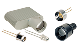
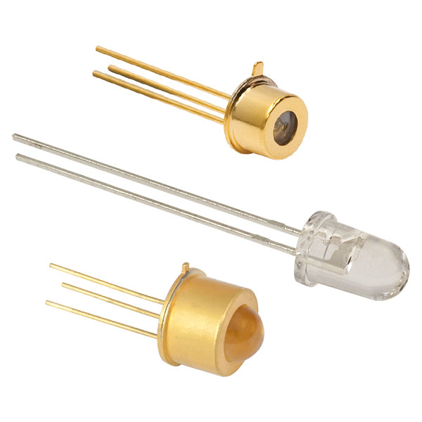
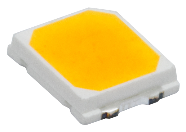
This tab includes all LEDs sold by Thorlabs. Click on More [+] to view all available wavelengths for each type of LED pictured below.
| Light Emitting Diode (LED) Selection Guide | ||||||
|---|---|---|---|---|---|---|
| Click Photo to Enlarge (Representative; Not to Scale) |
 |
 |
 |
 |
 |
 |
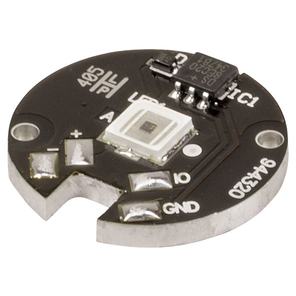
| Type | Unmounted LEDs | Pigtailed LEDs | LEDs in SMT Packages |
LED Arrays | LED Ring Light | Cage-Compatible Diffuse Backlight LED |
| Light Emitting Diode (LED) Selection Guide | ||||||
|---|---|---|---|---|---|---|
| Click Photo to Enlarge (Representative; Not to Scale) |
 |
 |
 |
 |
 |
 |
| Type | PCB- Mounted LEDs |
Heatsink- Mounted LEDs |
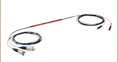
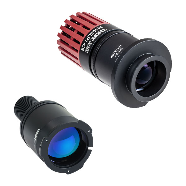
Collimated LEDs for Microscopyb | Fiber- Coupled LEDsc |
High-Power LEDs for Microscopy | Multi-Wavelength LED Source Optionsd |

 Zoom
Zoom
Click to Enlarge
M365FP1, M385FP1, M395FP1, M405FP1, and M660FP1 are each mounted to a 50 mm long heat sink.
- Integrated EEPROM for Automated LED Settings with Compatible Thorlabs Controllers
- Long Lifetimes >10 000 Hours (Except M280F5, M325F4, M340F4, and M660FP1; See Specs Tab for Details)
- Output can be Modulated with Suitable Controller (See LED Drivers Tab)
- Stable Output Intensity by Optimized Thermal Management
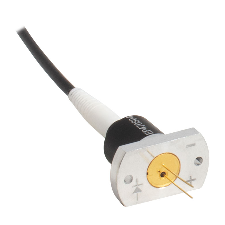
- Accepts SMA Fiber Connector
These fiber-coupled LEDs each consist of an LED mounted to a heat sink with an SMA fiber bulkhead. They can be easily integrated into an optical setup using one of our SMA-terminated multimode fiber patch cables. When the patch cable is connected to the SMA bulkhead on the LED housing, the LED will be butt-coupled to the SMA fiber connector. Hybrid patch cables can be used to transition from an SMA connector to an FC/PC connector, ferrule end, or bare fiber. For compatible drivers to power these LEDs, please see the LED Drivers tab. Please note that the minimum output powers specified below apply when the LED is used with a Ø400 µm core multimode fiber patch cable.
For applications where a hybrid patch cable is not practical, we can configure these fiber-coupled LEDs with FC/PC bulkheads; contact Tech Support for details.

 Zoom
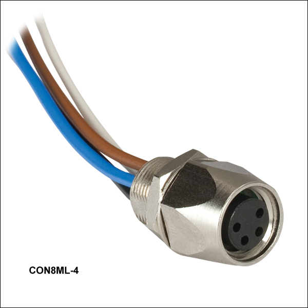
Zoom- Female 4-Pin Pico (M8) Receptacle
- M8 x 1 Thread for Connection to Mounted LED Power Cable
- M8 x 0.5 Panel-Mount Thread for Custom Housings
- 0.5 m Long, 24 AWG Wires
- IP 67 and NEMA 6P Rated
The CON8ML-4 connector can be used to mate mounted LEDs featured on this page to user-supplied power supplies. We also offer a male 4-Pin M8 connector cable (item # CAB-LEDD1).
| Pin | Color | Specification | 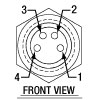 |
|---|---|---|---|
| 1 | Brown | LED Anode | |
| 2 | White | LED Cathode | |
| 3 | Black | EEPROM GND | |
| 4 | Blue | EEPROM IO |
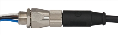
CON8ML-4 Shown Connected to the 4-Pin M8 Plug of Mounted LED