 Products Home
LEDs on Metal-Core PCBs
- UV, Visible, IR, and Mid-IR Models Available
- LED Mounted on Metal-Core Printed Circuit Board
- Ideal for OEM Applications
M340D4
340 nm LED,
≥45.5 mW Power Output
M1300D3
1300 nm LED,
≥122.8 mW Power Output
M565D2
565 nm LED,
≥880 mW Power Output


Please Wait
Features
- Nominal Wavelengths Ranging from 265 nm to 5200 nm
- White, Dual-Peak, and Broadband LEDs Also Available
- Minimum Outputs Ranging from 0.8 mW to 2118.1 mW
- LED Mounted on Metal-Core Printed Circuit Board for Excellent Heat Management
- Long Lifetimes (See Tables Below for Details)
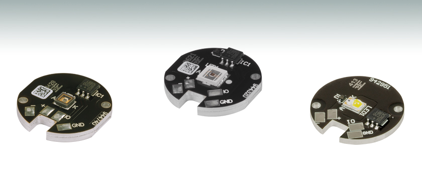
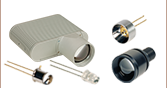
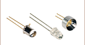
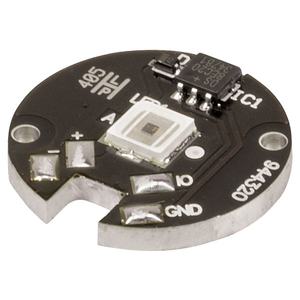
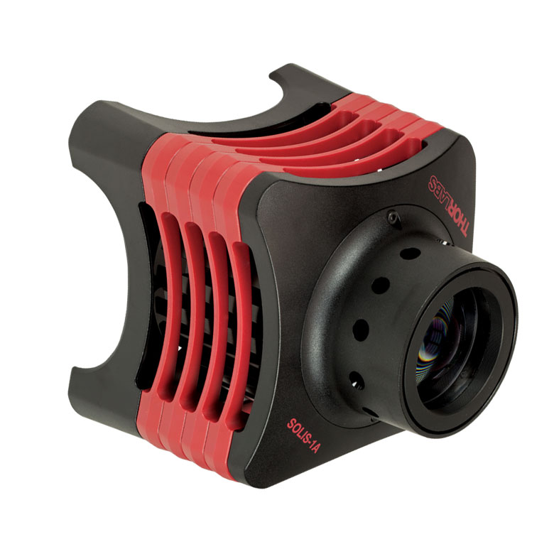
Thorlabs' LEDs on Metal-Core Printed Circuit Boards (MCPCBs) are designed to provide high-power output in a compact package. Each LED package consists of a single LED that has been soldered to an MCPCB. These LEDs are ideal for OEM or custom applications; they should not be used for household illumination.
Thorlabs uses high-thermal-conductivity MCPCB materials. The MCPCB is designed to provide good thermal management. However, the LED must still be mounted onto an appropriate heat sink using thermal paste to ensure proper operation and to maximize operating lifetime. Mounting holes are provided on the MCPCB surface for attaching the LED to a heat sink; the Ø2 mm through holes are compatible with #1 (M2) screws (not included).
The spectrum of each LED and complete specifications can be viewed by clicking on the info icon (![]() ) for each LED below for details. Multiple windows can be opened simultaneously in order to compare LEDs.
) for each LED below for details. Multiple windows can be opened simultaneously in order to compare LEDs.
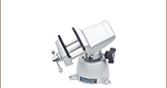
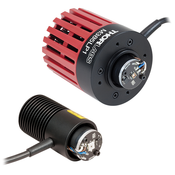
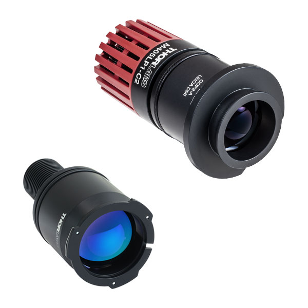
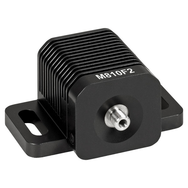
Thorlabs also offers mounted LEDs with an integrated heat sink, as well as collimated mounted LEDs, which are compatible with microscopes from major manufacturers. For fiber applications, we also offer fiber-coupled LEDs. For questions on choosing an appropriate LED and to discuss mounting requirements, please contact Tech Support.
Optimized Thermal Management
These LEDs possess good thermal stability properties; hence, degradation of the optical output power due to increased LED temperature is not an issue when the LED is properly mounted to a heat sink using thermal paste, thermal epoxy, or thermally conductive double-sided tape.
White Light, Dual-Peak, and Broadband LEDs
Our warm, neutral, and cold white LEDs feature broad spectra that span several hundred nanometers. The difference in appearance amongst these three LEDs can be described using the correlated color temperature, which indicates that the LEDs color appearance is similar to a black body radiator at that temperature. In general, warm white LEDs offer a spectrum similar to a tungsten source, while cold white LEDs have a stronger blue component to the spectrum; neutral white LEDs provide a more even illumination spectrum over the visible range than warm white or cold white LEDs. Cold white LEDs are more suited for fluorescence microscopy applications or cameras with white balancing, because of a higher intensity at most wavelengths compared to warm white LEDs. Neutral white LEDs are ideal for horticultural applications.
For horticultural applications requiring illumination in both red and blue portions of the spectrum, Thorlabs offers the MPRP1D2. This purple LED features dual peaks at 455 nm and 640 nm, respectively, to stimulate photosynthesis (see graph to compare the absorption peaks of photosynthesis pigments with the LED spectrum). The LED was designed to maintain the red/blue ratio of the emission spectrum over its lifetime to provide high uniformity of plant growth.
The MBB1D1 broadband LED has a relatively flat spectral emission over a wide wavelength range. Its FWHM bandwidth ranges from 500 nm to 780 nm, while its 10 dB bandwidth ranges between 470 nm and 940 nm. The MBB2D1 broadband LED features a spectrum with peaks at approximately 770 nm, 860 nm, and 940 nm.
Soldering
These LEDs have been soldered to a metal core with low thermal resistance. While this feature allows for good thermal management, it can also prevent the metal pads from reaching the appropriate temperature for soldering when the package is connected to a heat sink. To properly solder wires to the pads, first make sure that the metal core is not in contact with a heat sink or a metal surface. We recommend using a small vise or similar device to hold the MCPCB during the soldering process and wires with a minimum gauge of 24 AWG (0.25 mm2).
To solder wires to the MCPCB, first hold the copper bit of the soldering iron on one of the pads for approximately 30 seconds using a soldering temperature of about 350 °C. The soldering iron will heat the entire metal-core PCB, so do not touch the LED package until it has cooled down after the soldering process. Test the temperature by touching tin solder to the pad: the solder will melt and flow evenly over the entire pad at the correct temperature. Coat the other pads with tin solder. Now, solder the wires to the pads. Use tweezers or pliers to remove the MCPCB from the vise and place it on a heat sink or metal surface. The metal-core PCB will cool down in several seconds and is now ready for your application.
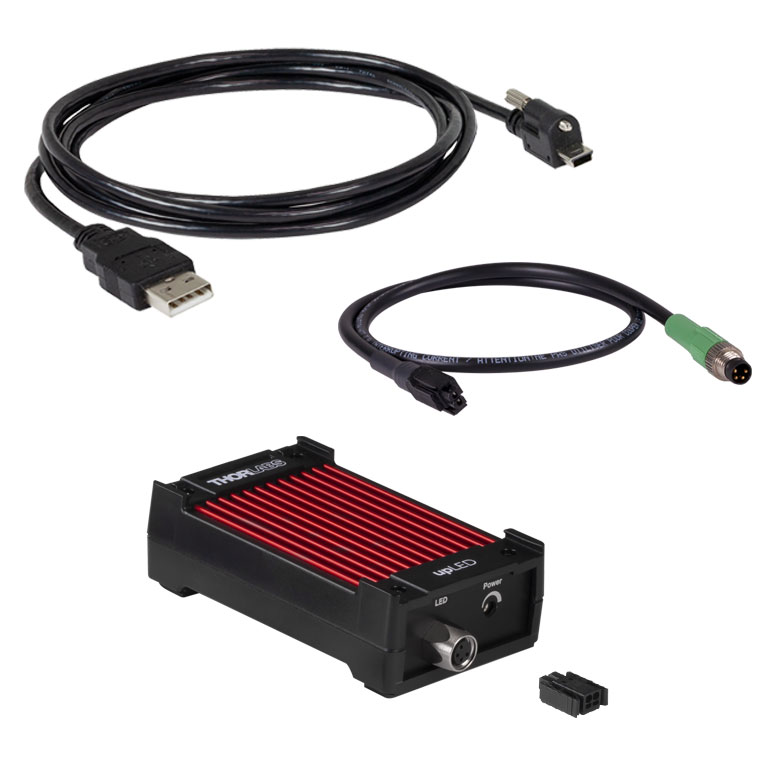
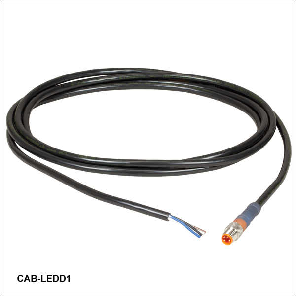
For convenient connection of the LEDs to the drivers listed on the LED Drivers tab, please order the optional CAB-LEDD1 LED connection cable below.
Driver Options and Pin Assignments
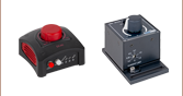
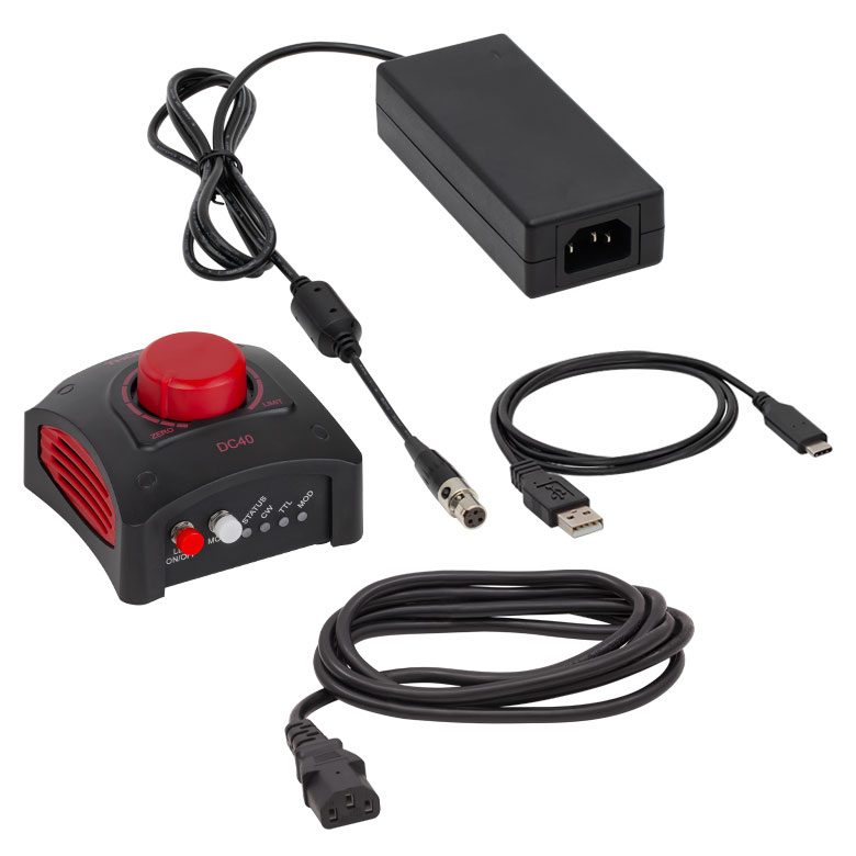
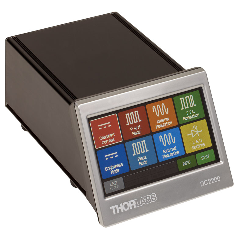
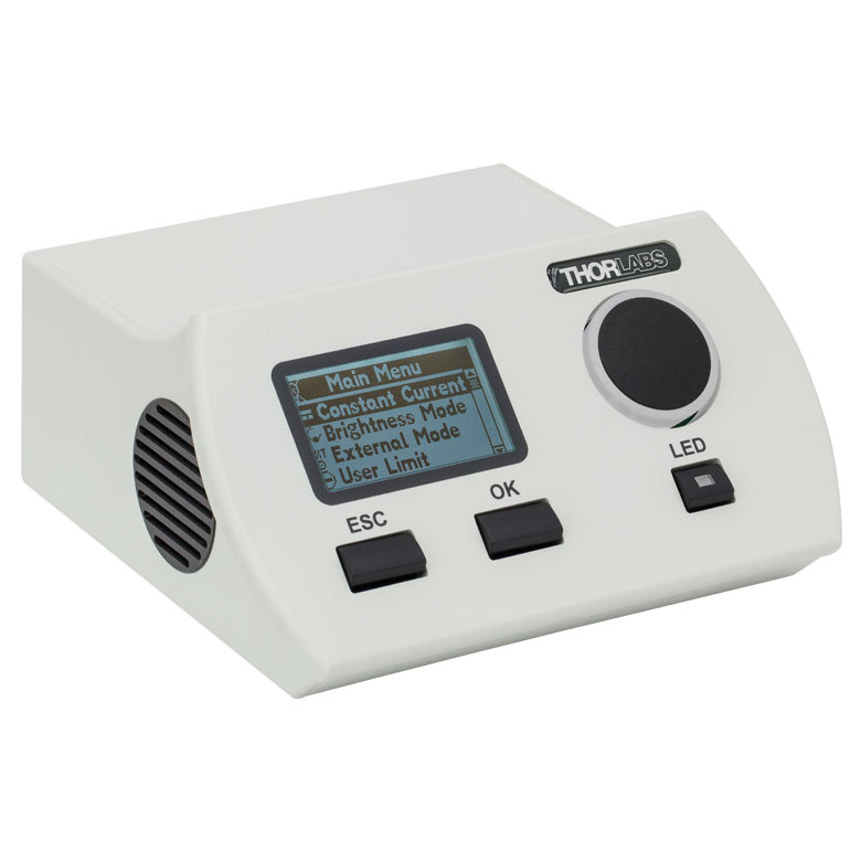
Thorlabs offers six drivers compatible with some or all of these LEDs: LEDD1B, UPLED, DC40, DC2200, DC4100, and DC4104 (the latter two require the DC4100-HUB). See the LED Drivers tab for compatibility information and a list of specifications. The UPLED, DC40, DC2200, DC4100, and DC4104 drivers are capable of reading the current limit from the EEPROM chip of the connected LED and automatically adjusting the maximum current setting to protect the LED.
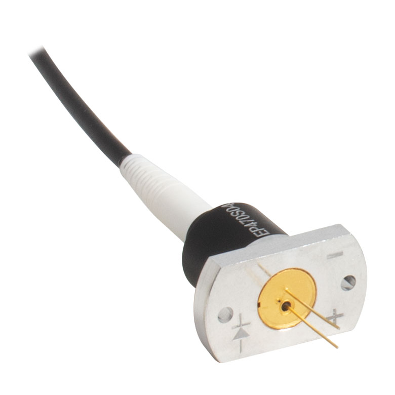
To connect the PCB to a driver, please note that the soldering pad labeled "+" is the Anode (+V), and the pad labeled "-" is the Cathode. These LEDs can be operated without connecting EEPROM IO and EEPROM GND, but both must be connected in order for the driver to read the current limit. The soldering pads on different items may be in different locations, but the labels are the same.
Collimation
These LEDs have large viewing angles, so for many applications it is beneficial to collimate the beam. See the Collimation tab for information on collimating the light from an LED.
Relative Power
The actual spectral output and total output power of any given LED will vary due to variations in the manufacturing process and operating parameters, such as temperature and current. Both a typical and minimum output power are specified to help you select

Click to Enlarge
Click Here for Data
The spectrum shown for M4300D1 and M5200D1 are ideal.
Please see their Spec Sheets for more information.

LED Lifetime and Long-Term Power Stability
One characteristic of LEDs is that they naturally exhibit power degradation with time. Often this power degradation is slow, but there are also instances where large, rapid drops in power, or even complete LED failure, occur. LED lifetimes are defined as the time it takes a specified percentage of a type of LED to fall below some power level. The parameters for the lifetime measurement can be written using the notation BXX/LYY, where XX is the percentage of that type of LED that will provide less than YY percent of the specified output power after the lifetime has elapsed. Thorlabs defines the lifetime of our LEDs as B50/L50, meaning that 50% of the LEDs with a given Item # will fall below 50% of the initial optical power at the end of the specified lifetime. For example, if a batch of 100 LEDs is rated for 150 mW of output power, 50 of these LEDs can be expected to produce an output power of ≤75 mW after the specified LED lifetime has elapsed.
Optimizing Thermal Management
In order to achieve stable optical output power and maximize lifetime from your LED, the MCPCB must be properly mounted to a heat sink using thermally conductive paste in order to minimize the degradation of optical output power caused by increased LED junction temperature (see the graph to the right).
To fully support the max optical power of the LED you intend to drive, ensure that the max voltage and max current of the driver are equal to or greater than those of the LED.
| Compatible Drivers | LEDD1B | UPLEDa | DC40a | DC2200a | DC4100a,b | DC4104a,b |
|---|---|---|---|---|---|---|
| Click Photos to Enlarge |  |
 |
 |
 |
 |
 |
| LED Driver Current Output (Max)c | 1.2 A | 1.2 A | 4.0 Ad | LED1 Terminal: 10.0 A LED2 Terminal: 2.0 Ae |
1.0 A per Channel | 1.0 A per Channel |
| LED Driver Forward Voltage (Max)f | 12 V | 8 V | 14.0 Vd | 50 V | 5 V | 5 V |
| Modulation Frequency Using External Input (Max) | 5 kHzg | - | 5 kHzg | 250 kHzg,h | 100 kHzg (Simultaneous Across all Channels) |
100 kHzg (Independently Controlled Channels) |
| External Control Interface(s) | Analog (BNC) | USB 2.0 | USB 2.0, TTL, and Analog (BNC) | USB 2.0 and Analog (BNC) | USB 2.0 and Analog (BNC) | USB 2.0 and Analog (8-Pin) |
| Main Driver Features | Very Compact Footprint 60 mm x 73 mm x 104 mm (W x H x D) |
USB-Controlled | Driver Current Up to 4.0 A, Manual and USB-Controlled |
Touchscreen Interface with Internal and External Options for Pulsed and Modulated LED Operation | 4 Channelsb | 4 Channelsb |
| EEPROM Compatible: Reads Out LED Data for LED Settings | - | |||||
| LCD Display | - | - | - |
Video Insight: Collimate Light from an LED
Collimating light from an LED or other large, incoherent source can be a surprisingly challenging task. The emitter’s size and the collimating lens’ focal length and numerical aperture (NA) all influence the characteristics of the collimated beam. It can also be hard to know when the lens is positioned optimally. In this video, two lenses with different NAs and focal lengths are used to demonstrate a couple of collimation approaches. In addition, the emerging image of the emitter and other typical features of beams provided by collimating lenses are explored.
| Item # | Information File | Available Ray Files | File Size | Click to Download |
|---|---|---|---|---|
| M385D1 | M385_Info.pdf | 1 Million Rays and 5 Million Rays | 147 MB | |
| M850D2a | SFH4715S_100413_info.pdf | 100,000 Rays, 500,000 Rays, and 5 Million Rays | 139 MB | |
| M940D2a | SFH_4725S_110413_info.pdf | 100,000 Rays, 500,000 Rays, and 5 Million Rays | 140 MB |
Ray data for Zemax is available for some of the bare LEDs incorporated into these high-powered light sources. This data is provided in a zipped folder that can be downloaded by clicking on the red document icons ( ) next to the part numbers in the pricing tables below. Every zipped folder contains an information file and one or more ray files for use with Zemax:
- Information File: This document contains a summary of the types of data files included in the zipped folder and some basic information about their use. It includes a table listing each document type and the corresponding filenames.
- Ray Files: These are binary files containing ray data for use with Zemax.
For the LEDs marked with an superscript "a" in the table to the right, the following additional pieces of information are also included in the zipped folder:
- Radiometric Color Spectrum: This .spc file is also intended for use with Zemax.
- CAD Files: A file indicating the geometry of the bare LED. For the dimensions of the high-power mounted LEDs that include the package, please see the support drawings provided by Thorlabs.
- Sample Zemax File: A sample file containing the recommended settings and placement of the ray files and bare LED CAD model when used with Zemax.
The table to the right summarizes the ray files available for each LED and any other supporting documentation provided.
| Posted Comments: | |
prathmesh ghag
(posted 2023-10-19 15:09:13.14) Sir,
Are these LED vacuum compatible.
Kindly tell for model M810D2
Thanks,
Prathmesh Ghag dpossin
(posted 2023-10-20 07:12:57.0) Dear Prathmesh,
Thank you for your feedback. Unfortunately none of our metal core PCB mounted LEDs are vacuum compatible. Su Bemo Heo
(posted 2023-06-22 17:18:01.56) Hi I just saw Specifications about [M167D4].
It' seems Nominal wavelength is 617nm but Peak Wavelength is 620 ~ 630nm so what's different between Nominal and Peak
Also what is Typical Wavelength(625nm) ? why is different Nominal Wavelength (617nm)
Thanks hkarpenko
(posted 2023-06-23 06:39:48.0) Dear customer,
thank you for your feedback. The nominal wavelength is the nominal wavelength at which the LED appears brightest to the human eye. The central wavelength spec is the measured wavelength from a spectrometer. This only makes a difference for some visible wavelengths. Since the emission wavelength and output power can vary due to the production process, we state a minimum, typical and maximum value, in between the peak wavelength will be located. This is based on our measurements and experience. wang xiaozhuo
(posted 2023-06-06 20:34:52.723) Hi thorlabs, I wonder do you have real rayfile of M780D2 LED for Lighttools? hchow
(posted 2023-06-07 10:20:14.0) Dear Mr. Wang, thank you for your feedback. I will reach out to you directly to address your issue. MARIO MARTINELLI
(posted 2023-02-24 13:28:12.4) What is the appropriate driver for M530D3? Thanks hchow
(posted 2023-02-24 09:20:03.0) Dear Mr. Martinelli, thank you for your feedback. Our LEDs on Metal-Core PCBs can be driven by our LEDD1B, DC2200, DC4100, and DC4104 (the latter two require the DC4100-Hub). You can additionally purchase the CAB-LEDD1, LED connect cable to connect the LED to the LED driver. ke chen
(posted 2022-07-14 04:22:02.07) 我想用一段二进制伪随机编码对光源的亮灭进行调制,从而间歇性的使石墨烯产生光电效应而产生离子,请问这个产品能完成这个任务吗 mdiekmann
(posted 2022-07-18 06:05:04.0) Thank you for contacting us. A member of our Chinese-speaking tech support team will reach out to you directly to assist. Mehrdad Hosseini
(posted 2022-06-13 08:51:04.24) Hello,
As you mentioned in the datasheet, the maximum current for M595D3 is 1500 mA, but I can't apply more than 800 mA with 3.2V. Can I increase the voltage to reach maximum current (and highest intensity)? If so, to what extent?
Best Regards,
Mehrdad fmortaheb
(posted 2022-06-14 03:14:41.0) Dear Mehrdad, Thank you very much for your inquiry. we have contacted you directly to provide further assistance and troubleshooting. Faye Clever
(posted 2021-12-01 08:44:07.61) I have been using these MINTD3 LEDs for an optogenetics project I am working on with model organism C. elegans for a little over a year. The LEDs have been exactly what I needed. My only concern is the ease of soldering these LEDs. I have had a number of people work on the soldering with some frustration. Because it has been multiple people, all of whom have respectable soldering experience, I am inclined to believe that there may be some issue with the LEDs themselves. I have so far purchased 9 MINTD3s and the soldering has actually detached from the LEDs during use - when I first set up the LEDs, everything works fine, but when I come back hours later the soldering will be detached. I could be wrong, but if this is in fact an issue with the LEDs' soldering then I figured you would want to know. dpossin
(posted 2021-12-06 05:04:52.0) Dear Faye,
Thank you for your feedback. I reach out to you directly in order to discuss this. Hyeonsoo OH
(posted 2021-10-01 17:05:30.257) Hello.
I`m a assistant manager in Company called U2medtek which is medical engineering in korea.
We bought it. and we are very satisfied about it.
Do you have Certificate of EN-62471 for it?
If you have please send PDF file on e-mail.
For making medical equipment, We need that certs.
If you want to know about us, you can send a e-mail to this address.
and this is our homepage address.
Homepage: www.U2medtek.com
thank you
Best Regards soswald
(posted 2021-10-04 05:52:55.0) Dear Hyeonsoo OH,
thank you for your feedback. I am glad to hear you are satisfied with the M780D2.
We have rated this LED as RG0 according to EN-62471, as stated in the specification sheet: https://www.thorlabs.de/drawings/86f2f178eb4c904c-E3DE4C1C-0EB5-F577-6725F18F3430EA4E/M780D2-SpecSheet.pdf
I have reached out to you directly in order to provide further assistance if needed. Hajun Song
(posted 2020-11-09 01:45:59.967) I want to use the LD as a flash for the high speed flash. So, the LD should be modulated as fast as possible. Could you give me a information about the LD's bandwidth or rising time? dpossin
(posted 2020-11-09 10:13:11.0) Dear Hajun,
Thank you for your feedback. Unfortunately we do not have information on the rise time of our metalcore PCB LEDs due to the fact that we are bandwidth limited by our drivers. However a good assumption is a rise time of at least 100ns which corresponds to an 3dB bandwidth of 3.5 MHz. Ulrich Leischner
(posted 2020-07-09 05:32:47.76) Hallo
gäbe es diese LED auch für 1000mA Stromstärke?
wir benützen den Wellenlängenbereich ab 1070nm für quasi-IR Imaging, also den Grenzbereich der grad noch mit Silizium-Chips machbar ist. Mit einer IR-Quelle und einem 1070nm Langpassfilter hat man ganz gute ergebnisse. Unsere Stromversorgungen sind standardisiert auf 1000mA. Wenn es da LEDs gäbe im Bereich 1050nm-1200nm mit 1000mA wären die für uns gut zu gebrauchen. Gäbe es da inzwischen LEDs in diesem Bereich?
Grüße
Ulrich Leischner MKiess
(posted 2020-07-10 09:36:13.0) Vielen Dank für Ihre Anfrage. Eine IR-LED, mit einer Wellenlänge zwischen 1050nm und 1200nm, auf einem Metallkern PCB, welche bei 1000mA betrieben werden kann, haben wir leider nicht als standard Produkt in unserem Sotrtiment. Eine Übersicht aller LEDs können Sie unter folgendem Link finden:
https://www.thorlabs.de/newgrouppage9.cfm?objectgroup_ID=6071&tabname= LED Selection Guide
Ich habe Sie direkt kontaktiert um die genauen Anforderungen mit Ihnen zu diskutieren. alekkom
(posted 2017-12-15 11:09:23.127) Can I use laser diode driver LD3000R as LED driver for M780D3 diode? swick
(posted 2017-12-20 03:52:04.0) This is a response from Sebastian at Thorlabs. Thank you for the inquiry.
In general it should work to drive LEDs with constant current drivers so LD3000R (2.5 A , 12 V) should be compatible to M780D3 (800 mA, 7.8 V). ludoangot
(posted 2017-11-16 22:57:56.71) Which of your white LED has the highest Color Rendition Index (CRI)? mvonsivers
(posted 2017-11-21 04:47:52.0) This is a response from Moritz at Thorlabs. Thank you for you inquiry.
Unfortunately, we cannot specify CRI values for our LEDs.
I will contact you directly for further information. ludoangot
(posted 2016-05-24 23:39:01.57) Do you offer sm1 sized blank mounting plates for these LED? I have in mind 2 configurations: a 1" pre-drilled plate to insert in sm1 tubes or the same but with SM1 external thread. shallwig
(posted 2016-05-25 02:29:13.0) This is a response from Stefan at Thorlabs. Thank you very much for your inquiry. These LEDs on Metal-Core PCB must still be mounted onto an appropriate heat sink using thermal paste to ensure proper operation and to maximize operating lifetime. We do not offer these heat sinks separately. Our mounted LEDs with heatsink http://www.thorlabs.com/newgrouppage9.cfm?objectgroup_ID=2692 feature an internal SM1 Threading for attaching collimation adapters or 1’’ lens tubes.
I will contact you directly to discuss your application in more detail. kwestla
(posted 2015-01-29 13:03:14.38) What is the control voltage needed to turn the device on via the EEPROM IO, is it TTL, CMOS etc? shallwig
(posted 2015-01-30 05:24:28.0) This is a response from Stefan at Thorlabs. Thank you very much for your inquiry. The EPROM cannot be used to turn the LED on. This chip only has saved information about the maximum driving current for this specific LED. It gets connected with an EPROM compatible driver like the DC2100 via the IO and GND Pad but the LED and EPROM have two different circuits. The driver reads out the EPROM information and sets the current limit accordingly.
The M385D1 needs to be supplied via Cathode and Anode Pad with a constant current of 700 mA, the current must not exceed the max current of 700 mA. The current source must be able to deliver this current at a “Forward Voltage” of 4.3 V.
I will contact you directly to discuss your application in detail. jamesfreal
(posted 2013-08-27 11:58:01.013) The Excel data file for the M365D1 is not correct on your web site. It looks like it contains the spectral data for the M505D2. Could you send me the correct file?
Thanks
James Freal sharrell
(posted 2013-08-27 12:35:00.0) Response from Sean at Thorlabs: Thank you for contacting us. We’ve updated the file linked on our website with the correct data. |
This tab includes all LEDs sold by Thorlabs. Click on More [+] to view all available wavelengths for each type of LED pictured below.
| Light Emitting Diode (LED) Selection Guide | ||||||
|---|---|---|---|---|---|---|
| Click Photo to Enlarge (Representative; Not to Scale) |
 |
 |
 |
 |
 |
 |
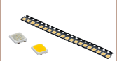
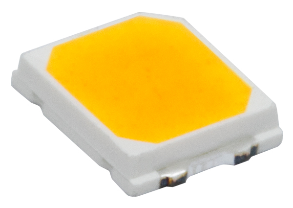
| Type | Unmounted LEDs | Pigtailed LEDs | LEDs in SMT Packages |
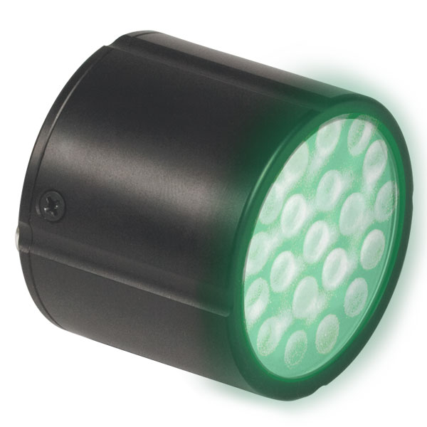
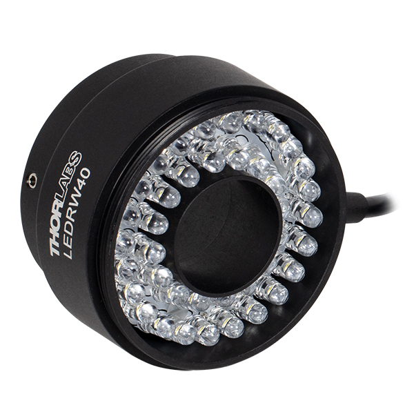
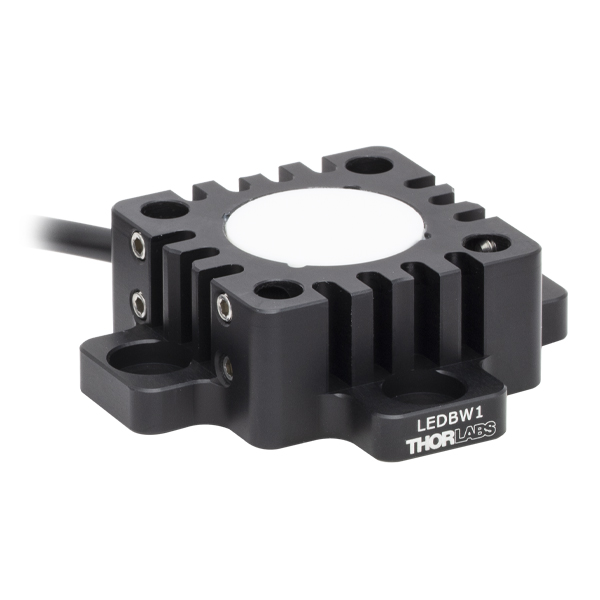
LED Arrays | LED Ring Light | Cage-Compatible Diffuse Backlight LED |
| Light Emitting Diode (LED) Selection Guide | ||||||
|---|---|---|---|---|---|---|
| Click Photo to Enlarge (Representative; Not to Scale) |
 |
 |
 |
 |
 |
 |
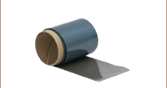
| Type | PCB- Mounted LEDs |
Heatsink- Mounted LEDs |
Collimated LEDs for Microscopyb | Fiber- Coupled LEDsc |
High-Power LEDs for Microscopy | Multi-Wavelength LED Source Optionsd |
Please note that our deep UV LEDs radiate intense UV light during operation. Precautions must be taken to prevent looking directly at the UV light, and UV light protective glasses must be worn to avoid eye damage. Exposure of the skin and other body parts to UV light should be avoided.
| Item # | Infoa,b | Nominal Wavelengthb |
LED Output Power | Bandwidth (FWHM) |
Irradiancec | Maximum Current (CW) |
Forward Voltage |
Viewing Angle (Full Angle at Half Max) |
Emitter Size | MCPCB Thickness |
|
|---|---|---|---|---|---|---|---|---|---|---|---|
| Minimum | Typical | ||||||||||
| M265D4 | 265 nm | 38.4 mW | 55.7 mW | 11 nm | 0.5 µW/mm2 | 440 mA | 6.9 V | 120º | 1 mm x 0.75 mm | 1.6 mm | |
| M275D2 | 275 nm | 45 mW | 80 mW | 11 nm | 0.8 µW/mm2 | 700 mA | 7.3 V | 118° | 2 mm x 2 mm | 1.6 mm | |
| M275D3 | 275 nm | 47.3 mW | 68.3 mW | 10 nm | 0.5 µW/mm2 | 300 mA | 12 V | 120° | 2.7 mm x 3.3 mm | 1.6 mm | |
| M280D4 | 280 nm | 78 mW | 114 mW | 10 nm | 1 µW/mm2 | 500 mA | 6.26 V | 114°d | 1 mm x 1 mm | 1.6 mm | |
| M300D3 | 300 nm | 26 mW | 32 mW | 20 nm | 0.3 µW/mm2 | 350 mA | 8.0 V (Max) | 130° | 1 mm x 1 mm | 1.6 mm | |
| M310D1 | 310 nm | 38.5 mW | 56.5 mW | 30 nm | 0.76 µW/mm2 | 600 mA | 5 V | 120°d | 1 mm x 1 mm | 1.6 mm | |
| M325D3 | 325 nm | 25 mW | 35 mW | 12 nm | 0.44 µW/mm2 (Max) | 600 mA | 5.2 V | 120° | 1 mm x 1 mm | 1.6 mm | |
| M340D4 | 340 nm | 45.5 mW | 69.2 mW | 10 nm | 0.6 µW/mm2 | 600 mA | 6.6 V | 120°d | 1 mm x 1 mm | 2.4 mm | |
Please note that our UV LEDs radiate intense UV light during operation. Precautions must be taken to prevent looking directly at the UV light, and UV light protective glasses must be worn to avoid eye damage. Exposure of the skin and other body parts to UV light should be avoided.
| Item # | Infoa,b | Nominal Wavelengthb |
LED Output Power | Bandwidth (FWHM) |
Irradiance (Typical)c |
Maximum Current (CW) |
Forward Voltage |
Viewing Angle (Full Angle at Half Max) |
Emitter Size | MCPCB Thickness |
|
|---|---|---|---|---|---|---|---|---|---|---|---|
| Minimum | Typical | ||||||||||
| M365D2 | 365 nm | 1150 mWd | 1400 mWd | 9 nm | 17.6 µW/mm2 d | 1700 mA | 4.0 V | 120° | 1.4 mm x 1.4 mm | 2.4 mm | |
| M375D4 | 375 nm | 1270 mW | 1540 mW | 9 nm | 19.2 µW/mm2 | 1400 mA | 3.6 V | 130° | 1 mm x 1 mm | 2.4 mm | |
| M385D2 | 385 nm | 1650 mW | 1830 mW | 12 nm | 23.3 µW/mm2 | 1700 mA | 3.9 V | 120° | 1.4 mm x 1.4 mm | 2.4 mm | |
| M395D3 | 395 nm | 400 mW | 535 mW | 16 nm | 6.7 µW/mm2 | 500 mA | 4.5 V | 126° | 1 mm x 1 mm | 2.4 mm | |
| M395D4 | 395 nm | 1420 mW | 2050 mW | 11 nm | 22.8 µW/mm2 | 1400 mA | 4.0 V | 120° | 2.5 mm x 2.5 mm | 2.4 mm | |
| M405D2 | 405 nm | 1500 mW | 1700 mW | 12 nm | 24.6 µW/mm2 | 1400 mA | 3.45 V | 120° | 1.4 mm x 1.4 mm | 2.5 mm | |
Please note that the 415 nm (violet), 430 nm (violet), and 450 nm (royal blue) LEDs radiate intense UV light during operation. Precautions must be taken to prevent looking directly at the UV light, and UV light protective glasses must be worn to avoid eye damage. Exposure of the skin and other body parts to the UV light should be avoided.
| Item # | Infoa,b | Nominal Wavelengthb,c |
LED Output Power | Bandwidth (FWHM) |
Irradiance (Typical)d |
Maximum Current (CW) |
Forward Voltage |
Viewing Angle (Full Angle at Half Max) |
Emitter Size | MCPCB Thickness |
|
|---|---|---|---|---|---|---|---|---|---|---|---|
| Minimum | Typical | ||||||||||
| M415D2 | 415 nm | 1640 mW | 1940 mW | 14 nm | 19.5 µW/mm2 | 2000 mA | 3.15 V | 138° | 1.4 mm x 1.4 mm | 2.4 mm | |
| M430D3 | 430 nm | 529.2 mW | 757.6 mW | 17 nm | 25.7 µW/mm2 | 500 mA | 3.66 V | 126° e | 1 mm x 1 mm | 2.4 mm | |
| M450D4 | 450 nm | 2118.1 mW | 3041.5 mW | 18 nm | 34.2 µW/mm2 | 2000 mA | 3.2 V | 120° f | 1.5 mm x 1.5 mm | 2.4 mm | |
| M455D3 | 455 nm | 1150 mW | 1445 mW | 18 nm | 32 µW/mm2 | 1000 mA | 3.25 V | 80° | 1 mm x 1 mm | 1.6 mm | |
| M470D4 | 470 nm | 809 mW | 1161.7 mW | 28 nm | 21.4 µW/mm2 | 1000 mA | 3.8 V | 80° | 1 mm x 1 mm | 1.6 mm | |
| M490D3 | 490 nm | 205 mW | 240 mW | 26 nm | 2.5 µW/mm2 | 350 mA | 3.8 V (Max) | 128° | 1 mm x 1 mm | 2.4 mm | |
| M505D4 | 508 nm | 550 mW | 810 mW | 29 nm | 9.0 µW/mm2 | 1200 mA | 3.4 V | 120° | 1 mm x 1 mm | 1.6 mm | |
| M530D3 | 530 nm | 370 mW | 480 mW | 35 nm | 9.46 µW/mm2 | 1000 mA | 3.6 V | 80° | 1 mm x 1 mm | 1.6 mm | |
| MINTD3 | 554 nm | 650 mW | 815 mW | - | 12.4 µW/mm2 | 1225 mA | 3.5 V | 120° | 1 mm x 1 mm | 2.4 mm | |
| M565D2g | 565 nm | 880 mW | 979 mW | 104 nm | 11.7 µW/mm2 | 1000 mA | 3.1 V (Max) | 125° | 1 mm x 1 mm | 1.6 mm | |
| Item # | Infoa,b | Nominal Wavelengthb,c |
LED Output Power | Bandwidth (FWHM) |
Irradiance (Typical)d |
Maximum Current (CW) |
Forward Voltage |
Viewing Angle (Full Angle at Half Max) |
Emitter Size | MCPCB Thickness |
|
|---|---|---|---|---|---|---|---|---|---|---|---|
| Minimum | Typical | ||||||||||
| M590D3 | 590 nm | 230 mW | 300 mW | 15 nm | 6.0 µW/mm2 | 1000 mA | 2.5 V | 80° | 1 mm x 1 mm | 1.6 mm | |
| M595D3e | 595 nm | 820 mW | 1217 mW | 64 nm | 13.5 µW/mm2 | 1500 mA | 3.0 V | 120° | 2.9 mm x 2.9 mm | 2.4 mm | |
| M617D4 | 617 nm | 737.4 mW | 1006.2 mW | 16 nm | 19.4 µW/mm2 | 1000 mA | 2.9 V | 80°f | 1 mm x 1 mm | 1.6 mm | |
| M625D3 | 625 nm | 700 mW | 920 mW | 17 nm | 21.9 µW/mm2 | 1000 mA | 2.5 V | 80° | 1 mm x 1 mm | 1.6 mm | |
| M660D2 | 660 nm | 940 mW | 1050 mW | 20 nm | 20.9 µW/mm2 | 1200 mA | 2.6 V | 100° | 1.5 mm x 1.5 mm | 1.6 mm | |
| M680D2 | 680 nm | 180 mW | 210 mW | 22 nm | 14.5 µW/mm2 | 600 mA | 2.5 V | 18° | 1 mm x 1 mm | 2.4 mm | |
| M700D2 | 700 nm | 80 mW | 125 mW | 20 nm | 1.0 µW/mm2 | 500 mA | 2.7 V | 128° | 1 mm x 1 mm | 2.4 mm | |
| M730D4 | 727 nm | 780 mW | 1130 mW | 38 nm | 13.8 µW/mm2 | 1000 mA | 2.5 V | 120° | 1 mm x 1 mm | 1.6 mm | |
| Item # | Infoa,b | Nominal Wavelengthb |
LED Output Power | Bandwidth (FWHM) |
Irradiance (Typical)c |
Maximum Current (CW) |
Forward Voltage |
Viewing Angle (Full Angle at Half Max) |
Emitter Size | MCPCB Thickness |
|
|---|---|---|---|---|---|---|---|---|---|---|---|
| Minimum | Typical | ||||||||||
| M780D2 | 780 nm | 200 mW | 300 mW | 28 nm | 47.3 µW/mm2 | 800 mA | 2.0 V | 20° | 1 mm x 1 mm | 2.4 mm | |
| M780D3 | 780 nm | 800 mW | 950 mW | 30 nm | 13.3 µW/mm2 | 800 mA | 7.8 V | 120° | Ø3 mm (3 Emitters) |
1.6 mm | |
| M810D4 | 810 nm | 810 mW | 1190 mW | 30 nm | 15.9 µW/mm2 | 1000 mA | 3.6 V | 128° | 1 mm x 1 mm | 2.4 mm | |
| M850D2 | 850 nm | 900 mW | 1100 mW | 30 nm | 22.9 µW/mm2 | 1200 mA | 2.95 V | 90° | 1 mm x 1 mm | 1.6 mm | |
| M850D3 | 850 nm | 1400 mW | 1600 mW | 30 nm | 19.4 µW/mm2 | 1500 mA | 3.85 V (Max) | 150° | 1 mm x 1 mm | 1.6 mm | |
| M880D2 | 880 nm | 300 mW | 350 mW | 50 nm | 5.6 µW/mm2 | 1000 mA | 1.7 V | 132° | 1 mm x 1 mm | 2.4 mm | |
| M940D2 | 940 nm | 800 mW | 1000 mW | 37 nm | 19.1 µW/mm2 | 1000 mA | 2.75 V | 90° | 1 mm x 1 mm | 1.6 mm | |
| M970D3 | 970 nm | 600 mW | 720 mW | 60 nm | 7.4 µW/mm2 | 1000 mA | 1.9 V | 130° | 1 mm x 1 mm | 2.4 mm | |
| M1050D1 | 1050 nm | 50 mW | 70 mW | 60 nm | 1.9 µW/mm2 | 700 mA | 1.5 V | 120° | 1 mm x 1 mm | 2.4 mm | |
| M1050D3 | 1050 nm | 160 mW | 210 mW | 37 nm | 3.7 µW/mm2 | 600 mA | 1.6 V (Max) | 128° | 1 mm x 1 mm | 2.4 mm | |
| M1100D1 | 1100 nm | 168 mW | 252 mW | 50 nm | 18.1 µW/mm2 | 1000 mA | 1.4 V | 18° | 1 mm x 1 mm | 2.4 mm | |
| M1200D3 | 1200 nm | 136 mW | 200 mW | 65 nm | 2.6 µW/mm2 | 1000 mA | 2.2 V | 130° | 1 mm x 1 mm | 2.4 mm | |
| M1300D2 | 1300 nm | 25 mW | 30 mW | 80 nm | 0.6 µW/mm2 | 500 mA | 1.4 V | 134° | 1 mm x 1 mm | 2.4 mm | |
| M1300D3 | 1300 nm | 122.8 mW | 182.1 mW | 80 nm | 1.6 µW/mm2 | 1000 mA | 1.7 V | 130° | 1 mm x 1 mm | 2.4 mm | |
| M1450D3 | 1450 nm | 81.8 mW | 120.7 mW | 95 nm | 1.5 µW/mm2 | 700 mA | 1.88 V | 130° | 1 mm x 1 mm | 2.4 mm | |
| M1550D3 | 1550 nm | 46 mW | 70 mW | 120 nm | 1.1 µW/mm2 | 1000 mA | 1.3 V | 128°d | 1 mm x 1 mm | 2.4 mm | |
| M1650D2 | 1650 nm | 13 mW | 16 mW | 120 nm | 1.2 µW/mm2 | 600 mA | 1.1 V | 20° | 1 mm x 1 mm | 2.4 mm | |
| M1900D1 | 1900 nm | 10 mW | 15 mW | 120 nm | 2.2 µW/mm2 | 1000 mA | 1.2 V | 18° | 1 mm x 1 mm | 2.4 mm | |
| Item # | Infoa,b | Nominal Wavelengthb |
LED Output Power | Bandwidth (FWHM) |
Maximum Current (CW) |
Forward Voltage |
Viewing Angle (Full Angle at Half Max) |
Emitter Size | MCPCB Thickness |
|
|---|---|---|---|---|---|---|---|---|---|---|
| Minimum | Typical | |||||||||
| M3400D1 | 3400 nm | 2.2 mW | 3.3 mW | 800 nm | 200 mA | 4.1 V | 130° | 0.8 mm x 1 mm | 1.6 mm | |
| M4300D1 | 4300 nm | 1.1 mW | 1.67 mW | 800 nm | 200 mA | 3.9 V | 130° | 0.8 mm x 1 mm | 1.6 mm | |
| M5200D1 | 5200 nm | 0.8 mW | 1.3 mW | 800 nm | 200 mA | 4 V | 130° | 0.8 mm x 1 mm | 1.6 mm | |
Our dual-peak LED was designed for applications requiring illumination in both red and blue portions of the spectrum, such as horticulture. This purple LED features dual peaks at 455 nm and 640 nm, respectively, to stimulate photosynthesis (see graph to compare the absorption peaks of photosynthesis pigments with the LED spectrum). The LED was designed to maintain the red/blue ratio of the emission spectrum over its lifetime to provide high uniformity of plant growth.
| Item # | Infoa,b | Nominal Wavelengthb |
LED Output Power | Bandwidth (FWHM) |
Irradiance (Typical)c |
Maximum Current (CW) |
Forward Voltage |
Viewing Angle (Full Angle at Half Max) |
Emitter Size | MCPCB Thickness |
|
|---|---|---|---|---|---|---|---|---|---|---|---|
| Minimum | Typical | ||||||||||
| MPRP1D2d | 455 nm (12.5%e) / 640 nm |
275 mW | 325 mW | N/A | 3.7 µW/mm2 | 300 mA | 3.1 V | 115° | 1 mm x 2 mm | 1.6 mm | |
Our warm, neutral, and cold white LEDs feature broad spectra that span several hundred nanometers. The difference in appearance among these LEDs can be described using the correlated color temperature, which indicates that the LEDs color appearance is similar to a black body radiator at that temperature. In general, warm white LEDs offer a spectrum similar to a tungsten source, while cold white LEDs have a stronger blue component to the spectrum; neutral white LEDs provide a more even illumination spectrum over the visible range than warm white or cold white LEDs. Cold white LEDs are more suited for fluorescence microscopy applications or cameras with white balancing, because of a higher intensity at most wavelengths compared to warm white LEDs. Neutral white LEDs are ideal for horticultural applications.
| Item # | Infoa,b | Correlated Color Temperatureb |
LED Output Power | Bandwidth (FWHM) |
Irradiance (Typical)c |
Maximum Current (CW) |
Forward Voltage |
Viewing Angle (Full Angle at Half Max) |
Emitter Size | MCPCB Thickness |
|
|---|---|---|---|---|---|---|---|---|---|---|---|
| Minimum | Typical | ||||||||||
| MWWHD4d | 3000 K | 1713 mW | 2499 mW | N/A | 27.2 µW/mm2 | 700 mA | 12.1 V | 135° | Ø3.6 mm | 1.6 mm | |
| MWUVD1d | 4000 Ke | 235 mW | 338 mW | N/A | 4.0 µW/mm2 | 125 mA | 6.3 V | 120°f | 2 mm x 1 mm | 1.6 mm | |
| MNWHD3d | 4000 K | 1400 mWg | 2040 mWg | N/A | 25 µW/mm2 g | 2500 mA | 3.1 Vg | 120°h | Ø1.58 mm | 2.4 mm | |
| MNWHD2d | 4900 K | 740 mW | 880 mW | N/A | 7.7 µW/mm2 | 1225 mA | 2.9 V | 150° | 1 mm x 1 mm | 2.4 mm | |
| MCWHD5d | 6500 K | 930 mW | 1370 mW | N/A | 25.9 µW/mm2 | 1300 mA | 3.3 V | 80° | 1 mm x 1 mm | 1.6 mm | |
| MCWHD6d | 6500 K | 942 mW | 1353 mW | N/A | 11.8 µW/mm2 | 1300 mA | 4.51 V | 150° | 1 mm x 1 mm | 1.6 mm | |
| MCWHD8d | 6500 K | 1300.9 mW | 1882.0 mW | N/A | 22.5 µW/mm2 | 2000 mA | 3.6 V | 125° | Ø3 mm | 1.6 mm | |
| MCWHD7d | 6500 K | 2064.8 mW | 2998.0 mW | N/A | 33.3 µW/mm2 | 700 mA | 12.9 V | 135° | Ø3.7 mm | 1.6 mm | |
The MBB1D1 broadband LED has a relatively flat spectral emission over a wide wavelength range. Its 10 dB bandwidth ranges between 470 nm and 850 nm. The MBB2D1 broadband LED features a spectrum with peaks at approximately 770 nm, 860 nm, and 940 nm.
| Item # | Infoa,b | Wavelengthb | LED Output Power | Bandwidth (FWHM) |
Irradiance (Typical)c |
Maximum Current (CW) |
Forward Voltage |
Viewing Angle (Full Angle at Half Max) |
Emitter Size | MCPCB Thickness |
|
|---|---|---|---|---|---|---|---|---|---|---|---|
| Minimum | Typical | ||||||||||
| MBB1D1d | 470 - 850 nm (10 dB Bandwidth) |
70 mW | 80 mW | 280 nm | 0.9 µW/mm2 | 500 mA | 3.6 V | 120° | 1 mm x 1 mm | 2.4 mm | |
| MBB2D1 | 770 nm, 860 nm & 940 nm (Peak Wavelengths) |
740 mW | 1090 mW | N/A | 13.5 µW/mm2 | 1000 mA | 4.8 V | 120° | 1 mm x 1 mm | 1.6 mm | |

 Zoom
Zoom
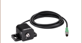
 Male M8x1 Connector |
Pin | Description | Wire Color |
|---|---|---|---|
| 1 | LED Anode | Brown | |
| 2 | LED Cathode | White | |
| 3 | EEPROM GND | Black | |
| 4 | EEPROM IO | Blue |
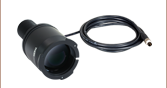
- 4-Pin M8 Connector on One Side
- 4 Bare Wires on Other Side
- 2 m Long, 24 AWG Wires
The 4-Pin M8 connection cable can be used to connect the LEDs on metal-core PCBs to the following Thorlabs LED drivers: LEDD1B, DC40, DC2200, DC4100, and DC4104 (the latter two require the DC4100-HUB).
Pin Connections
The diagram above shows the male connector for use with the above Thorlabs LED drivers. The connector is a standard M8x1 sensor circular connector. Pins 1 and 2 are the connection to the LED. Please note that the bare PCB board LEDs shown on this page do not include an EEPROM like our mounted LEDs; hence pins 3 and 4 should not be connected. Also, note that the pin connection diagram shown here may not be valid for third-party LED drivers.
For customers using their own power supplies, we also offer a female 4-pin M8 connector cable (item # CON8ML-4).