Aspheric Condenser Lenses with Diffuser Surface
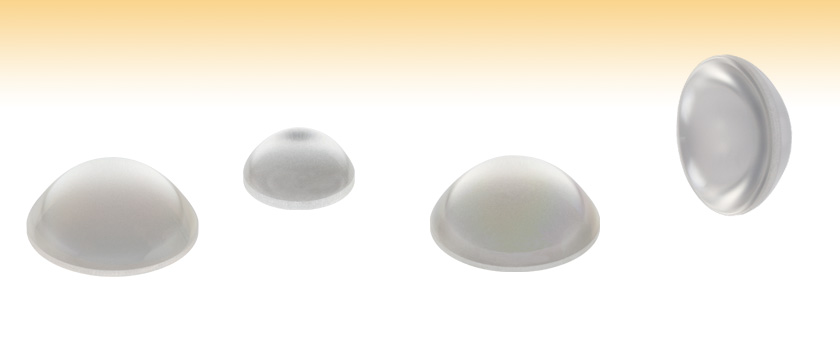
- Combines Aspheric Condenser with Diffuser on the Plano Side of the Lens
- 600 Grit and 1500 Grit Versions Available
- Uncoated or AR Coated for 350 - 700 nm or 650 - 1050 nm
- Lenses with NA of 0.60
ACL5040U-DG15-A
(Ø50 mm)
ACL2520U-DG15
(Ø25 mm)
ACL5040U-DG6-B
(Ø50 mm)
Plano Surface of ACL5040U-DG15

Please Wait
| General Specifications | |
|---|---|
| Substrate | B270 Optical Crown Glass |
| Wavelength Range | Uncoated: 380 - 2100 nm A: 350 - 700 nm B: 650 - 1050 nm |
| Reflectance Over AR Coating Range for Coated Optics (Avg., AOI = 0°) |
Ravg < 0.5% |
| Focal Length Tolerance | ±8% |
| Design Wavelength | Visible |
| Surface Quality (Asphere Side) | 80-50 Scratch-Dig |
| Uncoated Transmission Graph (Click Here to Download Raw Data) |
|
| A Coating Reflectance Graph (Click Here to Download Raw Data) |
|
| B Coating Reflectance Graph (Click Here to Download Raw Data) |
|
| Diameter Tolerance | +0.0 mm / -0.5 mm |
| Center Thickness Tolerance | ±0.3 mm |
| Centration | <30 arcmin |
| Temperature (Max) | 250 °C (482 °F) |
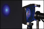
Click to Enlarge
Light from an LED Collimated by a Non-Diffusing Condenser Lens
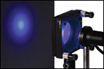
Click to Enlarge
Light from an LED Collimated by a Condenser Lens with a Diffuser Surface
Features
- Combines a Condenser and a Diffuser into a Single, Compact Optic
- 25 mm and 50 mm Diameters Available
- 600 or 1500 Grit Polished Versions Available
- 20 mm or 40 mm Focal Length Versions Available
- Available Uncoated or AR-Coated for 350 - 700 nm or 650 - 1050 nm on Aspheric Surface
- Offers Higher NA and Larger Aperture than Spherical Lenses
Thorlabs' Aspheric Condenser Lenses with Diffusers are designed for collimating light from lamps, LEDs, or similar sources into a highly uniform illumination pattern. We offer two sizes (Ø25 mm and Ø50 mm) to accommodate varying application needs. These lenses are available in either 600 grit or 1500 grit polished versions. A finer grit (e.g. 1500) has a small diffusion pattern, while a coarser grit (e.g. 120) will have a larger diffuser pattern. These aspheric condenser lenses are available uncoated for use in the 380 - 2100 nm range or with an AR coating for the 350 to 700 nm (-A Coating) or 650 to 1050 nm (-B Coating) range. For reflectance plots, please see the table to the right.
When collimating high-power LEDs with a standard lens, the structure of the source can ultimately be imaged through the lens, resulting in a highly non-uniform illumination pattern (see the top image on the right). For many applications, this is not desired. Adding a diffuser on the plano surface ensures a uniform illumination of the light source in the far field (see the bottom image on the right).
The aspheric surface is precision molded on the aspheric side and polished with 600 or 1500 grit on the plano side. Polished diffusers are advantageous over sand blasted diffusers as their surfaces have greater uniformity.
Thorlabs offers many types of mounting solutions for these lenses. Extra-thick retaining rings are available with SM1 (1.035"-40) and SM2 (2.035"-40) threading that provide extra clearance for spanner wrenches when mounting these lenses (see the Lens Mounting Guide tab for more information). Please visit our Fixed Optic Mounts Guide and Mirror Mounts Guide for possible mouting options available.
Aspheric Lens Design Equation

| Item # Prefixa | ACL2520U | ACL5040U |
|---|---|---|
| R (mm) | 10.462 | 20.923 |
| k | -0.6265 | -0.6405 |
| A2 | 0 | 0 |
| A4 | 1.5E-5 | 2.0E-6 |
| A6 | 0 | 0 |
| A8 | 0 | 0 |
| A10 | 0 | 0 |
| A12 | 0 | 0 |
| S2b Radius (mm) |
Plano | Plano |
Thorlabs' retaining rings are used to secure unmounted optics within lens tubes or optic mounts. These rings are secured in position using a compatible spanner wrench. For flat or low-curvature optics, standard retaining rings manufactured from anodized aluminum are available from Ø5 mm to Ø4". For high-curvature optics, extra-thick retaining rings are available in Ø1/2", Ø1", and Ø2" sizes.
Extra-thick retaining rings offer several features that aid in mounting high-curvature optics such as aspheric lenses, short-focal-length plano-convex lenses, and condenser lenses. As seen in the animation to the right, the guide flange of the spanner wrench will collide with the surface of high-curvature lenses when using a standard retaining ring, potentially scratching the optic. This contact also creates a gap between the spanner wrench and retaining ring, preventing the ring from tightening correctly. Extra-thick retaining rings provide the necessary clearance for the spanner wrench to secure the lens without coming into contact with the optic surface.
| Posted Comments: | |
Josh Philipson
(posted 2022-02-23 08:38:56.3) Hi, Is there a Zemax file for ACL2520U-DG6 please? Thank you, Josh ksosnowski
(posted 2022-02-25 06:55:57.0) Thanks for contacting Thorlabs. Unfortunately we do not have Zemax files for these lenses with diffusers attached, however we do have files for the base lens like ACL2520U-A. john.w.easton
(posted 2018-12-13 12:44:38.303) Is the transmission curve shown for the 600 grit or 1500 grit diffuser? I am particularly interested in the transmission of 1500 grit at 725 nm (the ACL2520 lens specifically)
Thanks! mmcclure
(posted 2019-04-01 03:47:45.0) Hello, thank you for contacting us. The transmission curve shown is for the 10 mm thick B270 substrate. These parts transmit well at 725 nm, but note the throughput will depend on the collection method you are using. tcohen
(posted 2013-01-03 12:16:00.0) Response from Tim at Thorlabs to Stephan: We do not have Zemax models for these currently. We will take an empirical scan and model the surface to simulate the diffuser scatter onto the ACL2520 Zemax models. shenze
(posted 2012-12-18 15:19:37.357) Hello, can you provide ZEMAX or TracePro data for ACL2520-DG6-A and ACL2520-DG15-A? Thank you in advance. Stephan tcohen
(posted 2012-03-02 18:06:00.0) Response from Tim at Thorlabs to paul.lauria: Thank you for contacting us. I have sent you the data directly. paul.lauria
(posted 2012-03-01 14:42:08.0) Hi, is there a Zemax file for a ACL2520-DG6-A? Thank you. |

| Item # Prefixa | Diameter (mm) |
Focal Length (mm)b |
Focal Shift (Raw Data) |
f/#c | Clear Aperture (mm) |
Back Focal Length (mm) |
Numerical Aperture (NA)d |
Center Thickness (mm) |
Edge Thickness (mm) |
Non-Aspheric Surface |
Suggested Lens Mounts |
Reference Drawing |
|---|---|---|---|---|---|---|---|---|---|---|---|---|
| ACL2520U-DG6 | 25.0 | 20.1 | 0.89 | >22.5 | 12 | 0.60 | 12.0 | 2.8 | Plano | LH1(/M) | ||
| ACL5040U-DG6 | 50.0 | 40.0 | 0.89 | >45.0 | 26 | 0.60 | 21.0 | 2.6 | Plano | LH2(/M) |

| Item # Prefixa | Diameter (mm) |
Focal Length (mm)b |
Focal Shift (Raw Data) |
f/#c | Clear Aperture (mm) |
Back Focal Length (mm) |
Numerical Aperture (NA)d |
Center Thickness (mm) |
Edge Thickness (mm) |
Non-Aspheric Surface |
Suggested Lens Mounts |
Reference Drawing |
|---|---|---|---|---|---|---|---|---|---|---|---|---|
| ACL2520U-DG15 | 25.0 | 20.1 | 0.89 | >22.5 | 12 | 0.60 | 12.0 | 2.8 | Plano | LH1(/M) | ||
| ACL5040U-DG15 | 50.0 | 40.0 | 0.89 | >45.0 | 26 | 0.60 | 21.0 | 2.6 | Plano | LH2(/M) |
 Products Home




 Aspheric Condensers with Diffusers