 Products Home
Unmounted LEDs
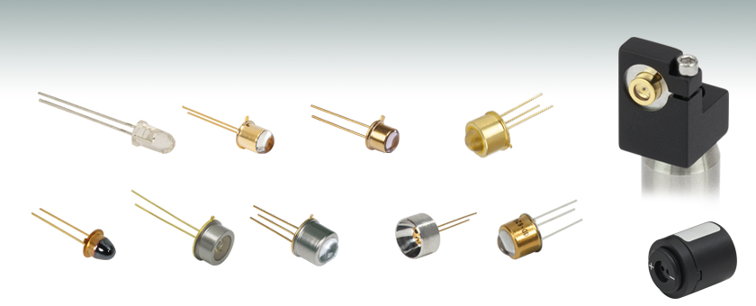
- LEDs in the UV, Visible, or IR Spectral Ranges
- Broadband Light Sources
- Compatible with Versatile LED Mounts
T-1 3/4 Package
TO-39 Package with Window
TO-18 Package
with Glass Lens
TO-18R Package
Application Idea
TO-39 Package
with Glass Lens
TO-18 LED Shown
in LEDMF Mount
(Post Not Included)
TO-39 Package UV LED with Ball Lens
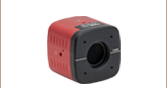
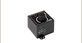
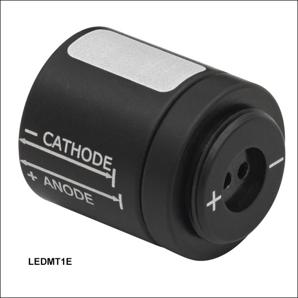
LEDMT1E
USB-Powered
LED Mount
TO-18 Package
with Glass Cover
TO-46 Package
with Glass Lens
TO-39 Package
UV LED with Aspheric Glass Lens


Please Wait
Click to Enlarge
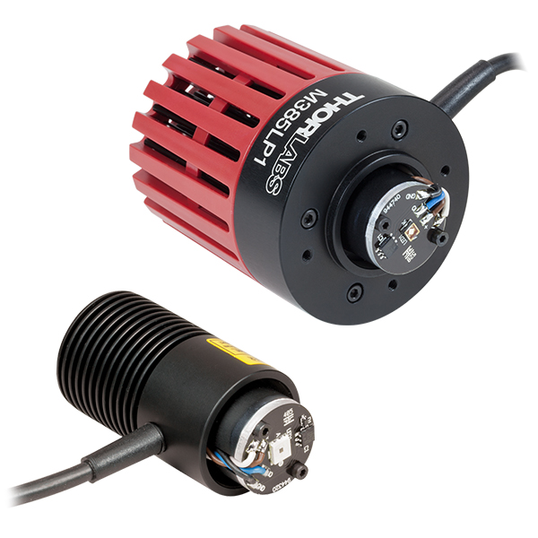
LED630E Red LED Mounted in an LEDMT1F USB-Powered LED Mount Using an LMR05 Lens Mount
Features
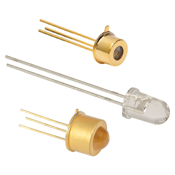
- Unmounted LEDs in TO-Can Packages
- Wide Range of Center Wavelengths Available (See Table to the Right)
- Single-Color LEDs from 250 nm to 4.4 µm
- Multi-Color LEDs
- White Light LEDs (430 - 660 nm)
- LED Output Powers Ranging from 6 µW to 170 mW
- Select LEDs Sold in Packs of 5
- Mounting Options (Post Mountable or SM Threaded) and LED Socket Available
- Other LED Configurations Include Mounted LEDs, Fiber-Coupled LEDs, and Collimated LEDs (See LED Selection Guide Tab for Full List of Options)
Light-emitting diodes (LEDs) are compact, energy-efficient light sources that can emit light over a wide range of wavelengths. Thorlabs offers unmounted LEDs for center wavelengths from 250 nm to 4.4 µm. These unmounted LEDs are available epoxy-encased in T-1 3/4 packages or in a variety of TO-can style housings, including TO-18, TO-46, TO-39, Ø9 mm, and TO-18R. A selection of the UV LEDs have ball lenses that focus the output into a narrow viewing half angle of no more than 7.5°, while the other LEDs that are in TO-can style packages are offered with flat windows, glass covers, glass lenses, or parabolic retroreflectors.
Use the Quick Links table to the right to view LEDs within a specific wavelength range. General information about each LED is provided in the tables to compare specifications. Complete specifications and a spectrum plot are provided in the spec sheets, which can be accessed by clicking on the red docs icon (![]() ) next to the Item # below.
) next to the Item # below.
Due to unmounted LEDs typically having significant divergence angles, the output light frequently needs to be focused through a lens for use within an experimental setup. Aspheric condenser lenses (available uncoated for 380 - 2100 nm or with an AR coating for 350 - 700 nm or 650 - 1050 nm) are ideal for collimating the light from our unmounted LEDs with a center wavelength from 405 nm to 1600 nm. Unmounted LEDs with center wavelengths from 1650 nm to 4400 nm feature parabolic reflectors that reduce the output divergence angle. See the Collimation tab for more information on collimating the light from an LED. The Characterization tab describes sample methods and equipment for characterizing the light output from the majority of LEDs offered on this page. To discuss other options, please contact Tech Support.
| If you do not see an LED with the wavelength/color, optical power, or viewing angle desired, please contact Tech Support, and we will work to obtain one for you and consider adding it to our permanent offerings. |
Light-Emitting Diode (LED) Characterization Methods
Thorlabs offers the items and equipment necessary to characterize the light emission properties of the majority of LEDs sold on this page. The different specifications which may be determined using the methods and equipment below are:
- Spectral Distribution
- Full Width at Half Maximum (FWHM)
- Radial Intensity Distribution
- Half Viewing Angle
- Forward Radiated Optical Power
- Total Optical Power
Measurement Technique for Spectral Distribution and FWHM
A CCS200(/M) Fiber-Coupled Compact Spectrometer connected to a computer can be used to measure the spectral response of LEDs in the UV*/visible wavelength range (200 - 1000 nm; for LEDs emitting in NIR, use the OSA202C). The LED may be powered by an LD1255R Laser Diode Driver operating in constant current mode. The light from the LED is focused by an LB1761 Bi-Convex Lens, f = 25.4 mm, into a Ø50 µm core multimode fiber patch cable with SMA905 connectors attached to the spectrometer.
| # | Imperial Item # |
Metric Item # |
Product Description | Qty. |
|---|---|---|---|---|
| Visible LEDs (245 nm - 940 nm) | ||||
| 1 | - | LED (245 nm - 940 nm)a | 1 | |
| 2b | CCS200 | CCS200/M | Compact Spectrometer, Extended Range: 200 - 1000 nm |
1 |
| 3 | SM1SMA | SMA Fiber Adapter Plate | 1 | |
| 4 | M14L01 | Ø50 µm, SMA905 Fiber Patch Cable | 1 | |
| NIR LEDs (635 nm - 1650 nm) | ||||
| 1 | - | LED (635 nm - 1650 nm)a | 1 | |
| 2 | OSA202C | Optical Spectrum Analyzer, Wavelength Range: 600 - 1700 nm |
1 | |
| 3 | SM1FC | FC/PC Fiber Adapter Plate | 1 | |
| 4 | M42L01 | Ø50 µm, FC/PC Fiber Patch Cable | 1 | |
| General | ||||
| 5 | S05LEDM | SM05 LED Mount | 1 | |
| 6 | LB1676 | N-BK7 Bi-Convex Lens, Ø1", f = 100.0 mm | 1 | |
| 7 | SM1L03 | SM1 Lens Tube, 0.3" Thread Depth | 1 | |
| 8 | CXY1Ac | XY Translating Lens Mount for Ø1" Optics | 1 | |
| 9 | CP33 | CP33/M | SM1-Threaded 30 mm Cage Plate | 1 |
| 10 | CP32 | CP32/M | SM05-Threaded 30 mm Cage Plate | 1 |
| 11 | ER8-P4 | Cage Assembly Rods, 8" Long, Ø6 mm, 4 Pack | 1 | |
| 12 | TR2 | TR50/M | Ø1/2" x 2" (50 mm) Stainless Steel Optical Post | 1 |
| 13 | UPH3 | UPH75/M | Universal Post Holder, 3" (75 mm) | 1 |
| 14 | MB612 | MB1530/M | Aluminum Breadboard, 6" x 12" (150 mm x 300 mm) |
1 |
| 15 | HW-KIT2 | HW-KIT2/M | 1/4"-20 (M6) Cap Screw and Hardware Kit | 1 |
*Please note that the CCS200 spectrometer cannot be amplitude calibrated below 380 nm. When performing broadband power measurements, a large difference in the relative response of the system from the UV to the visible inhibits reliable power readings in the UV.
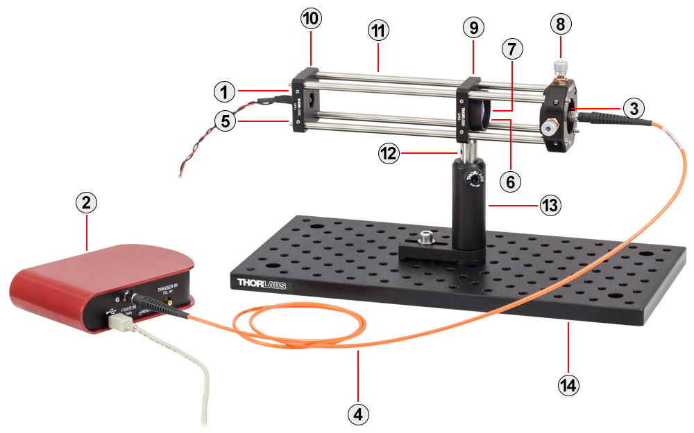
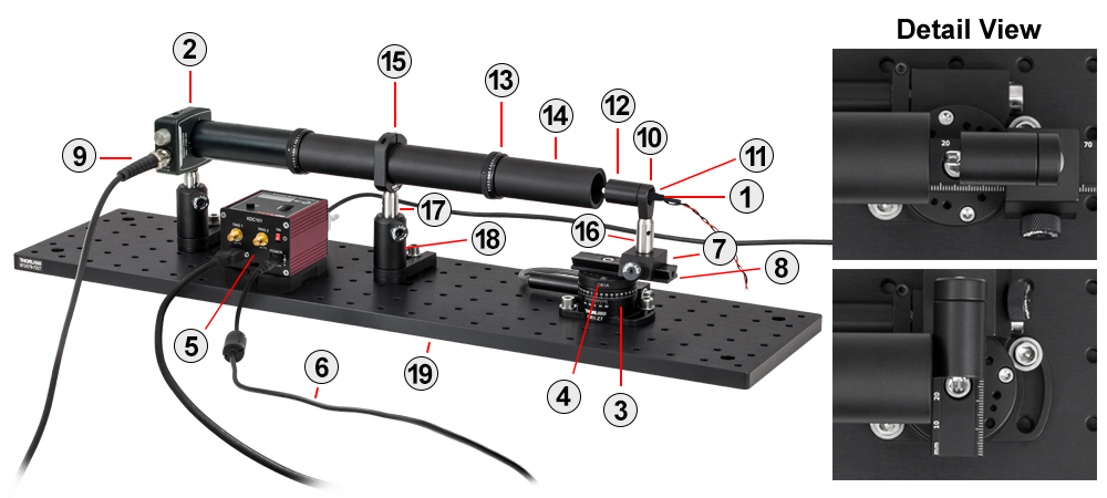
Measurement Technique for Radial Intensity Distribution and the Half Viewing Angle
To make a measurement of the intensity pattern as a function of angle, the LED can be rotated on an axis perpendicular to the axis along which the emitted light intensity is the greatest. Goniometric rotation of the LED is achieved by mounting the LED on a post attached to a Motorized Rotation Stage so that the rotation axis goes through the light emitting surface of the LED. The stage is controlled by a brushed DC servo motor, such as our KDC101, while the LED is powered by an LD1255R Laser Diode Driver. The radiated light is detected using either a Si or Ge Photodetector, DET36A2 or DET30B2 respectively, located approximately 12 inches from the LED. The S05LEDM LED Mount is recessed within the SM05M10 Lens Tube such that the front of the LED is centered above the center of the rotation stage. To keep stray or scattered light from hitting the detector, SM1 Lens Tubes are attached to the detector that extends to just short of the LED. Two SM1D12C Iris Apertures are placed along the path from the LED to the detector. The iris closer to the LED has an aperture diameter of 10 mm while the aperture nearest the detector has a diameter of 3 mm.
As the LED rotates, the output of the photodiode detector, which is proportional to the light intensity, is recorded for each angular position using a data acquisition card. The LED is rotated from +90° to -90°, where 0° approximately corresponds to when the axis of maximum intensity is parallel to the detector axis. The half viewing angle specification is determined by the angle that corresponds to a 50% drop from the maximum detector output.
| # | Imperial Item # |
Metric Item # |
Product Description | Qty. |
|---|---|---|---|---|
| Visible LEDs (365 nm - 1070 nm) | ||||
| 1 | - | LED (365 nm - 1070 nm)a | 1 | |
| 2 | DET36A2 | Silicon Photodetector Wavelength Range: 350 - 1100 nm |
1 | |
| NIR LEDs (850 nm - 1750 nm) | ||||
| 1 | - | LED (850 nm - 1750 nm)a | 1 | |
| 2 | DET30B2 | Germanium Photodetector Wavelength Range: 800 - 1800 nm |
1 | |
| General | ||||
| 3 | - | Motorized Rotation Stage | 1 | |
| 4 | CR1A | CR1A/M | CR1 Adapter Plate | 1 |
| 5 | KDC101 | K-Cube™ DC Servo Motor Controller | 1 | |
| 6 | KPS201b | 15 V Power Supply for One K- or T-Cube™ | 1 | |
| 7 | RC1 | Rail Carrier, 1" x 1" | 1 | |
| 8 | RLA0300 | RLA075/M | Dovetail Optical Rail, 3" (75 mm) | 1 |
| 9 | 2249-C-36 | BNC Coaxial Cable, BNC Male to BNC Male | 1 | |
| 10 | LMR05S | LMR05S/M | Ø1/2" Lens Mount with Internal and External SM05 Threads | 1 |
| 11 | S05LEDM | SM05 LED Mount | 1 | |
| 12 | SM05M10 | SM05 Lens Tube without External Threads, 1" Long | 1 | |
| 13 | SM1D12C | Graduated, Ring-Activated SM1 Iris Diaphragm | 2 | |
| 14 | SM1L30 | SM1 Lens Tube, 3" Thread Depth | 4 | |
| 15 | SM1RC | SM1RC/M | SM1 Series Slim Lens Tube Slip Ring | 1 |
| 16 | TR1 | TR30/M | Ø1/2" x 1" (30 mm) Stainless Steel Optical Post | 1 |
| 17 | TR2 | TR50/M | Ø1/2" x 2" (50 mm) Stainless Steel Optical Post | 2 |
| 18 | UPH2 | UPH50/M | Universal Post Holder, 2" (50 mm) | 2 |
| 19 | MB624 | MB1560/M | Aluminum Breadboard, 6" x 24" (150 mm x 600 mm) |
1 |
| 20 | HW-KIT2 | HW-KIT2/M | 1/4"-20 (M6) Cap Screw and Hardware Kit | 1 |
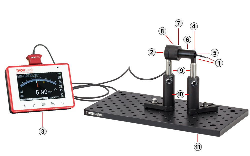
Measurement Technique for Determining the Forward Radiated Optical Power
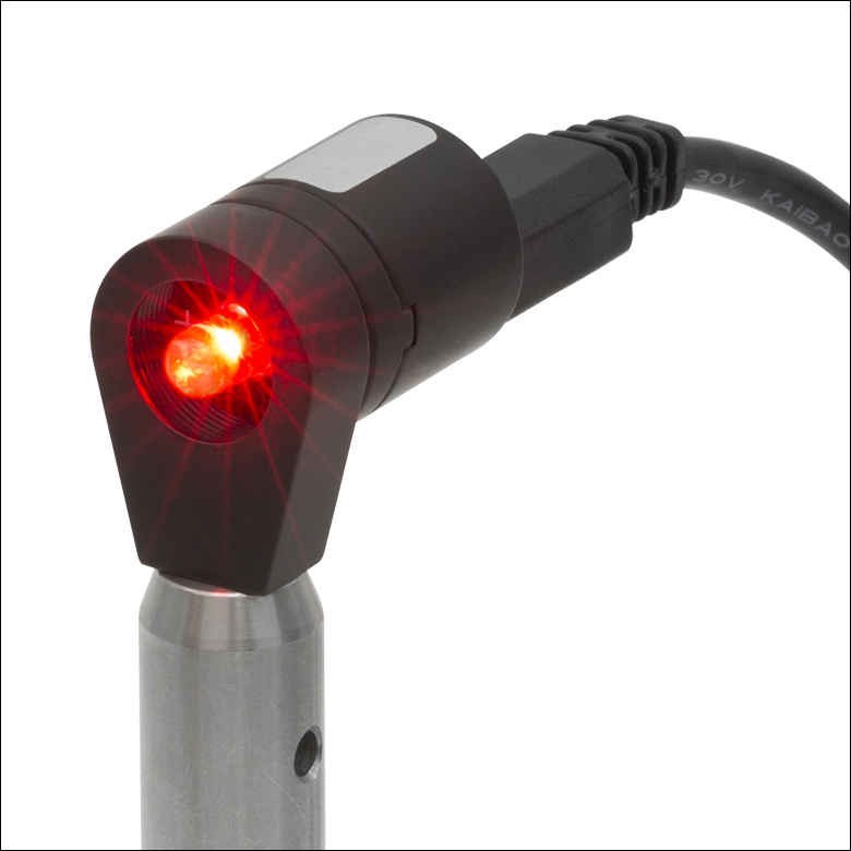
The total forward radiated power of the LED can be measured using a PM400 Power and Energy Meter with an S120VC Power Sensor (for UV/visible wavelength LEDs) or S122C Power Sensor (for NIR LEDs). See the picture below.
| # | Imperial Item # |
Metric Item # |
Product Description | Qty. |
|---|---|---|---|---|
| Visible LEDs (245 nm - 1070 nm) | ||||
| 1 | - | LED (245 nm - 1070 nm)a | 1 | |
| 2 | S120VC | Photodiode Power Sensor, Si Wavelength Range: 200 - 1100 nm |
1 | |
| NIR LEDs (780 nm - 1750 nm) | ||||
| 1 | - | LED (780 nm - 1750 nm)a | 1 | |
| 2 | S122C | Photodiode Power Sensor, Ge Wavelength Range: 700 - 1800 nm |
1 | |
| General | ||||
| 3 | PM400 | Touch Screen Power and Energy Meter | 1 | |
| 4 | LMR05S | LMR05S/M | Ø1/2" Lens Mount with Internal and External SM05 Threads | 1 |
| 5 | S05LEDM | SM05 LED Mount | 1 | |
| 6 | SM05M10 | SM05 Lens Tube without External Threads, 1" Long | 1 | |
| 7 | SM1A1 | Adapter with External SM05 Threads and Internal SM1 Threads |
1 | |
| 8 | SM1L05 | SM1 Lens Tube, 0.5" Thread Depth | 1 | |
| 9 | TR2 | TR50/M | Ø1/2" x 2" (50 mm) Stainless Steel Optical Post | 2 |
| 10 | UPH3 | UPH75/M | Universal Post Holder, 3" (75 mm) | 2 |
| 11 | MB612 | MB1530/M | Aluminum Breadboard, 6" x 12" (150 mm x 300 mm) |
1 |
| 12 | HW-KIT2 | HW-KIT2/M | 1/4"-20 (M6) Cap Screw and Hardware Kit | 1 |
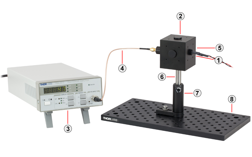
Measurement Technique for Determining the Total Optical Power
The total optical output power of an LED can be measured using an integrating sphere. The radiated light is detected using either a Silicon (for UV or visible wavelength LEDs) or InGaAs (for NIR LEDs) Photodiode and Integrating Sphere, such as the IS200 with SM05PD2A or IS210C, respectively. The sphere may be calibrated with a laser source such as the Thorlabs CPS635R Laser Diode Module. The output of the photodiode can be amplified and measured using our PDA200C Benchtop Photodiode Amplifier.
| # | Imperial Item # |
Metric Item # |
Product Description | Qty. |
|---|---|---|---|---|
| Visible LEDs (245 nm - 1070 nm) | ||||
| 1 | - | LED (245 nm - 1070 nm)a | 1 | |
| 2 | IS200 SM05PD2A |
Ø2" Integrating Sphere, Si Photodiode, Wavelength: 200 - 1100 nm |
1 | |
| NIR LEDs (850 nm - 1750 nm) | ||||
| 1 | - | LED (850 nm - 1750 nm)a | 1 | |
| 2 | IS210C | Ø2" Integrating Sphere, InGaAs Sensor, Wavelength Range: 800 - 1800 nm |
1 | |
| General | ||||
| 3 | PDA200C | Benchtop Photodiode Amplifier | 1 | |
| 4 | CA2806 | SMA Coaxial Cable, SMA to BNC | 1 | |
| 5 | S05LEDM | SM05 LED Mount | 1 | |
| 6 | TR2 | TR50/M | Ø1/2" x 2" (50 mm), Stainless Steel Optical Post | 1 |
| 7 | UPH3 | UPH75/M | Universal Post Holder, 3" (75 mm) | 1 |
| 8 | MB612 | MB1530/M | Aluminum Breadboard, 6" x 12" (150 mm x 300 mm) |
1 |
| 9 | HW-KIT2 | HW-KIT2/M | 1/4"-20 (M6) Cap Screw and Hardware Kit | 1 |
Video Insight: Collimate Light from an LED
Collimating light from an LED or other large, incoherent source can be a surprisingly challenging task. The emitter’s size and the collimating lens’ focal length and numerical aperture (NA) all influence the characteristics of the collimated beam. It can also be hard to know when the lens is positioned optimally. In this video, two lenses with different NAs and focal lengths are used to demonstrate a couple of collimation approaches. In addition, the emerging image of the emitter and other typical features of beams provided by collimating lenses are explored.
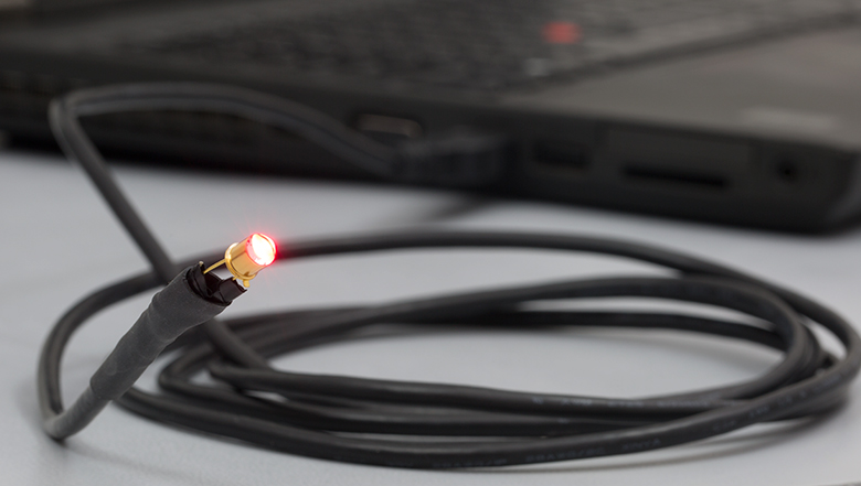
Do-It-Yourself USB LED
A Universal Serial Bus (USB) port can be used to quickly power many of the Light Emitting Diodes (LEDs) on this page for temporary use. USB ports are used in a variety of applications like charging batteries and transferring data; they are commonly found on computers, but they are increasingly found on other electronic devices, and even incorporated into wall outlets. This tab presents a step-by-step tutorial to take advantage of this port in order to power an LED. Take note of the spec sheet for the LED being used; if its Typical Forward Voltage is listed higher than 5 V, the LED will not be able to be powered by a USB port (this is explained using Equation 2 below). Spec sheets can be downloaded by clicking on the (![]() ) icon next to desired item.
) icon next to desired item.
Example Application
It is possible to create a continuous lighting setup using an LED525L from the Thorlabs catalog, powered by a USB port. A
100 Ohm resistor should be used for this system. For an explanation on how this was determined, see Equations 3 and 4 below.
Warning
This tutorial contains instructions that require the creation of an electrical circuit, including the use of a soldering iron. Please be advised that the user is fully responsible for following proper practices with regards to creating an electric circuit when following this procedure. For other LED power solutions, visit our selection of current controllers for LEDs
Procedure (Click Images for Details)
 If the chosen USB wire is repurposed with two ends, unplug both ends and cut off the non-Type A Male end, leaving as much slack on the Type A Male end as possible using Wire Cutters.
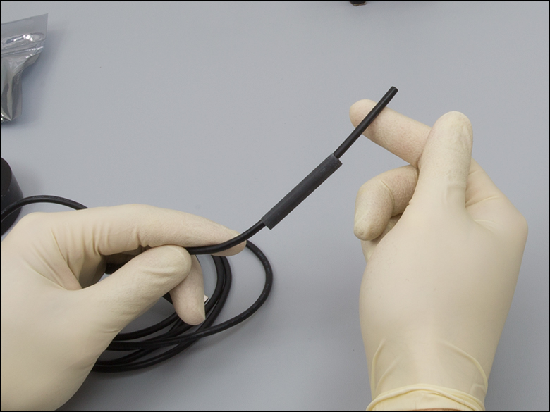 If heat shrink tubing will be utilized, place a length of two inches down the wire for later.
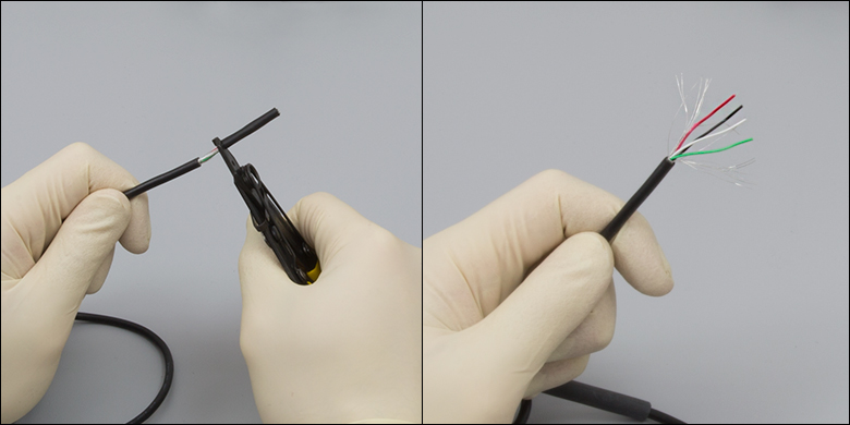 Strip the outer plastic about two inches from the end, being careful not to cut too far into the wire.
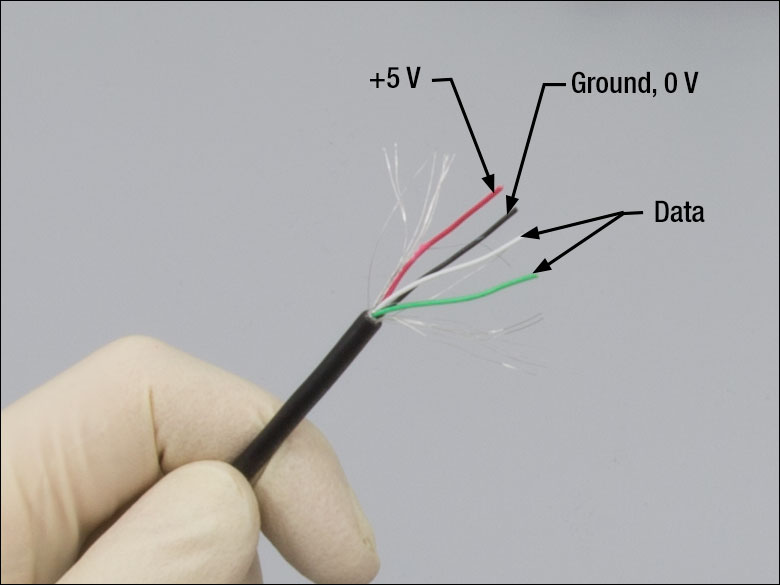 The wire will contain shielding and four smaller wires: Red (+5 V), Black (Ground, 0 V), White and Green. The latter two wires are used for data transfer.
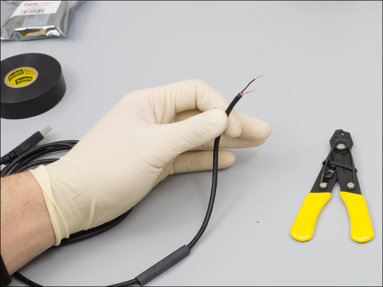 Cut away an inch of the red wire, any exposed shielding, and the white and green wires down to the main wire's remaining outer plastic while stripping the Red and Black wires to give enough room for a solder joint.
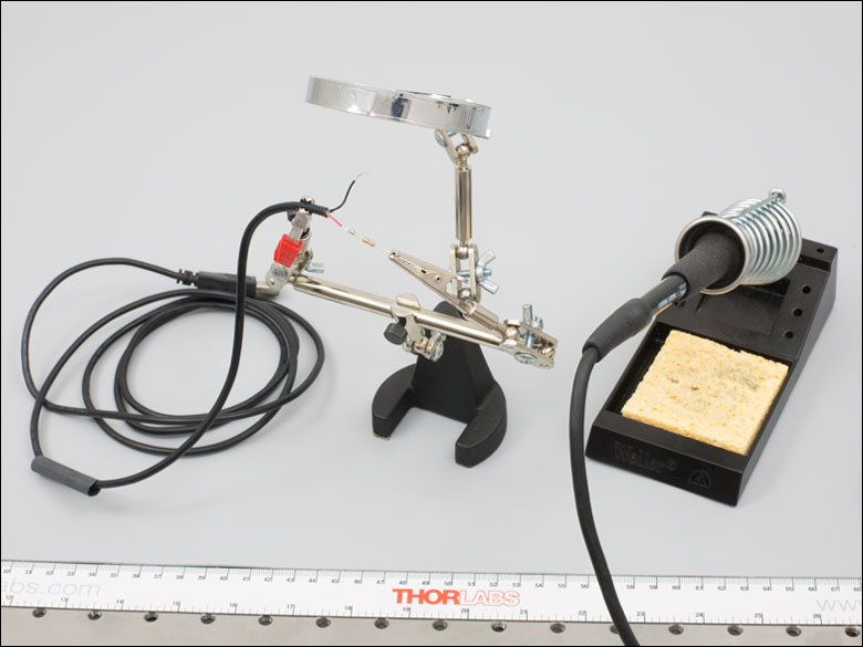 Solder one end of the resistor (resistors are bidirectional, either end will do) to the red wire. The end of the resistor's lead and the black wire should be roughly the same length.
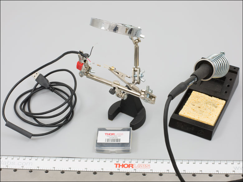 Find the positive pin on the LED, the anode, which can be found on the LED's Spec Sheet, and solder it to the resistor.
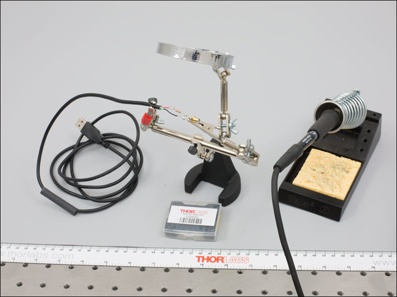 Solder the remaining, negative end of the LED, the cathode, to the black wire.
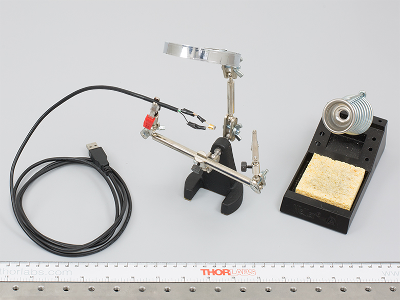 Once the solder has cooled, wrap each connection separately in a layer of electrical tape.
 Warning: Improper insolation of exposed metal can lead to shorting of the circuit, electrical failure, or fire.
 Either cover the wrapped wires in electrical tape, or, if heat shrink tubing was placed down the wire, slide it up over the connections, and slowly heat with a heat gun or hair dryer until it snugly fits over the connections.
Parts List
Components:
- An Unmounted LED
- A Type-A Male Connector USB Wire with Pigtails
- A Resistor (See Choosing a Resistor)
- (Optional) 5 VDC External Battery Pack (CPS1)
- (Optional) Repurposed USB with Type-A Male Connector (USB-C-36)
Tools:
- Wire Strippers
- Electrical Tape
- Soldering Iron
- Solder
- Helping Hand
- (Optional) Heat Shrink Tubing
- (Optional) Heat Gun or Hair Dryer
Choosing a Resistor
USB ports can produce up to 500 mA or higher in some cases, which is too much current for most LEDs. For this reason, an LED connected directly to a USB cable will burn out within a matter of hours. Placing a resistor before the LED in the circuit will reduce the current coming from the USB port, and allow the LED to operate.
To find the best resistor for the job, start with Ohm's Law, which gives the voltage across a wire,
V=IR (Equation 1),
where V is Voltage, I is Current, and R is Resistance.
V here will be the difference between our voltage output from our source (Vs ), and the forward voltage of our LED (Vf ), found on the chosen LEDs spec sheet. Vf can be thought of as a threshold the current needs to overcome to get the LED to light up. Replacing the difference into Equation 1 yields
(Vs-Vf )=IR (Equation 2).
I will match the operating current for our LED, found on the chosen LEDs spec sheet; rearranging the equation for R yields
R=(Vs-Vf )/I (Equation 3).
Choose the resistor that is the closest match rounding up.
Looking at the specification sheet for the LED525:, the Maximum DC Forward Current is 30 mA and the Typical Forward Voltage is 3.0 Va. To keep the LED running at a current lower than the maximum, 20 mA will be chosen for the current. Knowing that a USB port has a 5 V potential, Equation 3 results in the following:
R=(Vs-Vf )/I = (5 V-3 V)/.02 A = 100 Ohm (Equation 4).
A 100 Ohm resistor is a standard size, so no rounding up is needed.
Portable Battery Pack
This system can be mobile with the addition of a 5 VDC External Battery Pack (CPS1), which is sold by Thorlabs. This device acts just like any other USB Type A female port. Alternatively, a battery holder can be hard wired on as long as the batteries supply a higher voltage than the LED's forward voltage Vf . In the case of adding a battery holder, Equation 3 is still applied, except changing the Vs to the batteries voltage. It may also be beneficial to add a switch to your circuit, so that way the LED can be switched on and off without needing to remove it from the power supply.
Powering Multiple LEDs
If more than one LED is needed, they can be combined in either series or parallel. If placed in series, LEDs' Vf will stack, requiring a larger Vs . A parallel configuration is more advantageous for LEDs; in this configuration, more current is needed from the power source, but the Vf can be satisfied on an individual basis by Vs . While in parallel, it is also very important that each LED has its own resistor, calculated as if each LED was independently connected to the battery, or the system will risk a total burn out if one LED fails, as each remaining LED would attempt to bear the current of the dead LED.
| Posted Comments: | |
Michael Simmonds
(posted 2024-08-25 09:08:44.793) Hi, need 410 nm for oxygen measurement in blood.
Any chance you have old stock? cdolbashian
(posted 2024-08-26 10:00:46.0) Thank you for reaching out to us with this inquiry. Unfortunately, we do not have any of these left in stock following obsolescence. I have reached out to you directly in an attempt to find a suitable alternative. Germán Cortes
(posted 2024-07-31 11:08:01.56) Hello, excuse me, would it be possible for you to send me the 'LED840L' diode in the LTspice electronic simulator, please? The thing is, I am working on a project where I want to create a current regulator, and for that, I need the LED in the LTspice simulator since I cannot find it. hchow
(posted 2024-08-01 06:55:55.0) Dear Mr. Cortes, thank you for your feedback. We unfortunately do not have any LTspice files for the LED840L. I will personally reach out to you to provide further details. Thank you. Ariel Nachman
(posted 2024-04-17 21:22:14.217) Typical voltage and typical current have some issues:
1. voltage Vs current is not meeting the specification
2. What is the Current Vs forward current graph ? hchow
(posted 2024-04-18 05:48:34.0) Dear Mr. Nachman, thank you for your feedback. I will personally address the issues you are facing with the LED4400P in an email to you. Thank you. James Piao
(posted 2023-05-10 17:27:58.727) Hello,
I ordered this LED and two others. This one is much off the specs (only 0.1 mw, while 1670 nm LED emit 0.6 mw at same driving conditions). This one may be a defect one. hchow
(posted 2023-05-12 09:16:44.0) Dear Mr. Piao, thank you for your feedback. I am sorry to hear that your LEDs aren't performing up to your expectations. I will personally reach to you to see how we can solve this issue for you. Thank you. user
(posted 2023-01-24 03:21:33.367) Hi, I am working with the LED850LW. I am trying to expose the light-emitting chip itself. I have opened up the LED can with a can opener, but it appears that the chip itself is encased in some kind of epoxy. Do you know if there is any way to remove the epoxy? Or alternatively, do you know what material the epoxy is made out of? Do you also sell any LEDs where the chips are not encased in any epoxy? Thank you! dpossin
(posted 2023-01-24 08:00:39.0) Dear customer,
Thank you for your feedback. Unfortunately since we just act as a reseller for the unmounted LEDs, we do not have any influence on the packaging. As an alternative you might have a look at our unmounted chips: https://www.thorlabs.de/thorproduct.cfm?partnumber=M850D3
I am reaching out to you to discuss this in more detail. park yk
(posted 2022-10-06 13:39:44.843) Hello!
Korea Mr. Park
Can I see the maximum output test video? The purchase Proceeded. wskopalik
(posted 2022-10-10 07:58:31.0) Thank you very much for your inquiry!
Unfortunately, we do not have any videos showing this test. But we might have additional information which could be helpful.
I will contact you directly to provide further assistance. Sami Liedes
(posted 2022-05-17 07:46:53.313) Hi! I have a hobby project—to measure/estimate human cone cell responses—in which I'd need to produce different combinations of visible light wavelengths (RGB only doesn't cut it) for observation with human eyes. Your LEDs in the visible light range (and light mixing rods etc) look potentially suitable, but since I'm new to optics, I thought I'd ask what you'd recommend for this use or if you'd even consider them safe for this kind of thing. The electronics side I believe I can handle.
Basically, I would want to control the (approximate) luminosity of the 10-or-so different wavelength LEDs, mix the light and present it to a human eye, either via an eyepiece or on some diffuse white surface, with the goal of finding different (known) spectra that produce the same perception. Obviously I'd be interested in rather small output powers. Also, do you think a light mixing rod is suitable for this? Or do you think one of your diffusers would be good enough? mdiekmann
(posted 2022-05-17 05:00:12.0) Thank you for contacting us! As you selected not to be contacted, could you reach out to our Scandinavian Tech Support team at techsupport.se@thorlabs.com? We will be happy to support you with finding the best solution for this application. Mark Sudberry
(posted 2022-03-12 00:01:15.467) I need this wavelength 1950 in To-18 glass dome lens. soswald
(posted 2022-03-15 06:24:03.0) Dear Mark,
thank you for your feedback. I have reached out to you directly to discuss your application and requirements in more detail. Jakob R
(posted 2022-03-07 03:29:46.407) What is the angular distribution of the following leds? (preferably graphed) LED1800P, LED1900P, LED2050P and LED2350P. They are not specified in the datasheet. And what is the emitter size of those leds? hkarpenko
(posted 2022-03-14 07:55:02.0) Dear Jakob,
thank you very much for your feedback. I will contact you directly to discuss this with you. Parvez Akhtar
(posted 2022-03-07 15:55:22.167) what is the active area of the LED680? mdiekmann
(posted 2022-03-10 06:27:03.0) Thank you for your question. Unfortunately, we cannot publish this information. As you preferred not to be contacted, please reach out to your local tech support for more information. mdiekmann
(posted 2022-03-10 06:27:03.0) Thank you for your question. Unfortunately, we cannot publish this information. As you preferred not to be contacted, please reach out to your local tech support for more information. SITI HAJAR AB AZIZ
(posted 2022-02-17 13:52:20.337) Hi, I'm looking for the White LED, and now comparing to buy mounted or unmounted. Mounted LED needs LED driver to function, right? It is opposite to unmounted LED.
Could you provide me details which type I should use for commercial White LED?
I need the LED for illumination and data communication.
Thank you. dpossin
(posted 2022-02-18 04:50:23.0) Dear Hajar,
Thank you for your feedback. In general for every LED you need a suitable driver. We offer drivers only for our mounted LEDs. I am reaching out to you in order to discuss in more detail possible options with you. John Coates
(posted 2022-01-09 15:40:21.833) I am working on a team where we are developing a UV-based spectral sensor. We wish to make an addressable LED array to serve as a scanning UV source. The goal would be to make the array with LED devices that cover 250nm to 400nm with a wavelength separation of 10nm. Can Thorlabs work with us to produce such an array. This will be for a high volume medical application... initially we need to prototype the device... but eventually we would integrate this into a handheld measurement system, to be sold in quantities of 1000 to 100,000.
Please advise whether Thorlabs is able to provide such a device. Our company has experience in making commercial instrumentation... company name is Lightsense...based in Tucson, AZ.
Thank you... John Coates cdolbashian
(posted 2022-01-10 12:02:27.0) Thank you for reaching out to us at Thorlabs with this OEM request. I have reached out to you directly, and put you in contact with our OEM/Solutions team, who will discuss the specifics for your custom LED solution. 娇娇 范
(posted 2021-08-19 09:30:22.8) 咨询产品LED430L的辐射稳定性情况、寿命情况,希望获得相关数据,比如曲线图。 Rod Wesson
(posted 2021-08-02 17:10:18.22) Hi
I think the spec sheet is wrong for this device as it says on the drawing bottom view but the pins and tab appear to show top view. Also could you please confirm if there is any preference on connecting the case to either the cathode, anode or just the shield of the controller as the case on the LED340W appears to be connected to the anode according to its drawing. Thanks dpossin
(posted 2021-08-16 09:28:11.0) Dear Rod,
Thank you for your feedback. We correct the specsheet. I am reaching out to you in order to provide further information. sandeep kumar
(posted 2021-05-17 17:34:41.89) We have purchased these led a year ago. I want to know, what material is used to make the LED legs (cathode and anode). It will be helpful if you can provide the details. MKiess
(posted 2021-05-21 04:30:11.0) Dear Sandeep, thank you very much for your inquiry. The material of the LED591E legs is SPCC steel. Sagar S
(posted 2021-04-30 15:08:34.597) Hi, Any reference application circuit to drive the LED1900P? The Spec sheet doesn't have the voltages information, if you could provide them - would be helpful. Thanks! dpossin
(posted 2021-05-03 05:18:04.0) Dear Sagar,
Thank you for your feedback. The forward voltage in the QCW mode is rated to 0.5-2.5V at 200mA driving current. A suitable LED driver would be the DC2200. I am reaching out to you to further discuss this. Ulrich Leischner
(posted 2020-12-09 10:33:50.493) Hello
We would need this device with the colors green, red, and IR (preferably with light >1050nm, this would be an 1200nm-IR-LED). Would this be possible to generate such a product?
Regards
Ulrich Leischner wskopalik
(posted 2020-12-10 09:01:32.0) Thank you very much for your inquiry!
Multi-Color LEDs are unfortunately mainly designed for illumination applications and are therefore mainly available with LEDs emitting visible light.
I will however check if such a custom is possible and will contact you directly. Andrew Davies
(posted 2020-08-10 17:57:44.96) What is the emitter size for LED528EHP, LED525L, LED528EHP, LED555L, and LED570L? MKiess
(posted 2020-08-11 09:14:10.0) Dear Andrew, thank you very much for your inquiry. I have contacted you directly to discuss the specifications in detail. Yanting Lu
(posted 2020-07-07 01:38:13.14) Ask for the curve of Forward Current vs. Forward Voltage MKiess
(posted 2020-07-08 06:42:32.0) This is an response from Michael of Thorlabs. Thank you very much for your inquiry. The general specifications can be found on our website at the respective product. For further information I have contacted you directly. jason Hu
(posted 2019-12-11 14:17:16.027) Why does 1450nm infrared LED, after lighting for a period of time (about 2 hours), reduce the luminous intensity by 30%? Is it related to the way of heat dissipation? If so, how to cool it?
Which is the main cooling surface of this led? dpossin
(posted 2019-12-12 10:18:20.0) Dear customer,
Thank you for your feedback. As the LED1450L has a power consumption of 50mW but emits an optical power of 5mW, the heat dissipation is 45mW. Therefore it is needed to introduce thermal management. I am reaching out to you in order to provide further information. Ludovic Angot
(posted 2019-08-05 03:51:22.137) Please review the spec sheet of your LEDRGBE RGB led, as of the date of posting it is incorrect: a 2 pins LED is shown in section 2.5 and with the wrong anode and cathode configuration. Also do you confirm that the max DC forward current (stated at 50mA) is valid for each individual RGB channels? MKiess
(posted 2019-08-07 08:55:09.0) This is a response from Michael at Thorlabs. Thank you very much for the feedback. You're absolutely right that this representation is incorrect. We will correct it immediately. The DC forward current of 50mA is valid for each individual RGB channels. Thank you very much for this information. Sanket Shah
(posted 2019-07-31 11:04:30.18) The spec sheet does not specify the electrical requirements of the LED4300P well enough, and the mechanical drawing is also unclear with the actual numbers not readable. I need to know if it can be operated at duty cycles in between the mentioned operating modes qCW & pulsed. Also missing is the maximum voltages that are acceptable. dpossin
(posted 2019-08-29 06:58:13.0) Hello Sanket,
Thank you for your feedback! We are currently updating the manual in question to achive a better usability for our customers. We recommend using Quasi Continues Wave mode with a duty cycle 50% or 25% to obtain maximum average optical power and short Pulse modes to obtain maximum peak power. Hard CW mode is not recommended. The maximum voltage for qCW mode @ 2A is 0.8V. I hope that helps. user
(posted 2019-04-02 12:29:08.32) Could you please help to answer the following questions regarding LED470L.
What is the raw LED size?
What is the focal length of its ball lens?
Is it possible to get Zemax file of LED470L?
Thanks,
Paul Huang
Principal Optical Research Engineer
Panduit Corp.
6200 W 175th St
Tinley Park, IL 60477
Tel: (708) 532-1800 x 81137
Email: yuh@panduit.com swick
(posted 2019-04-08 04:19:21.0) This is a response from Sebastian at Thorlabs. Thank you for the inquiry.
The chip size for LED470L is 1.3 x 1.3 mm.
Unfortunately, we have no data for the ball lens and there is no Zemax file available for this LED.
I contacted you directly to provide assistance. kkmion
(posted 2018-08-10 10:06:17.557) Can the Quasi-CW LED be driven by LEDD1B? YLohia
(posted 2018-08-13 12:14:47.0) Thank you for contacting Thorlabs. Yes, the LED2350P can be driven by the LEDD1B. You would, however, have to perform the wiring yourself. Please note that the rise/fall time of LEDD1B is ~350 us in the Trigger Mode. lylaana
(posted 2018-01-25 09:32:05.387) 1. Optical Output Power is the total power before the lens or the power after the lens?
2. Since it’s a tiny lens, the light collimating efficiency can't be very good,how much would that collimating efficiency be about?
3. Do you have the distribution figure before collimating for LED450L,the LED chip? So I can decide how the distribution is changing,or is it worth to sacrifice the LED power?
4. What's the best you can do to achive a much better collimated LED with such conpact package? Or should I say is it possible?
THANKS. nbayconich
(posted 2018-02-16 09:42:44.0) Thank you for contacting Thorlabs. The optical power is specified after the lens or window in these types of LED packages. We do not specify a collimating efficiency for use with an additional lens, the ability to collimate an LED will depend on the divergence and chip size of the LED however it is not possible to perfectly collimate an LED source in the same way a laser diode can be.
Please see our spec sheet located below for more information about the intensity distribution vs. angle below.
https://www.thorlabschina.cn/_sd.cfm?fileName=QTN015134-S01.pdf&partNumber=LED450L
If you use an AR coated lens to collimate this LED your loss in power should be reduced to a minimum. I recommend using one of the condenser aspheric lenses to collimate these LED's, and if the intensity distribution is not suitable for your application a diffused surface aspheric lens may be a better option.
https://www.thorlabschina.cn/newgrouppage9.cfm?objectgroup_ID=5812 user
(posted 2016-12-14 10:52:12.673) Hello,
do you have a plot of the wavelenght shift for 1050E LED as function of temperature? I would like to use it down to 77K. Thanks tfrisch
(posted 2016-12-15 12:49:59.0) Hello, thank you for contacting Thorlabs. Unfortunately, we do not have any test data at 77K. I have doubts about whether the device may work at all at such low temperatures. thomas.nappez
(posted 2015-11-03 18:17:18.543) Hello,
I am currently using LEDs in pulsed operation with a driver circuit closed to the figure 1 of this link: http://elib.dlr.de/64324/1/mst075402_ledpiv_willert_2010.pdf
It works very well with the LED528EHP, with large increase of average optical output power. However when using the LED1450E (with adapted Vs), the output power is not increased (compared to continuous operation). Do you recommend a specific schematic for the pulse operation of InGaAs LEDs?
Best regards,
Thomas besembeson
(posted 2015-11-05 11:08:31.0) Response from Bweh at Thorlabs USA: I will look into this and follow-up with you via email. m.examinateur
(posted 2015-10-27 23:54:16.35) je vais utiliser le en mon projet
je suis en Algérie besembeson
(posted 2015-10-28 05:08:16.0) Response from Bweh at Thorlabs USA: I will contact you for any questions you may have regarding these LEDs. lcolchero
(posted 2015-01-14 21:46:05.28) Dear Sir:
In order to use this LED635L product I need even a more speficic datasheet, including pinout, SOA , pulsed operation, Temperature dissipation coefficient (ºC /W ), whether the 3 pin means optical power output fotodiode feedback posible as well as both katode - anode pins , Max switching frequncy, etc. Without this, it is useless to start designing anything , even the PCB I have in mind to design to this...
Could you provide a more complete datasheet please?
Many thanks in advance
Luis jlow
(posted 2015-01-20 02:37:30.0) Response from Jeremy at Thorlabs: We will look into including more information on the LED. In the meantime, we will contact you directly to provide more information on the LED. kevin.murphy
(posted 2014-02-17 18:13:15.003) Hi, is there any mount, that is compatible with the S1LEDM, available for a 3mm T1 packaged LED? Thanks cdaly
(posted 2014-02-25 04:02:07.0) Response from Chris at Thorlabs: Thank you for your feedback. At the moment we do not have an adapter which will allow a T1 package LED to be mounted in the S1LEDM or any of our other LED mounts. I apologize for any inconvenience this may cause. We will look into adding such an adapter in the future. mc.guacheta177
(posted 2013-10-28 08:11:58.907) Hi, I am a researcher at the Los Andes University and I am working with the infrared spectrum. I would like to know if there is any adaptation or conditioning circuit so I can use element LED4300P. Thank you very much. jlow
(posted 2013-10-29 14:46:00.0) Response from Jeremy at Thorlabs: We do not have an operating circuit available for the LED. However, you can use a constant current source (we recommend that this be driven with a quasi-CW or pulsed signal) to drive this LED. I will contact you to provide more information on this. a.andreski
(posted 2013-10-16 21:37:24.707) Hi,
Do you know what is the emitter area of the 370E (I suppose all the unmounted LEDs here are single-emitter sources)?
Aleksandar pbui
(posted 2013-10-31 04:16:28.0) Response from Phong at Thorlabs: The emitter area of the single-emitter LED370E is 350um x 350um. kevinserg
(posted 2013-09-06 12:05:54.977) Good afternoon.
I have some questions about LED2350P.
1)There is LED2350P Package TO-18(with Reflector) drawing on 3th page LED2350P datasheet. There is "window" on top LED2350P Package on the drawing. Word "window" is red color.
But we buy 2pieces of LED2350P without any window. Why there isn`t window on top our LED2350P? Now we place an order on 1 piece of LED2350P in firm Eurolase (in Russia). Can you make LED2350P with protective window for us? Is this window option?
2) You should correct and write warning in LED2350P datasheet: "LED2350P anod is connected to the LED2350P Package!"
3) We use LED2350P in such pulse mode regime: twidth=5uS, tperiod=0.5Sec, Ipulse=1A. LED2350P is mounted on heatsink. Can I use these pulse mode parameters for LED2350P? I can`t make twidth=1uS, as recommended in LED2350P datasheet.
Best regards, Sergey. jlow
(posted 2013-09-11 15:45:00.0) Response from Jeremy at Thorlabs: We are working on correcting the spec sheet and description issue. For #3, since you are increasing the duty cycle a bit, I would suggest decreasing the current slightly, to 0.95A. kevinserg
(posted 2013-01-22 10:00:44.447) Hello, please, answer my questions about LED370E and LED2350P. Sorry for my English.
1) Can LED370E be used in pulsed regime? There is no pulsed regime description in LED370E data sheet. What is Peak Pulsed Forward Current for LED370E? Are there data for forward voltage vs current and output power vs current for LED370E?
2) Are there data for forward voltage vs current and output power vs current for LED2350P?
3) What is the minimum distance between LED2350P and print circuit board? Can I mount LED2350P close to PCB?
4) Please, recommend IC (integrated circuit) for pulsed regime of LED2350P with parameters: pulse=1uS, period=500uS, pulse current=1A.
5) There is mismatch (mistake?) for pulsed regime figure of LED2350P:
I peak pulsed=2A (in file "LED2350P-SpecSheet.pdf")
I peak pulsed=1A (in file "1353.pdf") Where is true? tcohen
(posted 2012-09-05 13:43:00.0) Response from Tim at Thorlabs: The LED3100P has gone obsolete and has no direct replacement. If you are looking for the supporting documentation for this LED, this can be found by searching this product number. If you have any questions on this product, please contact us at techsupport@thorlabs.com. user
(posted 2012-08-31 02:39:00.0) Why can't I find the 3100 nm led? tcohen
(posted 2012-06-22 09:16:00.0) Response from Tim at Thorlabs: 5V will damage this diode. Please check the spec sheet for the forward voltage of this LED (~1.15V at 50mA). To use 5V you would need to include a resistor based on the desired current and forward voltage of the LED. With a forward voltage of 1.15V and 5V DC supply, you can see the series resistor needed to induce 50mA of current is just (5V-1.15V)/50mA. We recommend using a constant current source for these products. The bare LED has a half viewing angle of 15 degrees and the power is ~7.5mW. This is a divergent source and not very high power. However, care must always be taken when introducing optical elements into a beam path and any concerns of safety should be addressed with your laser safety officer. matt968
(posted 2012-06-20 12:01:40.0) LED1070E: Do I just apply 5V to the positive leg to get this thing to light up or are there other electrical components needed? Is the emission from this LED at 1070nm eyesafe? tcohen
(posted 2012-04-19 09:28:00.0) Response from Tim at Thorlabs: We do not have expected lifetime data for this LED. As always, you can prolong the life of your LED and reduce degradation by reducing the drive current and junction temperature. paul.lauria
(posted 2012-04-17 20:15:39.0) What is the expected lifetime of the LED470L? sharrell
(posted 2012-02-21 11:13:00.0) A response from Sean at Thorlabs:
Thank you for your feedback on the LED780E spec sheet. We will update the spec sheet with the correct plot as soon as the data is available. In the meantime, if you needed a normalized intensity curve for the LED780E, we have one on the catalog page located at http://www.thorlabs.com/catalogpages/V21/1345.PDF. Thank you for pointing out this error. lindsey.couvreur
(posted 2012-02-17 10:01:04.0) There is a mistake in LED780E data sheet: Typical LED591E Spectral Distribution appears instead. sharrell
(posted 2011-12-19 15:33:00.0) A response from Sean at Thorlabs: Thank you for your feedback. I am sorry that you had difficulty using our feedback form, and I have forwarded your comment to our webteam.
Regarding your feedback on our spec sheet plots, we will try to better integrate this information into our website, most likely using the "more info icon" you suggested. user
(posted 2011-12-19 14:51:07.0) Second try... your system said no key was found, would be nice to preserve the text if someone has an entry error...
Comment was that it is hard to get at the spectral plot provided on the Spec Sheets, please consider using the same method that is used for the Laser Diodes, where there is a "i" icon that triggers a pop up window with more data. It would work for me if that pop up gave a representative spectral plot. bdada
(posted 2011-12-13 19:25:00.0) Response from Buki at Thorlabs:
We are working on compiling the current vs output data for our LEDs and adding it to our website. Please email TechSupport@thorlabs.com so we can send you the data when we get it. user
(posted 2011-12-12 18:01:38.0) Is there data for current vs. output power for these LED's? In particular I'm interested in the LEDWE-15. Thank you. jjurado
(posted 2011-03-10 15:47:00.0) Response from Javier at Thorlabs to last poster: Thank you for submitting your inquiry. The UV-TOP LEDs have a rise time in the range 1-2 ns, which translates into a modulation frequency of 350 MHz to 175 MHz. Our LEDs for the visible and infrared range exhibit similar performance. Please contact Tech Support at techsupport@thorlabs.com for questions about a particular LED. user
(posted 2011-03-09 17:18:48.0) How fast can I modulate this LEDs? thanks Thorlabs
(posted 2011-01-19 10:18:43.0) Response from Javier at Thorlabs to ruelas: Thank you very much for submitting your feedback. We have reviewed the specifications and you are correct, the half-viewing angle spec for the LEDWE-50 is, in fact, 25 degrees. We will correct this information on the webpage accordingly. ruelas
(posted 2011-01-17 21:24:19.0) We have purchased several of the LEDWE-50 LEDs in the past and we have just noticed the viewing angle specification is inconsistent inconsistent; the webpage says the half-viewing angle is 50degrees, when it is actually 25 degrees, as specified in the catalog. Thorlabs
(posted 2010-08-20 10:37:02.0) Response from Javier at Thorlabs to smuehlen: Thank you for your feedback. The spectral distribution graphs are available on the spec sheets of our LEDs. I will send you a copy of the spec sheet of the LEDRGBE, which is also available here: http://www.thorlabs.com/Thorcat/16400/16400-S01.pdf smuehlen
(posted 2010-08-19 11:09:26.0) Are there any documents about the spectral distribution of the LEDRGBE as a function of the three applied voltages? This would be very helpful! Thorlabs
(posted 2010-08-06 18:10:50.0) Response from Javier at Thorlabs to sgourley: Thank you for your feedback. The typical full width at half maximum (FWHM) value for this diode is 100 nm. sgourley
(posted 2010-08-06 16:01:16.0) What is the bandwidth of the LED1300E? We have a replacement 1300nm design that is in the 50uW power level. We actually will need to mount in a TO-46 hole but appears it may be possible with this LED.
Thanks,
Sam G Thorlabs
(posted 2010-07-29 09:25:59.0) Response from Javier at Thorlabs to Vincent: Thank you for your feedback. We are currently looking into this for you. I will contact you directly once we have the details. vincent.thominet
(posted 2010-07-27 07:32:40.0) Please what are
the emitting area plane relatively to the housing
and the window glass and thickness?
Best regards
Vincent leichner
(posted 2009-11-05 12:41:39.0) A response from Lou at Thorlabs to abytas:
The LED341 is mid UV light emitting diode. It will emit light at approx 340nm (+/- 10nm) The window of the LED is a flat window and is not a lens. For your application the LED might proof best operation to involve a laser diode driver. You will have precise control over the light being emitted (power).
Im not sure how you want to use the emitting light. The light will diverge at about 15 degrees from the emitter. Typically such light would need to captured by collimation and focusing. But the type of optics required would depend on you use. abytas
(posted 2009-11-02 10:33:41.0) Dears,
I`m asking for power deep UV LED`s for our cardiac tissue luminescense explorations.
It might be Hemispherical Lens LED (T0-39) LED341
Sincere,
Dr. Algimantas Bytautas
Scientist
Kaunas Medical University BMTI
Eiveniu g. 4
LT-50161, Kaunas
LITHUANIA
Ph.: +37037302966
Mob: +37060608444
Fax: +37037777651 (by request) |
This tab includes all LEDs sold by Thorlabs. Click on More [+] to view all available wavelengths for each type of LED pictured below.
| Light Emitting Diode (LED) Selection Guide | ||||||
|---|---|---|---|---|---|---|
| Click Photo to Enlarge (Representative; Not to Scale) |
 |
 |
 |
 |
 |
 |
| Type | Unmounted LEDs | Pigtailed LEDs | LEDs in SMT Packages |
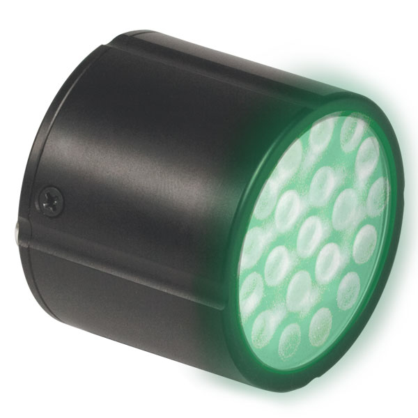
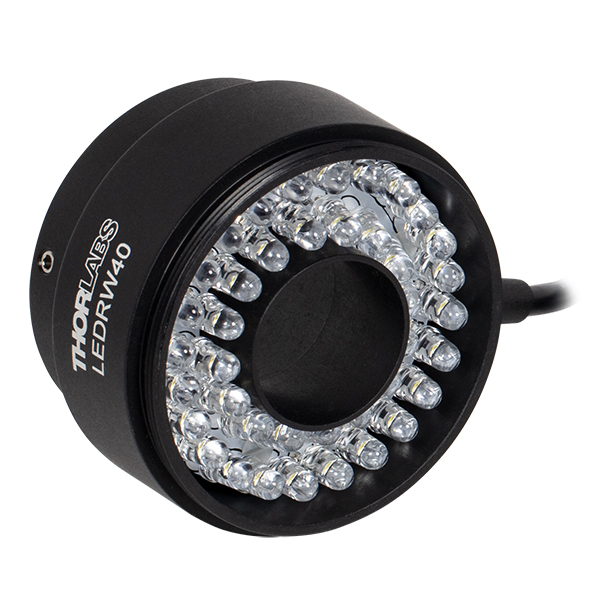
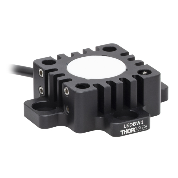
LED Arrays | LED Ring Light | Cage-Compatible Diffuse Backlight LED |
| Light Emitting Diode (LED) Selection Guide | ||||||
|---|---|---|---|---|---|---|
| Click Photo to Enlarge (Representative; Not to Scale) |
 |
 |
 |
 |
 |
 |
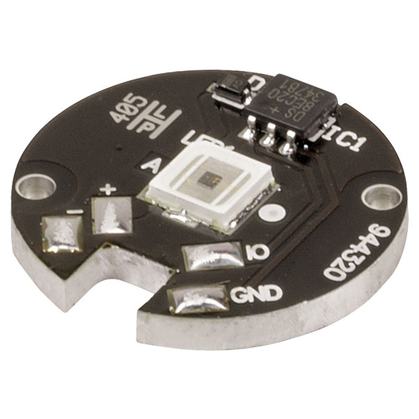
| Type | PCB- Mounted LEDs |
Heatsink- Mounted LEDs |
Collimated LEDs for Microscopyb | Fiber- Coupled LEDsc |
High-Power LEDs for Microscopy | Multi-Wavelength LED Source Optionsd |
| Item # | Wavelengtha,b | Optical Powera,c |
Spectral FWHMa |
Viewing Half Anglea |
Max DC Forward Currentd |
Package |
|---|---|---|---|---|---|---|
| LED255W | 255 nm | 0.4 mW | 11 nm | 60° | 30 mA | TO-39 |
| LED260W | 265 nm | 1 mW | 11 nm | 60° | 30 mA | Ø9 mm |
| LED275W | 275 nm | 1.6 mW | 11 nm | 60° | 30 mA | Ø9 mm |
| LED285J | 285 nme | 1.3 mWd | 11 nmc,d | 6°c,d | 30 mAd | TO-39 |
| LED290W | 290 nm | 1.6 mW | 11 nm | 60° | 30 mA | Ø9 mm |
| LED295W | 295 nm | 1.2 mW | 11 nm | 60° | 30 mA | TO-39 |
| LED310W | 310 nmf | 1.5 mW | 15 nm | 57° | 40 mA | TO-39 |
| LED325W2 | 325 nmf | 1.7 mW | 11 nm | 57° | 40 mA | TO-39 |
| LED340W | 340 nmf | 1.7 mW | 9 nm | 57° | 40 mA | TO-39 |
| LED341W | 340 nm | 0.33 mW | 15 nm | 60° | 20 mA | TO-39 |
| LED375L | 375 nmf | 1 mW | 10 nm | 20° | 30 mA | TO-18 |
| LED370E | 375 nm | 2.5 mW | 10 nm | 19° | 30 mA | T-1 3/4 |
| LED385L | 385 nmf | 5 mW | 12 nm | 16° | 30 mA | TO-18 |
| LED395L | 395 nmf | 6 mW | 15 nm | 16° | 30 mA | TO-18 |
| LED405L | 405 nmf | 6 mW | 20 nm | 17° | 30 mA | TO-18 |
| LED405E | 405 nm | 10 mW | 15 nm | 5° | 30 mA | T-1 3/4 |
| Item # | Wavelengtha,b | Optical Powera |
Spectral FWHMa |
Viewing Half Anglea |
Max DC Forward Currentc |
Package |
|---|---|---|---|---|---|---|
| LED430L | 430 nm | 8 mW (at 20 mA) | 20 nm | 22° | 50 mA | TO-18 |
| LED450L | 450 nm | 7 mW (at 20 mA) | 20 nm | 20° | 50 mA | TO-18 |
| LED450LW | 450 nm | 90 mW (at 100 mA) | 16 nm | 50° | 150 mA | TO-39 |
| LED465E | 465 nmd | 20.0 mW (at 20 mA) | 25 nm | 8° | 50 mA | T-1 3/4 |
| LED470L | 470 nm | 170 mW (at 350 mA) | 22 nm | 7º | 350 mA | TO-39 |
| LED490L | 490 nm | 3 mW (at 20 mA) | 20 nm | 20° | 50 mA | TO-18 |
| LED505L | 505 nm | 4 mW (at 50 mA) | 30 nm | 20° | 30 mA | TO-18 |
| LED525E | 525 nmd | 2.6 mW (at 20 mA) | 32 nm | 7.5° | 30 mA | T-1 3/4 |
| LED525L | 525 nm | 4 mW (at 50 mA) | 25 nm | 20° | 30 mA | TO-18 |
| LED528EHP | 525 nmd | 7.0 mW (at 20 mA) | 35 nm | 9° | 50 mA | T-1 3/4 |
| LED545L | 545 nm | 2.4 mW (at 20 mA) 8.7 mW (Pulsed, at 100 mA) |
39 nm | 12° | 50 mA | TO-18 |
| LED560L | 562 nmc | 0.15 mW (at 20 mA)c 0.6 mW (Max, at 50 mA)c |
11 nmc | 6°c | 50 mA | TO-18 |
| LED570L | 570 nm | 0.3 mW (at 20 mA) | 15 nm | 20° | 50 mA | TO-18 |
| LED590L | 590 nm | 2 mW (at 50 mA) | 15 nm | 20° | 30 mA | TO-18 |
| LED591E | 590 nmd | 2 mW (at 20 mA) | 20 nm | 10° | 50 mA | T-1 3/4 |
| LED595LW | 595 nm | 45 mW (at 100 mA) | 75 nm | 50° | 150 mA | TO-39 |
| LED600L | 600 nm | 3 mW (at 50 mA) | 12 nm | 15° | 75 mA | TO-18 |
| LED610L | 610 nm | 8 mW (at 50 mA) | 12 nm | 25° | 75 mA | TO-18 |
| LED625E | 625 nme | 9 mW (at 20 mA)c | 20 nmc,f | 10°c,f | 50 mA | T-1 3/4 |
| LED625L | 625 nm | 12 mW (at 50 mA) | 14 nm | 24° | 75 mA | TO-18 |
| LED630L | 630 nm | 16 mW (at 50 mA) | 14 nm | 22° | 75 mA | TO-18 |
| LED635L | 635 nmd | 170 mW (at 350 mA) | 15 nm | 7° | 500 mA | TO-39 |
| LED630E | 639 nmd | 7.2 mW (at 20 mA) | 17 nm | 7.5° | 50 mA | T-1 3/4 |
| LED645L | 645 nm | 16 mW (at 50 mA) | 16 nm | 20° | 75 mA | TO-18 |
| LED660L | 660 nm | 13 mW (at 50 mA) | 14 nm | 18° | 75 mA | TO-18 |
| LED670L | 670 nm | 12 mW (at 50 mA) | 22 nm | 22° | 75 mA | TO-18 |
| LED680L | 680 nm | 8 mW (at 50 mA) | 16 nm | 20° | 75 mA | TO-18 |
| Item # | Wavelengtha,b | Optical Powera |
Spectral FWHMa |
Viewing Half Anglea |
Max DC Forward Currentc |
Package |
|---|---|---|---|---|---|---|
| LED750L | 750 nm | 18 mW (at 50 mA) | 23 nm | 11° | 75 mA | TO-18 |
| LED760L | 760 nm | 24 mW (at 50 mA) | 24 nm | 12° | 75 mA | TO-18 |
| LED770L | 770 nm | 22 mW (at 50 mA) | 28 nm | 12° | 75 mA | TO-18 |
| LED780E | 780 nmd | 18 mW (at 50 mA) | 30 nm | 10° | 100 mA | T-1 3/4 |
| LED780L | 780 nm | 22 mW (at 50 mA) | 25 nm | 12° | 75 mA | TO-18 |
| LED800L | 800 nm | 20 mW (at 50 mA) | 30 nm | 12° | 75 mA | TO-18 |
| LED810L | 810 nm | 22 mW (at 50 mA) | 30 nm | 12° | 75 mA | TO-18 |
| LED830L | 830 nm | 22 mW (at 50 mA) | 32 nm | 12° | 75 mA | TO-18 |
| LED840L | 840 nm | 22 mW (at 50 mA) | 35 nm | 12° | 75 mA | TO-18 |
| LED850LN | 850 nm | 100 mW (at 500 mA) | 55 nm | 3.5° | 500 mA | TO-39 |
| LED850LW | 850 nm | 140 mW (at 500 mA) | 55 nm | 55° | 500 mA | TO-39 |
| LED851L | 850 nmd | 13 mW (at 20 mA) | 40 nm | 10° | 100 mA | TO-18 |
| LED870E | 870 nmd | 22 mW | 40 nm | 10° | 100 mA | T-1 3/4 |
| LED870L | 870 nm | 24 mW (at 50 mA) | 42 nm | 13° | 75 mA | TO-18 |
| LED890L | 890 nm | 12 mW (at 50 mA) | 44 nm | 14° | 75 mA | TO-18 |
| LED910L | 910 nm | 10 mW (at 50 mA) | 44 nm | 12° | 75 mA | TO-18 |
| LED910E | 910 nmd | 12 mW (at 50 mA) | 35 nm | 7° | 100 mA | Ø5.5 mm |
| LED930L | 930 nm | 15 mW (at 50 mA) | 60 nm | 14° | 75 mA | TO-18 |
| LED940E | 940 nmd | 18 mW | 50 nm | 10° | 100 mA | T-1 3/4 |
| LED970L | 970 nm | 5 mW (at 50 mA) | 46 nm | 14° | 75 mA | TO-18 |
| LED1050E | 1050 nmd | 2.5 mW | 55 nm | 15° | 100 mA | T-1 3/4 |
| LED1050L | 1050 nm | 4 mW (at 50 mA) | 50 nm | 15° | 100 mA | TO-18 |
| LED1050L2 | 1050 nmc | 8 mW (at 50 mA)c | 42 nmc | 9°c | 100 mAc | TO-46 |
| LED1070L | 1070 nm | 4 mW (at 50 mA) | 55 nm | 15° | 100 mA | TO-18 |
| LED1070E | 1070 nmd | 7.5 mW (at 50 mA) | 80 nm | 15° | 100 mA | T-1 3/4 |
| LED1085L | 1085 nm | 5 mW (at 50 mA) | 50 nm | 15° | 100 mA | TO-18 |
| LED1200E | 1200 nmd | 2.5 mW (at 20 mA) | 100 nm | 15° | 100 mA | T-1 3/4 |
| LED1200L | 1200 nm | 5 mW (at 50 mA) | 70 nm | 15° | 100 mA | TO-18 |
| LED1300E | 1300 nmd | 2 mW (at 20 mA) | 100 nm | 15° | 100 mA | T-1 3/4 |
| LED1300L | 1300 nm | 3.5 mW (at 50 mA) | 85 nm | 20° | 100 mA | TO-18 |
| LED1450E | 1450 nmd | 2 mW (at 20 mA) | 100 nm | 15° | 100 mA | T-1 3/4 |
| LED1450L | 1450 nm | 5 mW (at 50 mA) | 105 nm | 14° | 100 mA | TO-18 |
| LED1550E | 1550 nmd | 2 mW (at 20 mA) | 100 nm | 15° | 100 mA | T-1 3/4 |
| LED1550L | 1550 nm | 4 mW (at 50 mA) | 120 nm | 15° | 100 mA | TO-18 |
| LED1600L | 1600 nm | 2 mW (at 50 mA) | 130 nm | 15° | 100 mA | TO-18 |
| Item # | Center Wavelengtha,b |
Optical Powera,b |
Spectral FWHMa,b |
Viewing Half Anglea |
Max Quasi-CW (qCW) Forward Currenta |
Package |
|---|---|---|---|---|---|---|
| LED1600P | 1650 nm | 1.2 mW qCW at 200 mA | 150 nm | -c | 200 mA | TO-18R |
| LED2800W | 2830 - 2900 nmd,e,f | 300 µW qCW at 200 mAe (2000 µW Pulsed at 1 A)g |
300 nm (Min)e,f 500 nm (Max)e,f |
15° | 200 mAe,h | TO-18 |
| LED4400P | 4400 nmd | 12 µW qCW at 200 mA | 800 nm (Min) 1200 nm (Max) |
5°i | 250 mA | TO-18R |
| Item # | Center Wavelengtha |
Optical Powera |
Spectral FWHMa |
Viewing Half Anglea |
Max DC Forward Currentb |
Package |
|---|---|---|---|---|---|---|
| LEDGR | 625 nm and 572 nm | 0.19 mW and 0.09 mW (at 20 mA) | 40 nm and 30 nm | 15° | 30 mA | T-1 3/4c |
| LEDRY | 617 nm and 588 nm | 0.19 mW and 0.09 mW (at 20 mA) | 45 nm and 35 nm | 30° | 30 mA | T-1 3/4c |
| LEDRGBE (R, G, and B) |
627.5 nm, 525 nm, and 467.5 nm |
5.8 mW, 3.1 mW, and 6.2 mW | 20 nm, 36 nm, and 15 nm |
25° | 50 mA | T-1 3/4c |

 Zoom
Zoom| Item # | LEDMT1E | LEDMT1F |
|---|---|---|
| Input Voltage (VI) | 5 V | |
| Resistance | 51 Ω | 62 Ω |
| Compatible LED Package | T-1 3/4a | |
| Mounting Thread | External SM05 (0.535"-40) | |
| Outer Dimensions | Ø0.70" x 0.83" | |
| Compatible LEDsb | LED370E LED405E LED465E LED528EHP LED780E LED870E LED940E LED1050E LED1070E LED1200E LED1300E LED1450E LED1550E |
LED525E LED591E LED625E LED630E LEDW25E LEDW7E |
Click for Details
LEDMT1E Mechanical Schematic
Click to Enlarge
LEDMT1E Electrical Schematic
- USB-Powered Mount for LEDs in T-1 3/4 Packages
- Options with Built-In 51 Ω or 62 Ω Current-Limiting Resistor for Different Electrical Requirements
- External SM05 (0.535"-40) Mounting Thread
- Includes Micro-B USB to USB Type-A Cable for Power LED Module
These USB-Powered LED Mounts provide both power and a mounting socket for our unmounted LEDs in T-1 3/4 packages within a single compact housing. Because of the varied electrical requirements, we offer the LED mounts with either a 51 Ω or 62 Ω current-limiting resistor. The module is powered via the micro-B USB port on the back of the housing which can be connected to a USB power source or PC via the included USB to micro-B USB cable. The housing exterior features external SM05 (0.535"-40) threading which can be used to integrate these mounts with a cage system or SM05-threaded component.
When mounting an LED, use the engraving on the housing to determine the appropriate length to cut the leads (see drawing to the right). Insert the LED with the anode lead going into the socket indicated by a (+) sign and the cathode into the socket indicated by a (-) sign. Use light force to mount the LED as excessive force may bend the electrode leads.
These powered mounts offer a fixed resistance and input voltage; choosing the appropriate mount for your LED will minimize damage to the LED. In general, a mount with a lower resistance value will increase the forward current available to the LED and proportionally increase the optical output power. However, the forward current must not exceed the maximum current of LED as this can cause permanent damage to the LED. The minimum mount resistance (R) recommended to use a desired LED is given by the following equation:

where the input voltage of the mount (VI,Source) is 5 V and the typical forward voltage (VF,Typ) and maximum forward current (IF,Max) are properties of each LED. Please consult the specifications of your LED for these values.

 Zoom
Zoom| LED Mount Compatibility | ||||
|---|---|---|---|---|
| Item # | LED Package | External Mounting Threads |
Compatible Spanner Wrenches |
|
| Mount | LED Retaining Ring |
|||
| LEDMF | TO-18, TO-18R, and T-1 3/4a |
Smooth Bore | N/A | N/A |
| S05LEDM | TO-18, TO-39, TO-46, and T-1 3/4a |
SM05 (0.535"-40) |
SPW603 SPW801 |
SPW301 SPW801 |
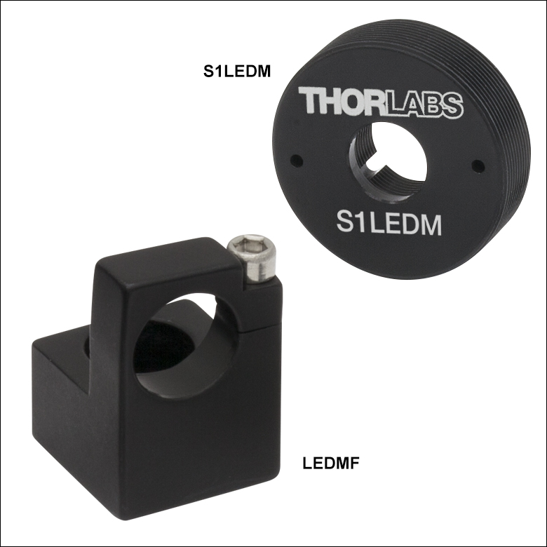
| S1LEDM | SM1 (1.035"-40) |
SPW909 SPW801 |
||
The LEDMF LED Mount is designed to hold any of Thorlabs' TO-18R packages directly or our T-1 3/4 or TO-18 packages using one of the included adapter rings (Ø4.7 mm adapter for TO-18 or Ø5 mm adapter for T-1 3/4). The LED is secured in the mount with a top-located cap screw with a 5/64" (2 mm) hex. The L-shaped mount has a counterbored through hole suitable for an 8-32 (M4) cap screw so that the LEDMF can be attached to a Ø1/2" Post.
The S05LEDM and S1LEDM LED Mounts are SM05 (0.535"-40) and SM1 (1.035"-40) threaded, respectively. They are designed to hold any of Thorlabs' TO-18, TO-39, TO-46, or T-1 3/4 packages using the included adapter rings. The external threading on these mounts allows them to be used in a wide variety of SM05- or SM1-compatible optomechanics.
To aid in threading the retaining ring into the mount or in threading the mount into a mating component, we recommend using our selection of spanner wrenches. The SPW801 Adjustable Spanner Wrench can be used to thread LED retaining rings into the mount and the mount into a mating component. Alternatively, the table to the right also lists the compatible fixed spanner wrench for each mount.

 Zoom
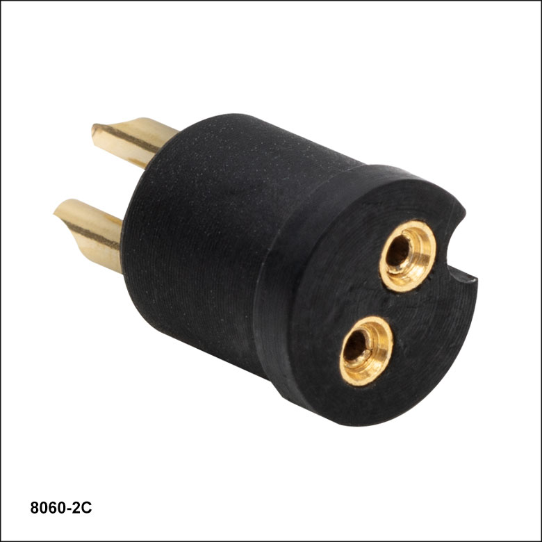
Zoom| Specifications | |
|---|---|
| Conductor | Beryllium Copper (BeCu) |
| Insulator | PTFE |
| Compatible Lead Diameters | 0.015" - 0.025" (0.38 mm - 0.64 mm) |
| Compatible Lead Lengths | ≤0.15" (3.8 mm) |
| Outer Diameter | 0.25" (6.4 mm) |
| Substrate Thickness | 0.27" (6.9 mm) |
Click to Enlarge
8060-2C Socket Schematic
Thorlabs offers a light-emitting diode (LED) socket that is compatible with LEDs that have two leads. This socket fits LED leads that are Ø0.015" - Ø0.025"(Ø0.38 - Ø0.64 mm) and ≤0.15" (3.8 mm) long. The socket has gold-plated beryllium copper contacts and meets RoHS compliance. Color varies by lot and may be white, off white, black, or tan.