 Products Home / Optical Elements / Optical Filters / Kurios® Liquid Crystal Tunable Bandpass Filters
Kurios® Liquid Crystal Tunable Bandpass Filters

- Tunable Bandpass Filters for Visible and NIR Wavelengths
- Ideal for Multispectral and Hyperspectral Imaging
- Available with Fixed or Selectable Bandwidth
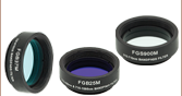
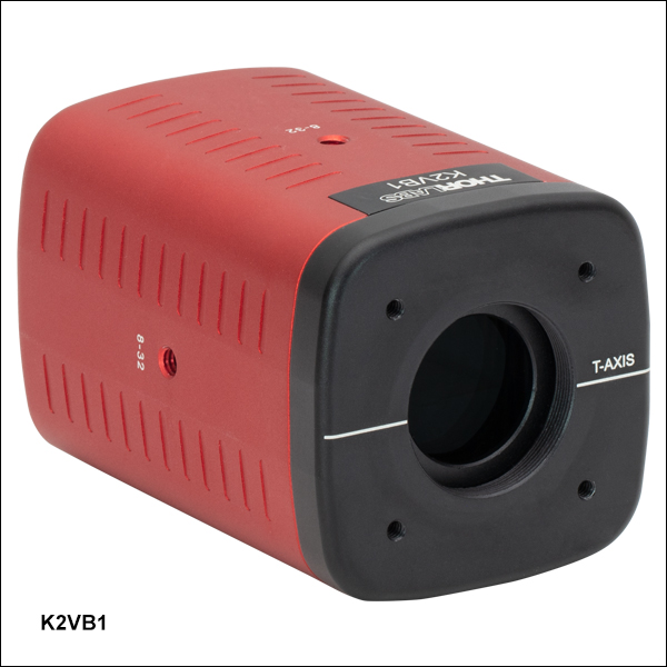
K2VB1
Variable Bandwidth, Ø20 mm CA
Application Idea
The Kurios® filter heads can be connected to 30 mm cage systems for custom optical assemblies.
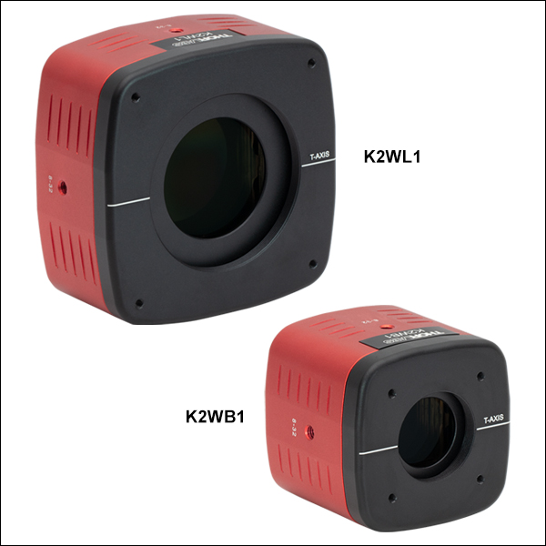
K2WL1
Fixed Bandwidth, Ø35 mm CA
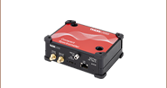
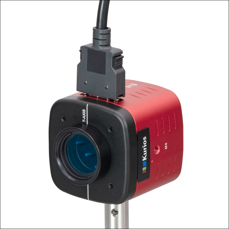
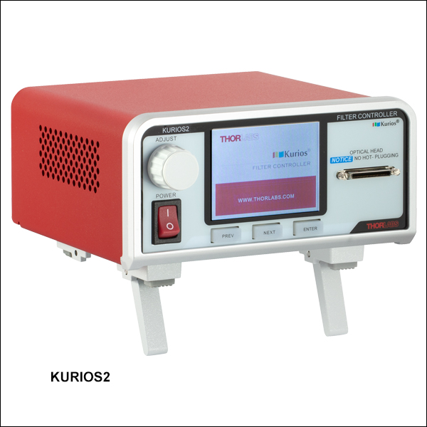
KURIOS2
Controller for Kurios® Filters


Please Wait
Click to Enlarge
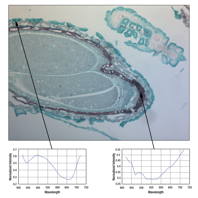
Figure 1.1 A hyperspectral image of a root cell taken using the previous-generation KURIOS-WB1. Two sample spectrums at the regions indicated are also shown. More details on this measurement are available in the Application Ideas tab.
Features
- Tunable Optical Filters with Fully Programmable Sequences
- Temperature-Controlled Head for Long-Term Stability
- Ø20 mm or Ø35 mm Clear Aperture
- Requires KURIOS2 Controller (Sold Separately Below)
- Provides Local Control via the Front Panel and Remote Control via BNC and USB
- Software and SDK Included (See Software Tab for Details)
- Several Mounting Options
- Three 8-32 (M4 x 0.7) Tapped Holes for Post Mounting
- Internal SM1 (1.035"-40) or SM2 (2.035"-40) Threads on Both Sides
- 4-40 Tapped Holes on Both Sides for 30 mm or 60 mm Cage Systems
- Filters are Factory Calibrated and Include a Test Report (Click Here for a Sample Test Report)
Kurios® Liquid Crystal Tunable Bandpass Filters provide a continuously tunable center wavelength (CWL) in the 420 - 730 nm, 430 - 730 nm, or 650 - 1100 nm range. Most Kurios models have a fixed bandwidth for any given center wavelength. Alternatively, the K2VB1(/M) has user-selectable bandwidth settings of Narrow, Medium, and Wide. The switching time varies depending upon the initial and final wavelengths and on the Kurios' bandwidth setting (for K2VB1(/M) only). See the plots in Tables G1.1 through G4.1 for details.
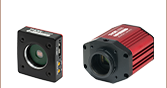
The Kurios optical filters require the KURIOS2 controller for operation (sold separately below). It provides Trigger In, Trigger Out, and Analog In functionality, making these tunable optical bandpass filters ideal for applications that perform multispectral or hyperspectral imaging, as demonstrated in Figure 1.1. For example, they can be used in conjunction with a monochrome scientific CMOS camera to obtain images with a much higher accuracy for color representation than using a color CMOS camera with a Bayer mosaic. This technique produces true spectral imaging and can thus show spectral features that would otherwise be impossible to detect. Thorlabs' Kurios tunable filters and CMOS cameras are also compatible with our modular Cerna® Microscopy Platform that supports customizable microscopy solutions. For examples of how the Kurios filters can be integrated with the Cerna microscopy platform and standard optomechanical components, please see the Application Ideas tab.
Similar in construction to Lyot and Solc filters, Kurios filters consist primarily of liquid crystal cells that are sandwiched between polarizing elements. Their integrated design enables quick and vibrationless tuning. For added operational stability, a closed-loop temperature control servo is used to maintain the filter head's operating temperature. An LED on the filter head displays red when the head is warming up and green when it is ready to be used.

Click to Enlarge
Figure 1.2 The back of the filter head contains the same mounting features as the front. The output polarization is rotated by 90° with respect to the input polarization.

Click to Enlarge
Figure 1.3 The front of the filter head contains internal SM1 or SM2 threads, four
Wavelength Control with KURIOS2 Controller
The controller's front panel provides manual control of the center wavelength and enables programmable switching sequences, as described in the Control tab. It also features three menu buttons that can be used to toggle through various operating modes. For the K2VB1(/M), the buttons toggle between Narrow, Medium, and Wide (the three selectable bandwidths), as well as beam-blocking mode ("Black"). For the fixed bandwidth models, the buttons toggle between the only bandwidth available and Black mode. Please see the Control tab for more details.
The KURIOS2 controller also offers three BNC connectors (Trigger In, Trigger Out, and Analog In) that allow a Kurios filter to be synchronized with a wide range of other devices, such as scientific cameras and motion control stages. Each Kurios filter is factory calibrated and ships with a switching time map so that the user may optimize their system for the specific filter.
Click to Enlarge
Figure 1.4 The K2WB1/M Filter Head With the Included FESH0750 Hard-Coated Shortpass Filter
Transmission and Polarization
The liquid crystal optics in Kurios filters are not sensitive to the direction of propagation, allowing the filter to be used in either direction. The first element in the filter head is a linear polarizer and each face is marked with a white line (see Figures 1.2 and 1.3) that indicates the transmitted polarization direction. For maximum transmission, the input beam should be linearly polarized and aligned with this polarization axis. Please note that since Kurios filters are structured like Lyot and Solc filters, the polarization axis rotates by 90° through the filter head. To obtain the specified attenuation of out-of-band wavelengths, the input beam should be well collimated, since the filter head's field of view is ±6°.
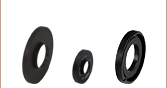
A lens-tube-mounted hard-coated 750 nm shortpass filter is included with our K2WB1(/M), K2WL1(/M), K2XE1(/M), K2XL1(/M), and K2VB1(/M) Tunable Filters for visible wavelengths. Use of this filter is recommended to protect the filter head components from excessive IR illumination.
Mounting Options
These tunable filters are post mountable via three 8-32 (M4 x 0.7) taps on the sides of the housing. In addition, four 4-40 tapped holes on the front and back faces provide compatibility with our 30 mm or 60 mm cage systems, depending on the model. The front and back faces of the housing are internally SM1- (1.035"-40) or SM2- (2.035"-40) threaded. These threads accommodate Ø1" or Ø2" lens tubes, respectively. To connect the K2WB1(/M) or K2VB1(/M) filter to a camera, use our SM1A39 SM1-to-C-Mount thread adapter together with an appropriate tube lens.
| Fixed Bandwidth Tunable Filters | ||||||
|---|---|---|---|---|---|---|
| Item # | K2WB1(/M) | K2WL1(/M) | K2XE1(/M) | K2XL1(/M) | K2XE2(/M) | |
| Wavelength Range | 420 - 730 nm | 430 - 730 nm | 650 - 1100 nm | |||
| Bandwidth (FWHM)a | 35 nm at 550 nm | 10 nm at 550 nm | 17 nm at 850 nm | |||
| Switching Speedb | <150 ms | <250 ms | <760 ms | |||
| Clear Aperture | Ø20 mm | Ø35 mm | Ø20 mm | Ø35 mm | Ø20 mm | |
| Polarized Transmissionc | 45% at 550 nm | 17% at 550 nm | 44% at 850 nm | |||
| Out-of-Band Blocking | OD > 2 | |||||
| Minimum Incremental Step Size | 1 nm | |||||
| Tuning Accuracy | ±FWHM/10 | |||||
| Field of View | ±6° | |||||
| Wavelength Uniformity | FWHM/8 | FWHM/4 | ||||
| Damage Threshold | Pulsed (ns) | 0.1 J/cm2 | 0.1 J/cm2 (810 nm, 10 Hz, 7.2 ns, Ø216 µm) | |||
| Pulsed (fs) | 0.02 J/cm2 (532 nm, 76 Hz, 100 fs, Ø162 µm) | 0.006 J/cm2 (800 nm, 100 Hz, 36.4 fs, Ø189 µm) | ||||
| CW | 0.8 W/cmd (532 nm, Ø0.471 mm) | - | ||||
| Filter Head Dimensions | 52.6 mm x 52.6 mm x 48.5 mm (2.07" x 2.07" x 1.91") |
79.0 mm x 79.0 mm x 39.5 mm (3.11" x 3.11" x 1.56") |
52.6 mm x 52.6 mm x 78.5 mm (2.07" x 2.07" x 3.09") |
79.0 mm x 79.0 mm x 60.5 mm (3.11" x 3.11" x 2.38") |
52.6 mm x 52.6 mm x 87.5 mm (2.07" x 2.07" x 3.44") |
|
| Filter Head Front/Rear Threading | SM1 (1.035"-40) Internal Threads | SM2 (2.035"-40) Internal Threads | SM1 (1.035"-40) Internal Threads | SM2 (2.035"-40) Internal Threads | SM1 (1.035"-40) Internal Threads | |
| Filter Head Mounting Options | 8-32 (M4 x 0.7) Tap for Post Mounting (3 Places) 4-40 Taps for Cage System |
|||||
| Operating Temperature | 15 to 40 °C | |||||
| Storage Temperature | -15 to 65 °C | |||||
| KURIOS2 Controller | |
|---|---|
| Electrical Characteristics | |
| Adjustable Output Voltage | 0 to ±25 V RMS |
| Voltage Resolution | 1.0 mV |
| Switching Frequency | 2000 ± 1 Hz, 50% Duty Cycle |
| Slew Rate | 10 V/μs |
| DC Offset | ±5 mV |
| Warm-Up Time | 30 min |
| USB Port | USB Standrad B Plug |
| Power Compatibility | 110 - 240 VAC, 50 - 60 Hz Operation, Location Specific Power Cord Included |
| Maximum Ratings | |
| Maximum External Input Voltage | 5 VDC |
| Maximum Output Current | 50 mA |
| Maximum Heating Current | 900 mA |
| Operating Temperature Range | 10 to 40 °C |
| Maximum Relative Humidity | 85% |
| General Specifications | |
| Dimensions (L x W x H) | 177.0 mm x 154.0 mm x 85.0 mm (6.97" x 6.03" x 3.35") |
| Weight | 0.89 kg |
| Selectable Bandwidth Tunable Filter | ||
|---|---|---|
| Item # | K2VB1(/M) | |
| Wavelength Range | 420 - 730 nm | |
| Bandwidth, CWL = 550 nma | Narrow: 10 nm FWHM Medium: 18 nm FWHM Wide: 32 nm FWHM |
|
| Switching Speedb | Narrow: <750 ms Medium: <500 ms Wide: <250 ms |
|
| Clear Aperture | Ø20 mm | |
| Polarized Transmission, CWL = 550 nmc |
Narrow: 13% Medium: 17% Wide: 20% |
|
| Out-of-Band Blocking | OD > 2 | |
| Minimum Incremental Step Size | 1 nm | |
| Tuning Accuracy | ±FWHM/10 | |
| Angle of Incidence (Field of View) | ±6° | |
| Wavelength Uniformity | FWHM/4 | |
| Damage Threshold | Pulsed (ns) | 0.1 J/cm2 |
| Pulsed (fs) | 0.02 J/cm2 (532 nm, 76 Hz, 100 fs, Ø162 µm) | |
| CW | 0.8 W/cmd (532 nm, Ø0.471 mm) | |
| Filter Head Dimensions | 52.6 mm x 52.6 mm x 78.5 mm (2.07" x 2.07" x 3.09") |
|
| Filter Head Front/Rear Threading | SM1 (1.035"-40) Internal Threads | |
| Filter Head Mounting Options | 8-32 (M4 x 0.7) Tap for Post Mounting (3 Places) 4-40 Taps for Cage System |
|
| Operating Temperature | 15 to 40 °C | |
| Storage Temperature | -15 to 65 °C | |
Kurios® tunable bandpass filters have three operating modes for control of the center wavelength: Manual, Sequenced, and Analog. They also provide a beam blocking mode ("black mode"). Full details on the operation are available in the KURIOS2 controller manual.

Click to Enlarge
Figure 3.1 The front panel of the KURIOS2 controller.
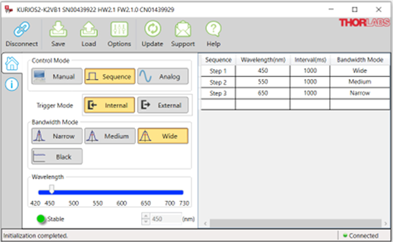
Click to Enlarge
Figure 3.2 The main window of the software when the K2VB1 Selectable Bandpass Tunable Filter is connected. (When using the K2WB1(/M) or K2WL1(/M) filters, the Narrow and Medium buttons are grayed out. For the K2XE1(/M), K2XE2(/M), or K2XL1(/M) filters, the Medium and Wide buttons are grayed out.)
Manual Mode
In manual mode, the center wavelength is immediately set when a command is issued. This command can be issued in several ways:
- Turn the ADJUST knob on the KURIOS2 front panel (see Figure 3.1).
- Use the PREV, NEXT, and ENTER buttons on the KURIOS2 front panel to toggle "WAVELENGTH", and change the value using either the ADJUST knob or the PREV and NEXT buttons.
- Use the wavelength slider in the software interface (shown in Figure 3.2).
- Type the desired wavelength into the software interface.
- Issue the serial command.
The KURIOS2 controller defaults to the manual mode when it is powered on. If the controller is not in manual mode, it can be activated through any of the following methods:
- Use the PREV, NEXT, and ENTER buttons on the KURIOS2 controller's front panel to toggle "MODE", and change the selection to "MANUAL".
- Press Manual in the software interface (shown in Figure 3.2).
- Issue the serial command.
Bandwidth (Item # K2VB1(/M) Only)
For the K2VB1(/M) Selectable Bandpass Tunable Filter, the bandwidth (Narrow, Medium, or Wide) can be set using any of the following methods:
- Use the PREV, NEXT, and ENTER buttons on the KURIOS2 front panel to toggle "BANDWIDTH", and change the selection to either "NARROW", "MEDIUM", or "WIDE".
- Press Narrow, Medium, or Wide in the software interface (shown in Figure 3.2).
- Issue the proper serial commands.
Sequenced Mode
In sequenced mode, the KURIOS2 controller stores a series of center wavelengths that it sends to the optical head whenever an internal or external trigger is received. The maximum number of wavelengths that can be stored in the sequence is 1024; at the end of the sequence, the controller loops back to the beginning and starts over again. This sequence is stored within the controller's non-volatile memory, enabling the user to close the software GUI or unplug with USB cable without loss of the preloaded sequence. However, powering off the controller will cause the non-volatile memory to reset. The software is used to input the sequence of wavelengths desired. Sequenced mode can be activated using any of the following methods:
- Use the PREV, NEXT, and ENTER buttons on the KURIOS2 front panel to toggle "MODE" and change the selection to either "SEQ.INT" or "SEQ.EXT".
- Press Sequence in the software interface (shown in Figure 3.2).
- Issue the proper serial commands.
Analog Mode
In analog mode, the center wavelength is directly controlled by a 0 to 5 V signal connected to the ANALOG IN connector on the KURIOS2 controller's back panel. A signal of 0 V corresponds to the shortest wavelength and 5 V to the longest. When an internal or external trigger is received, the center wavelength is updated to the value determined by the ANALOG IN voltage; at all other times, the ANALOG IN voltage is ignored. Analog mode can be accessed using any of the following methods:
- Use the PREV, NEXT, and ENTER buttons on the KURIOS2 front panel to toggle "MODE" and change the selection to either "ANA.INT" or "ANA.EXT".
- Press Analog in the software interface (shown in Figure 3.2).
- Issue the proper serial commands.
Internal and External Triggering
In both sequenced and analog modes, an internal or external trigger is needed to update the center wavelength. Otherwise, the wavelength remains unchanged.
For internal triggering, the signal is provided by a clock within the controller and has a user-specified interval between triggers from 1 ms to 60 s. Moreover, when in sequenced mode, each wavelength in the sequence can have its own interval time. In contrast, when in analog mode, the controller updates the wavelength according to the analog input signal at the interval time set by the user.
For external triggering, the 5 V TTL signal is provided through the Trigger In BNC connector on the back panel. The user can choose whether the trigger occurs on the rising or falling edge of the signal.
Beam Blocking Mode
In beam blocking mode ("black mode"), the transmission is set to a minimum value, ignoring the center wavelength setting. This mode can be activated through any of the following methods:
- Use the PREV, NEXT, and ENTER buttons on the KURIOS2 front panel to toggle "BANDWIDTH" and change the selection to "BLACK".
- Press Black in the software interface (shown in Figure 3.2).
- Issue the proper serial command.
Click to Enlarge
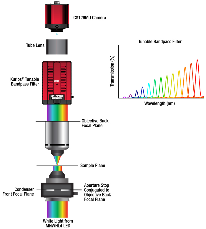
Figure 4.2 Schematic of the Hyperspectral Imaging Microscope
Click for Details
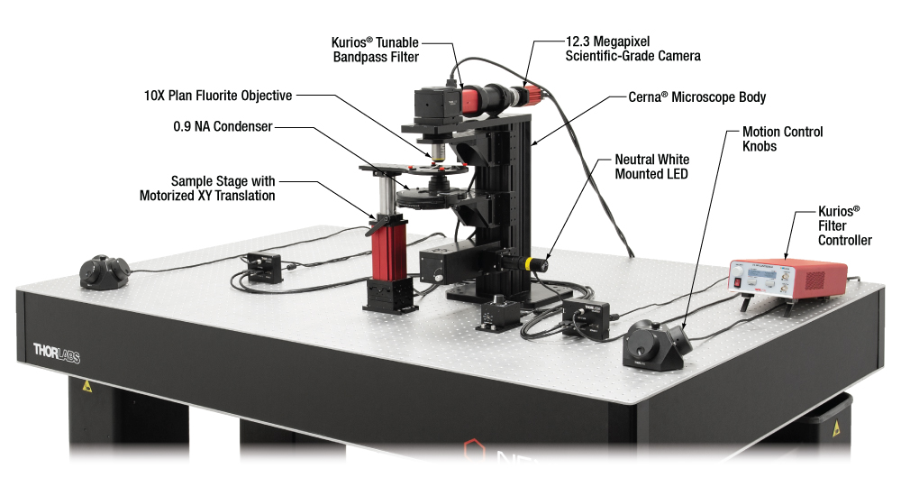
Figure 4.1 This DIY hyperspectral imaging system is built on Thorlabs' Cerna Microscopy Platform. Key components include the previous-generation KURIOS-VB1 Tunable Bandpass Filter, the CS126MU Monochrome Scientific Camera, and our MNWHL4 Neutral White Mounted LED.
Hyperspectral Imaging
In hyperspectral imaging, a stack of wavelength-separated, two-dimensional images is acquired. This technique is frequently used in microscopy, biomedical imaging, and machine vision, as it allows quick sample identification and analysis.
Hyperspectral imaging obtains images with significantly better spectral resolution than that provided by standalone color cameras. Color cameras represent the entire spectral range of an image by using three relatively wide spectral channels-red, green, and blue. In contrast, hyperspectral imaging systems incorporate optical elements such as liquid crystal tunable bandpass filters or diffraction gratings, which create spectral channels with significantly narrower bandwidths.
Example Image Stacks
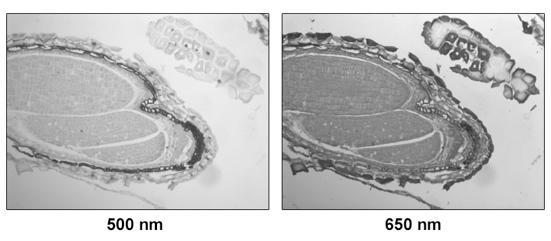
The data in Figures 4.3 and 4.5 and Video 4.4 demonstrate the hyperspectral imaging technique. Figure 4.3 depicts two images of a mature capsella bursa-pastoris embryo (also known as shepherd's-purse) taken with the tunable filter set to center wavelengths of 500 nm and 650 nm. These two images show that an entire field of view is acquired at each spectral channel. Video 4.4 is a video containing 31 images of the same sample, taken at center wavelengths from 420 nm to 730 nm in 10 nm steps. (10 nm is not the spectral resolution; the spectral resolution is set by the FWHM bandwidth at each wavelength.) In Figure 4.5, images from each spectral channel are used to determine the color of each pixel and assemble a color image. Figure 4.5 also demonstrates that a broadband spectrum is acquired at each pixel, permitting spectroscopic identification of different sample features within the field of view.
Kurios® tunable filters offer a number of advantages for hyperspectral imaging. Unlike approaches that rely upon angle-tunable filters or manual filter swapping, Kurios filters use no moving parts, enabling vibrationless wavelength switching on millisecond timescales. Because the filter is not moved or exchanged during the measurement, the data is not subject to "pixel shift" image registration issues. Our filters also include software and a benchtop controller with external triggers, making them easy to integrate with data acquisition and analysis programs.
Click to Enlarge
Figure 4.5 A color image of the mature capsella bursa-pastoris embryo, assembled using the entire field of view acquired in each spectral channel, as shown in Figure 1. By acquiring across multiple channels, a spectrum for each pixel in the image is obtained.
Click to Enlarge
Figure 4.3 Two images of a mature capsella bursa-pastoris embryo taken at different center wavelengths. The entire field of view is acquired for each spectral channel.
Video 4.4 This video shows the image obtained from the sample as a function of the center wavelength of the previous-generation KURIOS-WB1 tunable filter. The center wavelength was incremented in 10 nm steps from 420 nm to 730 nm. (10 nm is not the spectral resolution; the spectral resolution is set by the FWHM bandwidth at each wavelength.)
Tunable-Wavelength Illumination Sources
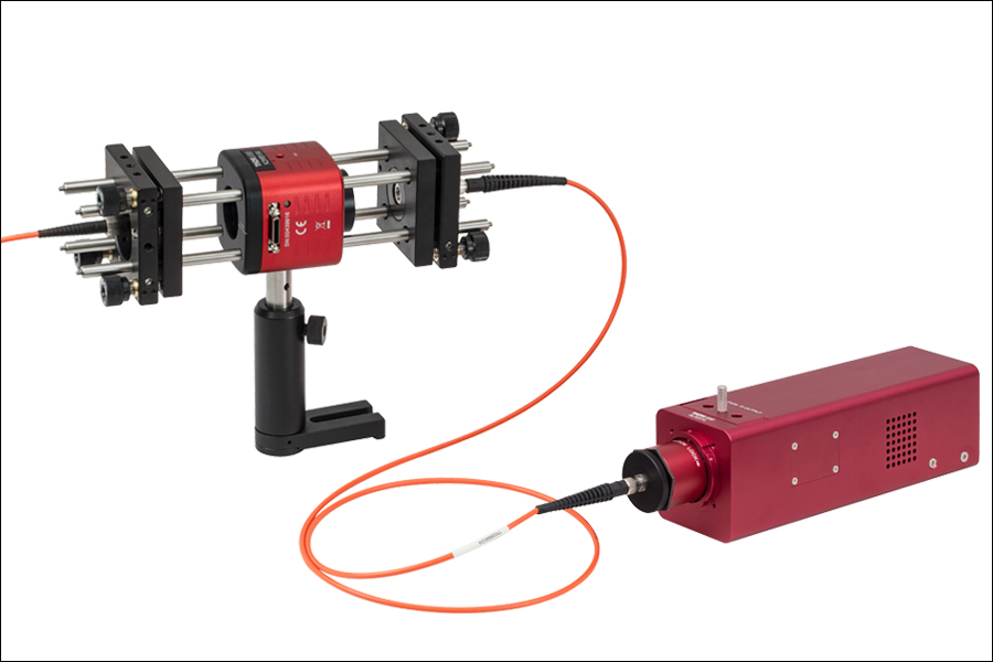
The system shown in Figure 4.6 uses a Kurios tunable filter and a broadband illumination source to provide millisecond-timescale tuning between visible wavelengths (420 - 730 nm).
Click to Enlarge
Figure 4.6 The K2WB1/M filter is connected to an SLS201L tungsten-halogen light source to create a tunable illumination source for visible wavelengths.
Click to Enlarge
Figure 5.1 The main window of the software when the K2VB1 Selectable Bandpass Tunable Filter is connected. (When using the K2WB1(/M) or K2WL1(/M), the Narrow and Medium buttons are grayed out. For the K2XL1(/M), the Medium and Wide buttons are grayed out.)
Software
Version 1.9.6
Includes a GUI for control of Kurios, as well as the required device drivers, C/C++ code examples, and LabVIEW VIs. To download, click this button.

Kurios® Software Package
GUI Interface
The Kurios software package allows the user to select between the Manual, Sequence, and Analog Modes for determining the center wavelength of the filter head. (These modes are discussed in detail in the Control tab.) In manual mode, the wavelength slider is enabled, which lets the user choose any center wavelength within the 420 - 730 nm, 430 - 730 nm, or 650 - 1100 nm range. For sequence and analog modes, either internal or external triggering can be chosen; triggers are needed to update the center wavelength.
In sequence and analog modes, the user may define sequences of up to 1024 wavelengths to be cycled through by the controller. Each step in the sequence has its own wavelength and duration (1 ms to 60 s), and for K2VB1(/M), the bandwidth can also be changed from step to step. Sequences can be saved and loaded in CSV format using the "Save Profile" and "Load Profile" buttons.
Custom Software Development
We also provide C/C++ and LabVIEW software development kits for controlling Kurios with other instruments through the USB port on the controller. Sample C++ code and LabVIEW programs help to illustrate how the C commands and LabVIEW VIs can be utilized.
| Table 6.1 Damage Threshold Specifications | ||
|---|---|---|
| Item # Suffix | Laser Type | Damage Threshold |
| -WB1(/M) -WL1(/M) -XE1(/M) -XL1(/M) -VB1(/M) |
Pulsed (ns) | 0.1 J/cm2 |
| Pulsed (fs) | 0.02 J/cm2 (532 nm, 76 Hz, 100 fs, Ø162 µm) | |
| CWa | 0.8 W/cm (532 nm, Ø0.471 mm) | |
| -XE2(/M) | Pulsed (ns) | 0.1 J/cm2 (810 nm, 10 Hz, 7.2 ns, Ø216 μm |
| Pulsed (fs) | 0.006 J/cm2 (800 nm, 100 Hz, 36.4 fs, Ø189 µm) | |
Damage Threshold Data for Kurios® Tunable Bandpass Filters
The specifications in Table 6.1 are measured data for Thorlabs' Kurios Tunable Filters.
Laser Induced Damage Threshold Tutorial
The following is a general overview of how laser induced damage thresholds are measured and how the values may be utilized in determining the appropriateness of an optic for a given application. When choosing optics, it is important to understand the Laser Induced Damage Threshold (LIDT) of the optics being used. The LIDT for an optic greatly depends on the type of laser you are using. Continuous wave (CW) lasers typically cause damage from thermal effects (absorption either in the coating or in the substrate). Pulsed lasers, on the other hand, often strip electrons from the lattice structure of an optic before causing thermal damage. Note that the guideline presented here assumes room temperature operation and optics in new condition (i.e., within scratch-dig spec, surface free of contamination, etc.). Because dust or other particles on the surface of an optic can cause damage at lower thresholds, we recommend keeping surfaces clean and free of debris. For more information on cleaning optics, please see our Optics Cleaning tutorial.
Testing Method
Thorlabs' LIDT testing is done in compliance with ISO/DIS 11254 and ISO 21254 specifications.
First, a low-power/energy beam is directed to the optic under test. The optic is exposed in 10 locations to this laser beam for 30 seconds (CW) or for a number of pulses (pulse repetition frequency specified). After exposure, the optic is examined by a microscope (~100X magnification) for any visible damage. The number of locations that are damaged at a particular power/energy level is recorded. Next, the power/energy is either increased or decreased and the optic is exposed at 10 new locations. This process is repeated until damage is observed. The damage threshold is then assigned to be the highest power/energy that the optic can withstand without causing damage. A histogram such as that shown in Figure 37B represents the testing of one BB1-E02 mirror.

Figure 37A This photograph shows a protected aluminum-coated mirror after LIDT testing. In this particular test, it handled 0.43 J/cm2 (1064 nm, 10 ns pulse, 10 Hz, Ø1.000 mm) before damage.

Figure 37B Example Exposure Histogram used to Determine the LIDT of
| Table 37C Example Test Data | |||
|---|---|---|---|
| Fluence | # of Tested Locations | Locations with Damage | Locations Without Damage |
| 1.50 J/cm2 | 10 | 0 | 10 |
| 1.75 J/cm2 | 10 | 0 | 10 |
| 2.00 J/cm2 | 10 | 0 | 10 |
| 2.25 J/cm2 | 10 | 1 | 9 |
| 3.00 J/cm2 | 10 | 1 | 9 |
| 5.00 J/cm2 | 10 | 9 | 1 |
According to the test, the damage threshold of the mirror was 2.00 J/cm2 (532 nm, 10 ns pulse, 10 Hz, Ø0.803 mm). Please keep in mind that these tests are performed on clean optics, as dirt and contamination can significantly lower the damage threshold of a component. While the test results are only representative of one coating run, Thorlabs specifies damage threshold values that account for coating variances.
Continuous Wave and Long-Pulse Lasers
When an optic is damaged by a continuous wave (CW) laser, it is usually due to the melting of the surface as a result of absorbing the laser's energy or damage to the optical coating (antireflection) [1]. Pulsed lasers with pulse lengths longer than 1 µs can be treated as CW lasers for LIDT discussions.
When pulse lengths are between 1 ns and 1 µs, laser-induced damage can occur either because of absorption or a dielectric breakdown (therefore, a user must check both CW and pulsed LIDT). Absorption is either due to an intrinsic property of the optic or due to surface irregularities; thus LIDT values are only valid for optics meeting or exceeding the surface quality specifications given by a manufacturer. While many optics can handle high power CW lasers, cemented (e.g., achromatic doublets) or highly absorptive (e.g., ND filters) optics tend to have lower CW damage thresholds. These lower thresholds are due to absorption or scattering in the cement or metal coating.

Figure 37D LIDT in linear power density vs. pulse length and spot size. For long pulses to CW, linear power density becomes a constant with spot size. This graph was obtained from [1].

Figure 37E Intensity Distribution of Uniform and Gaussian Beam Profiles
Pulsed lasers with high pulse repetition frequencies (PRF) may behave similarly to CW beams. Unfortunately, this is highly dependent on factors such as absorption and thermal diffusivity, so there is no reliable method for determining when a high PRF laser will damage an optic due to thermal effects. For beams with a high PRF both the average and peak powers must be compared to the equivalent CW power. Additionally, for highly transparent materials, there is little to no drop in the LIDT with increasing PRF.
In order to use the specified CW damage threshold of an optic, it is necessary to know the following:
- Wavelength of your laser
- Beam diameter of your beam (1/e2)
- Approximate intensity profile of your beam (e.g., Gaussian)
- Linear power density of your beam (total power divided by 1/e2 beam diameter)
Thorlabs expresses LIDT for CW lasers as a linear power density measured in W/cm. In this regime, the LIDT given as a linear power density can be applied to any beam diameter; one does not need to compute an adjusted LIDT to adjust for changes in spot size, as demonstrated in Figure 37D. Average linear power density can be calculated using this equation.

This calculation assumes a uniform beam intensity profile. You must now consider hotspots in the beam or other non-uniform intensity profiles and roughly calculate a maximum power density. For reference, a Gaussian beam typically has a maximum power density that is twice that of the uniform beam (see Figure 37E).
Now compare the maximum power density to that which is specified as the LIDT for the optic. If the optic was tested at a wavelength other than your operating wavelength, the damage threshold must be scaled appropriately. A good rule of thumb is that the damage threshold has a linear relationship with wavelength such that as you move to shorter wavelengths, the damage threshold decreases (i.e., a LIDT of 10 W/cm at 1310 nm scales to 5 W/cm at 655 nm):

While this rule of thumb provides a general trend, it is not a quantitative analysis of LIDT vs wavelength. In CW applications, for instance, damage scales more strongly with absorption in the coating and substrate, which does not necessarily scale well with wavelength. While the above procedure provides a good rule of thumb for LIDT values, please contact Tech Support if your wavelength is different from the specified LIDT wavelength. If your power density is less than the adjusted LIDT of the optic, then the optic should work for your application.
Please note that we have a buffer built in between the specified damage thresholds online and the tests which we have done, which accommodates variation between batches. Upon request, we can provide individual test information and a testing certificate. The damage analysis will be carried out on a similar optic (customer's optic will not be damaged). Testing may result in additional costs or lead times. Contact Tech Support for more information.
Pulsed Lasers
As previously stated, pulsed lasers typically induce a different type of damage to the optic than CW lasers. Pulsed lasers often do not heat the optic enough to damage it; instead, pulsed lasers produce strong electric fields capable of inducing dielectric breakdown in the material. Unfortunately, it can be very difficult to compare the LIDT specification of an optic to your laser. There are multiple regimes in which a pulsed laser can damage an optic and this is based on the laser's pulse length. The highlighted columns in Table 37F outline the relevant pulse lengths for our specified LIDT values.
Pulses shorter than 10-9 s cannot be compared to our specified LIDT values with much reliability. In this ultra-short-pulse regime various mechanics, such as multiphoton-avalanche ionization, take over as the predominate damage mechanism [2]. In contrast, pulses between 10-7 s and 10-4 s may cause damage to an optic either because of dielectric breakdown or thermal effects. This means that both CW and pulsed damage thresholds must be compared to the laser beam to determine whether the optic is suitable for your application.
| Table 37F Laser Induced Damage Regimes | ||||
|---|---|---|---|---|
| Pulse Duration | t < 10-9 s | 10-9 < t < 10-7 s | 10-7 < t < 10-4 s | t > 10-4 s |
| Damage Mechanism | Avalanche Ionization | Dielectric Breakdown | Dielectric Breakdown or Thermal | Thermal |
| Relevant Damage Specification | No Comparison (See Above) | Pulsed | Pulsed and CW | CW |
When comparing an LIDT specified for a pulsed laser to your laser, it is essential to know the following:

Figure 37G LIDT in energy density vs. pulse length and spot size. For short pulses, energy density becomes a constant with spot size. This graph was obtained from [1].
- Wavelength of your laser
- Energy density of your beam (total energy divided by 1/e2 area)
- Pulse length of your laser
- Pulse repetition frequency (prf) of your laser
- Beam diameter of your laser (1/e2 )
- Approximate intensity profile of your beam (e.g., Gaussian)
The energy density of your beam should be calculated in terms of J/cm2. Figure 37G shows why expressing the LIDT as an energy density provides the best metric for short pulse sources. In this regime, the LIDT given as an energy density can be applied to any beam diameter; one does not need to compute an adjusted LIDT to adjust for changes in spot size. This calculation assumes a uniform beam intensity profile. You must now adjust this energy density to account for hotspots or other nonuniform intensity profiles and roughly calculate a maximum energy density. For reference a Gaussian beam typically has a maximum energy density that is twice that of the 1/e2 beam.
Now compare the maximum energy density to that which is specified as the LIDT for the optic. If the optic was tested at a wavelength other than your operating wavelength, the damage threshold must be scaled appropriately [3]. A good rule of thumb is that the damage threshold has an inverse square root relationship with wavelength such that as you move to shorter wavelengths, the damage threshold decreases (i.e., a LIDT of 1 J/cm2 at 1064 nm scales to 0.7 J/cm2 at 532 nm):

You now have a wavelength-adjusted energy density, which you will use in the following step.
Beam diameter is also important to know when comparing damage thresholds. While the LIDT, when expressed in units of J/cm², scales independently of spot size; large beam sizes are more likely to illuminate a larger number of defects which can lead to greater variances in the LIDT [4]. For data presented here, a <1 mm beam size was used to measure the LIDT. For beams sizes greater than 5 mm, the LIDT (J/cm2) will not scale independently of beam diameter due to the larger size beam exposing more defects.
The pulse length must now be compensated for. The longer the pulse duration, the more energy the optic can handle. For pulse widths between 1 - 100 ns, an approximation is as follows:

Use this formula to calculate the Adjusted LIDT for an optic based on your pulse length. If your maximum energy density is less than this adjusted LIDT maximum energy density, then the optic should be suitable for your application. Keep in mind that this calculation is only used for pulses between 10-9 s and 10-7 s. For pulses between 10-7 s and 10-4 s, the CW LIDT must also be checked before deeming the optic appropriate for your application.
Please note that we have a buffer built in between the specified damage thresholds online and the tests which we have done, which accommodates variation between batches. Upon request, we can provide individual test information and a testing certificate. Contact Tech Support for more information.
[1] R. M. Wood, Optics and Laser Tech. 29, 517 (1998).
[2] Roger M. Wood, Laser-Induced Damage of Optical Materials (Institute of Physics Publishing, Philadelphia, PA, 2003).
[3] C. W. Carr et al., Phys. Rev. Lett. 91, 127402 (2003).
[4] N. Bloembergen, Appl. Opt. 12, 661 (1973).

In order to illustrate the process of determining whether a given laser system will damage an optic, a number of example calculations of laser induced damage threshold are given below. For assistance with performing similar calculations, we provide a spreadsheet calculator that can be downloaded by clicking the LIDT Calculator button. To use the calculator, enter the specified LIDT value of the optic under consideration and the relevant parameters of your laser system in the green boxes. The spreadsheet will then calculate a linear power density for CW and pulsed systems, as well as an energy density value for pulsed systems. These values are used to calculate adjusted, scaled LIDT values for the optics based on accepted scaling laws. This calculator assumes a Gaussian beam profile, so a correction factor must be introduced for other beam shapes (uniform, etc.). The LIDT scaling laws are determined from empirical relationships; their accuracy is not guaranteed. Remember that absorption by optics or coatings can significantly reduce LIDT in some spectral regions. These LIDT values are not valid for ultrashort pulses less than one nanosecond in duration.
Figure 71A A Gaussian beam profile has about twice the maximum intensity of a uniform beam profile.
CW Laser Example
Suppose that a CW laser system at 1319 nm produces a 0.5 W Gaussian beam that has a 1/e2 diameter of 10 mm. A naive calculation of the average linear power density of this beam would yield a value of 0.5 W/cm, given by the total power divided by the beam diameter:
However, the maximum power density of a Gaussian beam is about twice the maximum power density of a uniform beam, as shown in Figure 71A. Therefore, a more accurate determination of the maximum linear power density of the system is 1 W/cm.
An AC127-030-C achromatic doublet lens has a specified CW LIDT of 350 W/cm, as tested at 1550 nm. CW damage threshold values typically scale directly with the wavelength of the laser source, so this yields an adjusted LIDT value:
The adjusted LIDT value of 350 W/cm x (1319 nm / 1550 nm) = 298 W/cm is significantly higher than the calculated maximum linear power density of the laser system, so it would be safe to use this doublet lens for this application.
Pulsed Nanosecond Laser Example: Scaling for Different Pulse Durations
Suppose that a pulsed Nd:YAG laser system is frequency tripled to produce a 10 Hz output, consisting of 2 ns output pulses at 355 nm, each with 1 J of energy, in a Gaussian beam with a 1.9 cm beam diameter (1/e2). The average energy density of each pulse is found by dividing the pulse energy by the beam area:

As described above, the maximum energy density of a Gaussian beam is about twice the average energy density. So, the maximum energy density of this beam is ~0.7 J/cm2.
The energy density of the beam can be compared to the LIDT values of 1 J/cm2 and 3.5 J/cm2 for a BB1-E01 broadband dielectric mirror and an NB1-K08 Nd:YAG laser line mirror, respectively. Both of these LIDT values, while measured at 355 nm, were determined with a 10 ns pulsed laser at 10 Hz. Therefore, an adjustment must be applied for the shorter pulse duration of the system under consideration. As described on the previous tab, LIDT values in the nanosecond pulse regime scale with the square root of the laser pulse duration:
This adjustment factor results in LIDT values of 0.45 J/cm2 for the BB1-E01 broadband mirror and 1.6 J/cm2 for the Nd:YAG laser line mirror, which are to be compared with the 0.7 J/cm2 maximum energy density of the beam. While the broadband mirror would likely be damaged by the laser, the more specialized laser line mirror is appropriate for use with this system.
Pulsed Nanosecond Laser Example: Scaling for Different Wavelengths
Suppose that a pulsed laser system emits 10 ns pulses at 2.5 Hz, each with 100 mJ of energy at 1064 nm in a 16 mm diameter beam (1/e2) that must be attenuated with a neutral density filter. For a Gaussian output, these specifications result in a maximum energy density of 0.1 J/cm2. The damage threshold of an NDUV10A Ø25 mm, OD 1.0, reflective neutral density filter is 0.05 J/cm2 for 10 ns pulses at 355 nm, while the damage threshold of the similar NE10A absorptive filter is 10 J/cm2 for 10 ns pulses at 532 nm. As described on the previous tab, the LIDT value of an optic scales with the square root of the wavelength in the nanosecond pulse regime:
This scaling gives adjusted LIDT values of 0.08 J/cm2 for the reflective filter and 14 J/cm2 for the absorptive filter. In this case, the absorptive filter is the best choice in order to avoid optical damage.
Pulsed Microsecond Laser Example
Consider a laser system that produces 1 µs pulses, each containing 150 µJ of energy at a repetition rate of 50 kHz, resulting in a relatively high duty cycle of 5%. This system falls somewhere between the regimes of CW and pulsed laser induced damage, and could potentially damage an optic by mechanisms associated with either regime. As a result, both CW and pulsed LIDT values must be compared to the properties of the laser system to ensure safe operation.
If this relatively long-pulse laser emits a Gaussian 12.7 mm diameter beam (1/e2) at 980 nm, then the resulting output has a linear power density of 5.9 W/cm and an energy density of 1.2 x 10⁻⁴ J/cm2 per pulse. This can be compared to the LIDT values for a WPQ10E-980 polymer zero-order quarter-wave plate, which are 5 W/cm for CW radiation at 810 nm and 5 J/cm2 for a 10 ns pulse at 810 nm. As before, the CW LIDT of the optic scales linearly with the laser wavelength, resulting in an adjusted CW value of 6 W/cm at 980 nm. On the other hand, the pulsed LIDT scales with the square root of the laser wavelength and the square root of the pulse duration, resulting in an adjusted value of 55 J/cm2 for a 1 µs pulse at 980 nm. The pulsed LIDT of the optic is significantly greater than the energy density of the laser pulse, so individual pulses will not damage the wave plate. However, the large average linear power density of the laser system may cause thermal damage to the optic, much like a high-power CW beam.
| Posted Comments: | |
Sheng Liu
(posted 2025-07-09 18:10:04.3) Hello,
We are trying to use the SDK functions. However, in Windows 11, the Matlab function loadlibrary() gives an error message: The specified module could not be found. However, the same function works in Windows 10. I used the latest software package.
Thank you. jdelia
(posted 2025-07-11 08:02:55.0) Thank you for contacting Thorlabs! We have reached out to you directly for troubleshooting Benson Chou
(posted 2024-12-30 12:02:29.123) Hi, I have a few questions about the K2WB1(/M):
1.What problem does this tunable bandpass filter mainly aim to solve? I am currently evaluating this product, and my goal is to address fluorescence signal crosstalk. Is this suitable for that purpose?
2.I want to install it on a microscope. If I place it between the tube lens and the camera, will there be any other issues? Is it required to use parallel light (when placing it in front of the tube lens)?
3.Could you provide information about which customers are using it? I heard that no one in Taiwan has used it before.
Thanks cdolbashian
(posted 2025-01-10 12:35:50.0) Thanks for contacting Thorlabs China. Kurios® Liquid Crystal Tunable Bandpass Filters are ideal for imaging applications requiring separation of wavelengths, such as multispectral or hyperspectral imaging applications. For example, they can be used in conjunction with a monochrome CMOS camera to obtain images with a much higher accuracy for color representation than using a color CMOS camera with a Bayer mosaic. This technique produces true spectral imaging and can thus show spectral features that would otherwise be impossible to detect. Shuyan Z et al. combined the merits of hyperspectral imaging and an ultrathin optical imaging fiber to reduce crosstalk between different fluorophores (Zhang S, Chua JJ, Tang WYH, Cheng JYX, Li X and Olivo M (2023) An ultrathin fiber-based fluorescent imaging probe based on hyperspectral imaging. Front. Phys. 10:1096290. doi: 10.3389/fphy.2022.1096290). This might be similar to your application. In this paper, they used the discontinued Kurios-VB1, which has been superseded by part number K2VB1(/M). The main difference between the K2VB1(/M) and the K2WB1(/M) is that the K2VB1(/M) has three selectable bandwidths, in which the wide mode is similar to K2WB1(/M). For more specification differences, please check the “Specs” tab. Since the field of view of the Kurios filters is ±6°, we recommend placing the Kurios between the tube lens and the camera. For details on how the Kurios filters can be integrated with the microscopy, please see the “Application Ideas” tab inkwon Yoon
(posted 2023-11-29 10:57:35.407) Hello, I'm currently using Kurios-WB1/M, and I was wondering if you could provide guidance on how to automate it using MATLAB. Thank you.
Best regards,
Thor labs cdolbashian
(posted 2023-12-13 03:18:47.0) Thank you for contacting Thorlabs! We currently have a demo project that we can share with you. We will reach out to you directly by email. Dang Nguyen Hai
(posted 2023-11-02 16:43:52.283) Dear Sir/Madam
Firstly, I would like to introduce about us. MTEC Co., Ltd.
We are a distributor for some brand such as: Tektronix - Fluke - Keithley - Hioki - Sanwa - Ametek - Emtest - Elit - Bristol Instruments... in Vietnam.
Currently, Our strategy client need your Kurios WL1(/M) device.
Quantity: 1 set
Please send me your best quote and data sheet for this equipment and its accessories.
Let me know exactly Country of Origin of all Goods
Contact: (+84) 818 020781
sales3@mtec.com.vn cdolbashian
(posted 2023-11-02 12:45:47.0) Thank you for reaching out to us with this quote request! I have reached out to you with such details, and further contact information on your local distributor which would be able to fulfill this order. Mutian Zhuang
(posted 2023-09-21 10:30:10.067) Could you make the Tunable infrared filters work in 1000 to 1700 nm? cdolbashian
(posted 2023-10-02 04:20:11.0) Thank you for contacting Thorlabs. We greatly appreciate hearing from our customers concerning possible extensions to our product lines. Currently, we are in the process of expanding our KURIOS offerings, and an IR tunable filter is on our roadmap. Thorlabs has an internal forum where product ideas can be posted. I will be sure to add your requirement to that list in the hopes that it will expedite the development progress. For future custom requests, please feel free to contact your local Tech Support team (in your case: techsupport@thorlabs.com). user
(posted 2021-11-18 12:52:01.01) 您好,目前我们正在使用KURIOS-XL1这款产品,希望能够搭建一个多光谱偏振成像系统,在实际应用过程中将一个普通科研相机放置于滤波器后无法成像(画面漆黑一片),请问这可能是什么原因造成的呢?有什么解决办法吗?如果方便的话,可以请负责这方面的技术人员联系我详谈吗。 YLohia
(posted 2021-11-23 02:04:52.0) Thank you for contacting Thorlabs. An applications engineer from our team in China (techsupport-cn@thorlabs.com) has reached out to you directly. Kinjiro Amano
(posted 2021-04-14 06:26:55.773) Could I have the information about the resolution of wavelength? Would it be posslbiel to tune the band at every 10nm?
Would it be possible to make the spectral range wider. e.g. 400-730nm? YLohia
(posted 2021-04-19 03:48:52.0) Thank you for contacting Thorlabs. KURIOS' center wavelength resolution is 1nm. Unfortunately, it is not possible to tune the bandpass width every 10 nm because it is wavelength-dependent and increases linearly with wavelength. Please see the performance plots displayed below. We cannot offer a 400-730 nm range option for this device at the moment. Gianrico Filacchione
(posted 2021-02-08 03:45:31.81) Good morning,
I'm interested to procure a Kurios-WL1 liquid crystal tunable filter to be employed in a remote sensing instrument breadboard. Before proceeding with the order, I need to understand filter's performances when used in a converging optical beam configuration, e.g. when the filter is placed between a telescope and a detector. I'm asking this because from Thorlabs documentation and given examples seems that the filter performances refer to collimated optical beam (parallel rays). Can you please clarify me this point? The FOV=+/-6° specification is applicable also to converging optical beams?
Thank you for your feedback.
Best regards,
Gianrico Filacchione
INAF-IAPS, Rome, IT
phone: +39-0645488454
gianrico.filacchione@inaf.it YLohia
(posted 2021-02-09 09:42:44.0) Hello Gianrico, thank you for contacting Thorlabs. This specification is also applicable to converging optical beams. The wider FOV would result in a non-uniform image. To achieve a better image quality, you may want to use the KURIOS with a longer focal length relay lens (narrower FOV). We have reached out to you directly to discuss this further. Frederic Bourson
(posted 2020-10-08 05:27:41.167) In the specifications, the tuning acuracy is given to be +/-FWHM/10 so, about +/- 2nm.
Could you please tell me if this value corresponds to the repetability of the repositioning or to a possible bias between the setpoint and the central wavelength of the filter. By "repeatability of the positioning", I mean the accuracy of the repositionning after a change in wavelength?
Thank you in advance YLohia
(posted 2020-10-12 09:28:39.0) Thank you for contacting Thorlabs. The tuning accuracy specs refers to the error between the set wavelength and the actual pass-band wavelength of the filter during operation. The repeatability is around 1-2 nm. Nick Anthony
(posted 2020-01-06 15:44:04.517) How can I reset back to the beginning of a sequence? For example: When using an externally triggered sequence if I load a sequence of 100 wavelengths and then let the sequence run up to the 50th item, how do I make the sequence start at the 1st item again for the next run. I have tried deleting the sequence and loading a new one but I have found that when I run the sequence again it will still start at the 51st item of the sequence. nbayconich
(posted 2020-01-08 01:51:30.0) Thank you for contacting Thorlabs and thank you for reporting this issue we were not aware of. The internal sequence buffer stores the next immediate wavelength which might have already been deleted, but it is not cleared in time. We are now working on fixing this.
At this stage, you may temporarily switch back to manual mode to do so. If you are using the Kurios software, you may switch the operating mode to manual before importing the new sequence; if you are using serial commands, you may use the command "OM=1" to switch the operating mode to manual before inserting new sequence. You may also use to chapter 5.3 of the Kurios manual as a reference for the command list. We will reach out to you via email with more information. Nick Anthony
(posted 2019-12-19 18:52:32.043) I am trying to replace some old `Varispec` LCTFs with the Kurios-VB1 but I am getting very poor imaging performance compared to the old LCTF model. Can you please contact me so I can provide example images and a better description of my optical set up? nbayconich
(posted 2020-01-15 09:03:27.0) Thank you for contacting Thorlabs and providing us your optical setup and results via email. The "Angle of Incidence (Field of View)" for Kurios-VB1 is +/-6 degree. The larger field of view of the Varispec model may be the cause of the difference in performance you are observing. To achieve better image quality you may try to use the KURIOS with a longer focal length relay lens such as 200mm for a more uniform image. ikhwan8327
(posted 2018-08-15 05:22:17.62) Hi I have a question about running Kurios-VB1 in MATLAB
I want to know that "how to control the Kurios in MATLAB"
I thought that MATLAB could involved the c++ code (uart_library.h and uart_library_ftdi64.dll) library using "loadlibray" function. However it was failed.
Best regards YLohia
(posted 2018-09-17 09:59:58.0) Hello, thank you for contacting Thorlabs. While we currently do not fully support MATLAB for this product line, we do have a demo project that we can provide. We tried reaching out to you directly with this information, but it looks like the email you provided had a typo. Please reach out to techsupport@thorlabs.com for a follow up. christoph.eckert
(posted 2017-10-02 14:09:15.153) Is it possible that the CW Damage Threshold value 0.8W/cm has to be squared ?
Like 0.8W/cm^2
Best regards tfrisch
(posted 2017-10-02 12:45:29.0) Hello, thank you for contacting Thorlabs. While the areal power density (in units of watts per square centimeter) is the natural way of thinking about thermal damage, this does not scale well over different regimes of beam size. Rather linear power density (power over diameter) does, so we have been working on changing our LIDT data over to that. More details on this can be found on the damage threshold tab: https://www.thorlabs.us/newgrouppage9.cfm?objectgroup_id=3488&tabname=Damage%20Thresholds dominique.guilhem
(posted 2017-08-02 14:41:38.357) For multispectral infrared thermography I am looking for variable interference filter (Delta-lambda ~ 0.1 to 0.5 µm) working within the band 3 to 5 µm (or a portion of this spectrum).
Does it exists some parts like that in your catalog of products ?
If not do you know where to look for it ? tfrisch
(posted 2017-08-16 11:36:18.0) Hello, thank you for contacting Thorlabs. I have posted your need for an IR tunable filter in our internal engineering forum, and I will reach out to you directly to discuss your application. lhj
(posted 2015-03-18 08:18:19.073) Dear sirs
Presently usuing this liquid crystal Tunable Filetr I hope to make a hyperspectral imaging system.
If the KURIOS-WB1 attached on general CMOS camera (not attached on microscope), can I get useful image?
Thanks in advance.
Hyang Jin Lee
iNexus,inc. jlow
(posted 2015-03-20 09:10:16.0) Response from Jeremy at Thorlabs: We will contact you directly to discuss your application in more detail. user
(posted 2014-06-11 16:29:01.703) What was the coupling ratio of fiber to fiber in the picture of Application Idea. myanakas
(posted 2014-06-11 11:35:13.0) Response from Mike at Thorlabs: Thank you for your feedback. There is not one answer to this question as there are many variables involved. Assuming that we collimate most of the input power that was coupled from the SLS201 broadband light source, the efficiency after this point will vary depending on the selected wavelength from the broadband source. Approximately 85-90% of that light will make it through the FGS900M. For maximum transmission KURIOS-WB1 the input light should be polarized along the transmission axis which is marked using white witness lines. Being unpolarized here we will transmit approximately 50% of the input light. From here the efficiency will be solely dependent on the wavelength chosen using the KURIOS-WB1 and the amount of power you white light source had at tat wavelength. The plot in the overview tab shows the percentage of light that will be transmitted at a certain wavelength by the KURIOS filter. From here the final factor is the coupling efficiency of the output collimation package into the output fiber. This will also vary by the wavelength chosen. If you estimate these losses, just to give an idea of the efficiency for the system, you will get about 20% efficiency. The coupling efficiency of the system will vary based on the wavelength and the source power distribution. |

 Zoom
Zoom| Table G1.1 Performance Plots (Click for Plot) | ||
|---|---|---|
| Item # | K2WB1(/M) | K2WL1(/M) |
| Transmission Spectruma |  |
 |
| Bandwidthb |  |
 |
| Transmission at Center Wavelengtha | ||
| Optical Density, CWL = 625 nm |  |
 |
| Switching Timec |  |
 |
| Uniformity,d CWL = 550 nm |  |
 |
| Raw Data for All Plots | K2WB1(/M) | K2WL1(/M) |
- Wavelength Range: 420 - 730 nm
- Bandwidth at λ = 550 nm: 35 nm FWHM
- Switching Time: <150 ms
- Polarized Transmission at λ = 550 nm: 45%
- Requires the KURIOS2 Controller (Sold Separately Below)
- See Table G1.1 and the Specs Tab for More Details
K2WB1(/M) and K2WL1(/M) are fixed, wide-bandpass versions of our Kurios tunable bandpass filters. The center wavelength (CWL) is tunable from 420 nm to 730 nm. The performance plots in Table G1.1 show that the transmission and width of the bandpass region vary over the specified wavelength range.
To eliminate transmission in the near-IR and IR wavelength range, each of these tunable filters includes a hard-coated shortpass filter with a 750 nm cut-off wavelength in an SM-threaded housing. This filter is recommended for use at the incident side of the filter head to protect the internal components from excessive IR exposure. The K2WB1(/M) includes the FESH0750 filter and the K2WL1(/M) includes a Ø2" version of the FESH0750 filter with the same optical properties. The filter also blocks UV light (<385 nm) and may be used to reduce UV intensity in the incident beam.
The fixed bandpass tunable filters provide switching times that vary depending upon the initial and final wavelengths. As shown in the contour plots in Table G1.1, for small changes in the CWL (Δλ ≤ 30 nm), the switching time will be ≤75 ms. For greater changes in the CWL, the switching time will increase, reaching a maximum of 150 ms when switching over the full wavelength range.
The K2WB1(/M) has a clear aperture of Ø20 mm. The housing has internal SM1 (1.035"-40) threading and is compatible with our 30 mm cage systems. Alternatively, the K2WL1(/M) has a clear aperture of Ø35 mm. Its housing has internal SM2 (2.035"-40) threading and is compatible with our 60 mm cage systems.
The K2WB1(/M) and K2WL1(/M) filters require the KURIOS2 controller for operation (sold separately below). Each filter is factory calibrated and ships with a switching time map so that users may optimize their system for the specific filter. The map can be saved to disk through the included Windows® software.

 Zoom
Zoom| Table G2.1 Performance Plots (Click for Plot) | ||
|---|---|---|
| Item # | K2XE1(/M) | K2XL1(/M) |
| Transmission Spectruma |  |
 |
| Bandwidthb |  |
 |
| Transmission at Center Wavelengtha | ||
| Optical Density, CWL = 625 nm |  |
 |
| Switching Timec |  |
 |
| Uniformity,d CWL = 550 nm |  |
 |
| Raw Data for All Plots | Raw Data | Raw Data |
- Wavelength Range:
- Item # K2XE1(/M): 420 - 730 nm
- Item # K2XL1(/M): 430 - 730 nm
- Bandwidth at λ = 550 nm: 10 nm FWHM
- Switching Time: <250 ms
- Polarized Transmission at λ = 550 nm: 17%
- Requires the KURIOS2 Controller (Sold Separately Below)
- See Table G2.1 and the Specs Tab for More Details
K2XE1(/M) and K2XL1(/M) are fixed, narrow-bandpass versions of our Kurios tunable bandpass filters. The center wavelengths (CWL) are tunable from 420 nm to 730 nm for Item # K2XE1(/M) or 430 nm to 730 nm for Item # K2XL1(/M). The performance plots in Table G2.1 show that the transmission and width of the bandpass region vary over the specified wavelength ranges.
To eliminate transmission in the near-IR and IR wavelength range, the K2XE1(/M) and K2XL1(/M) tunable filters include a Ø1" or Ø2" version of the FESH0750 hard-coated shortpass filter with a 750 nm cut-off wavelength in an SM1- or SM2-threaded housing, respectively. These filters are recommended for use at the incident side of the filter head to protect the internal components from excessive IR exposure. The filters also block UV light (<385 nm) and may be used to reduce UV intensity in the incident beam.
These fixed narrow bandpass tunable filters provide switching times that vary depending upon the initial and final wavelengths. As shown in the contour plots in Table G2.1, for small changes in the CWL (Δλ ≤ 30 nm), the switching time will be ≤120 ms. For greater changes in the CWL, the switching time will increase, reaching a maximum of around 200 ms when switching over the full wavelength range.
The K2XE1(/M) has a clear aperture of Ø20 mm. Its housing has internal SM1 (1.035"-40) threading and is compatible with our 30 mm cage systems. The K2XL1(/M) has a clear aperture of Ø35 mm. Its housing has internal SM2 (2.035"-40) threading and is compatible with our 60 mm cage systems.
The K2XE1(/M) and K2XL1(/M) filters require the KURIOS2 controller for operation (sold separately below). Each filter is factory calibrated and ships with a switching time map so that users may optimize their system for the specific filter. The map can be saved to disk through the included Windows® software. Please note that customers using the K2XE1/M should update their firmware to the latest version to ensure compatibility.

 Zoom
Zoom| Table G3.1 K2XE2(/M) Performance Plots (Click for Plot) | |
|---|---|
| Transmission Spectruma |  |
| Bandwidthb |  |
| Transmission at Center Wavelengtha | |
| Optical Density, CWL = 850 nm |  |
| Switching Timec |  |
| Uniformity,d CWL = 850 nm |  |
| Raw Data for All Plots | |
- Wavelength Range: 650 - 1100 nm
- Bandwidth at λ = 850 nm: 17 nm FWHM
- Switching Time: <760 ms
- Polarized Transmission at λ = 850 nm: 44%
- Requires the KURIOS2 Controller (Sold Separately Below)
- See Table G3.1 and the Specs Tab for More Details
K2XE2(/M) is a fixed, bandpass Kurios tunable bandpass filter for near-IR wavelengths. The center wavelength (CWL) is tunable from 650 nm to 1100 nm.
The fixed bandpass tunable filters provide switching times that vary depending upon the initial and final wavelengths. As shown in the contour plot in Table G3.1, for small changes in the CWL (Δλ ≤ 30 nm), the switching time will be ≤200 ms. For greater changes in the CWL, the switching time will increase, reaching a maximum of 760 ms when switching over the full wavelength range.
The K2XE2(/M) has a clear aperture of Ø20 mm. The housing has internal SM1 (1.035"-40) threading and is compatible with our 30 mm cage systems.
The K2XE2(/M) filters require the KURIOS2 controller for operation (sold separately below). Each filter is factory calibrated and ships with a switching time map so that users may optimize their system for the specific filter. The map can be saved to disk through the included Windows® software.

 Zoom
Zoom| Table G4.1 K2VB1(/M) Performance Plots (Click for Plot) | |||
|---|---|---|---|
| Setting | Narrow | Medium | Wide |
| Transmission Spectruma |  |
 |
 |
| Bandwidthb |  |
||
| Transmission at Center Wavelengtha | |||
| Optical Density, CWL = 625 nm |  |
||
| Spectrum at 625 nm |  |
||
| Switching Timec |  |
 |
 |
| Uniformity,d CWL = 550 nm |  |
 |
 |
| Raw Data for All Plots | |||
- Wavelength Range: 420 - 730 nm
- Bandwidth at λ = 550 nm:
- Narrow Setting: 10 nm FWHM
- Medium Setting: 18 nm FWHM
- Wide Setting: 32 nm FWHM
- Switching Time Depends Upon Bandwidth and Initial and Final Wavelength:
- Narrow Setting: <750 ms
- Medium Setting: <500 ms
- Wide Setting: <250 ms
- Polarized Transmission at λ = 550 nm:
- Narrow Setting: 13%
- Medium Setting: 17%
- Wide Setting: 20%
- Requires the KURIOS2 Controller (Sold Separately Below)
- See Table G4.1 and the Specs Tab for More Details
K2VB1(/M) is the selectable bandpass version of our Kurios tunable bandpass filters. The center wavelength (CWL) is tunable from 420 nm to 730 nm, and the user may set a bandwidth of Narrow, Medium, or Wide. The performance plots in Table G4.1 show that the transmission and width of the bandpass region vary over the specified wavelength range.
To eliminate transmission in the near-IR and IR wavelength ranges, an FESH0750 Hard-Coated Shortpass Filter is included. This filter has a 750 nm cut-off wavelength, is mounted in an SM1-threaded (1.035"-40) housing, and is recommended for use at the incident side of the filter head to protect the internal components from excessive IR exposure. The filter also blocks UV light (<385 nm) and may be used to reduce UV intensity in the incident beam.
The switching time of the selectable bandpass Kurios depends upon the bandwidth setting and the initial and final wavelengths. The maximum switching time is 750 ms for the Narrow setting, 500 ms for the Medium setting, and 250 ms for the Wide setting. In general, the switching time will be longer for greater changes in wavelength.
The K2VB1(/M) filters require the KURIOS2 controller for operation (sold separately below). Each filter is factory calibrated and ships with a switching time map so that the user may optimize their system for the specific filter. The map can be saved to disk through the included Windows® software.

 Zoom
Zoom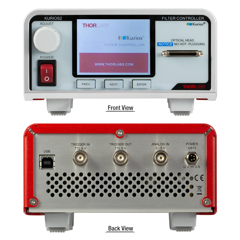
- Designed for Kurios Liquid Crystal Tunable Filter Heads
- Compatible with Narrow, Medium, and Wide Passband Wavelengths
- Includes Kurios Software Package for Remote Operation
- See the Control Tab for More Details
The KURIOS2 Liquid Crystal Tunable Filter Controller is designed specifically for the Kurios tunable bandpass filters sold above. It adjusts the passband wavelength by applying drive voltages to the filter and can be operated manually, externally via an analog control signal, or using the included Kurios Software (see the Control tab for more details). Please note that the optical filter head should be connected before turning the controller on, and hot plugging is not recommended.
Included with the controller is the complete Kurios Software package that accesses all the functions of the KURIOS2 controller (see Software tab for details). Additionally, a full command-line interface can be used for custom software development.