 Products Home
Laser Beam Attenuators
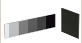
- Neutral Density Attenuation of 29 - 38 dB
- Stacked Prism Design for up to 200 W Max Power
- 30 mm Cage Compatible and Post Mountable
Back
Front
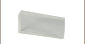
ATT30
Prism Attenuator,
Uncoated
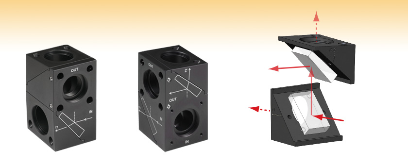
T2 Port Transmission
(~5-10% Intensity)
Input Beam
(100% Intensity)
Reflected Output Beam
(~0.05% Intensity)
T1 Port Transmission
(~90-95% Intensity)


Please Wait
| Key Specsa | ||
|---|---|---|
| Input & Output Apertures | Ø19 mm | |
| Attenuationb | ATT30 Series | 29 to 34 dB |
| ATT31 Series | 31 to 38 dB | |
| Wavelength Rangec |
ATT30(/M) | 200 - 2000 nm (Uncoated) |
| ATT30(/M)-UV | AR Coated for 245 - 400 nm | |
| ATT30(/M)-A | AR Coated for 350 - 700 nm | |
| ATT30(/M)-B | AR Coated for 650 - 1050 nm | |
| ATT30(/M)-C | AR Coated for 1050 - 1700 nm | |
| ATT30(/M)-YAG | AR Coated for 532 & 1064 nm | |
| ATT31(/M) | 200 - 8000 nm (Uncoated) | |
| Max Input Power | Uncoated: 200 W AR Coated: 50 W |
|
| Polarization Insensitivity | ≤1° Azimuth, ≤1° Ellipticity | |
Click to Enlarge
Mounting Features
Features
- Ideal for Attenuation Prior to Beam Characterization Applications:
- Beam Profiling: Beam Size, Beam Shape, and Beam Stability
- M2 Measurement: Beam Quality, and Waist Position
- Polarimetry: Ellipticity and Azimuth Angle
- Spectral Analysis
- UV Fused Silica (UVFS) or Calcium Fluoride (CaF2) Prism Substrates
- Uncoated or AR-Coated Prisms (Coatings Applied to Second Surface Only)
- Compatible with 30 mm Cage Systems
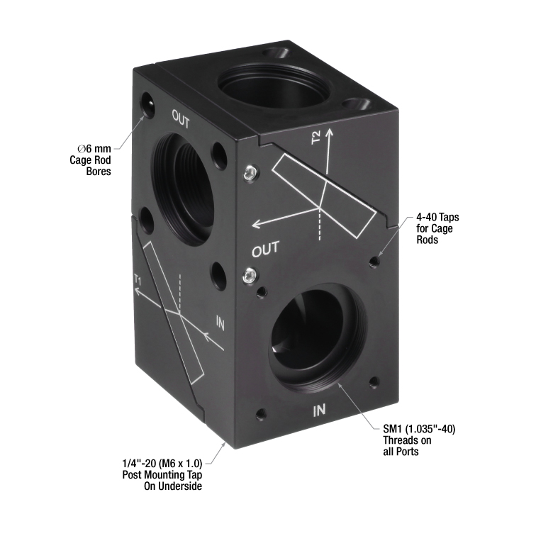
- SM1-Threaded Input, Output, and Beam Dump (T1/T2) Apertures
- 1/4"-20 (M6 x 1.0) Tap for Post Mounting
- Black Anodized Aluminum Housing
Thorlabs' Beam Attenuators use a twofold reflection on two stacked prisms for attenuation of high-power beams up to 200 W (uncoated) or 50 W (AR coated). The ATT30 Series use a pair of UVFS prisms while the ATT31 Series use a pair of CaF2 prisms. AR coatings are only applied to second surfaces for the purpose of reducing secondary beams at the output port caused by multiple reflections at the second surface each prism. The beam attenuation varies smoothly with wavelength (see the Graphs tab).
The two compensating reflections preserve the polarization, size, and shape of the beam, allowing these attenuators to be used with polarization instrumentation while minimizing the effects on the measurement. The prisms transmit up to 95% of the light through the transmission apertures (labeled T1 and T2 in the diagram above). Beam blocks or traps (not included) should be installed on the transmission ports of the attenuators to capture any high residual laser power.
For ease of integration with our 30 mm cage systems, the housings feature 4-40 mounting threads around the input port and Ø6 mm bores for cage rods around the output port. All ports feature SM1 (1.035"-40) internal threads for mounting lens tubes or other SM1-threaded optomechanics. These mounting features also allow tandem positioning to enhance the attenuation. To discuss potential custom AR coating wavelengths not available below, please contact Tech Sales.
| Specificationsa | |||
|---|---|---|---|
| ATT30 Series | ATT31 Series | ||
| Optical Specs | |||
| Prism Substrate | UV Fused Silicab | Calcium Fluorideb | |
| Designed Wavelength Range | 200 nm - 2000 nm | 200 nm - 8000 nm | |
| Typical Attenuationc,d | 29 - 34 dB | 31 - 38 dB | |
| Polarization Insensitivity | ≤1° Azimuth ≤1° Ellipticity |
||
| Surface Quality | 20-10 Scratch-Dig | 40-20 Scratch-Dig | |
| Surface Flatness | <λ/4 at 633 nm | ||
| Exit Angle of Reflected Beam on each Prism |
90° ± 10° arcmin | ||
| Mechanical Specs | |||
| Input Aperture | Ø19 mm (Ø0.75") | ||
| Dimensions | 44.0 mm x 76.5 mm x 44.0 mm (1.73" x 3.01" x 1.73") |
||
| Mass | 0.303 kg (0.668 lbs) | ||
| Operating Conditions | |||
| Operating Temperature | 0 to 40° C | ||
| Storage Temperature | -40 to 70° C | ||
| Item # | AR Coatinga | Wavelength Range | Max Input Power | LIDTb |
|---|---|---|---|---|
| ATT30 Series | ||||
| ATT30(/M) | Uncoated | 200 nm - 2000 nm | 200 W | 10 kW/cm2 15 J/cm2 |
| ATT30(/M)-UV | UV | 245 nm - 400 nm | 50 W | 400 W/cm2 2 J/cm2 |
| ATT30(/M)-A | Visible | 350 nm - 700 nm | ||
| ATT30(/M)-B | Near-IR | 650 nm - 1050 nm | ||
| ATT30(/M)-C | Near-IR | 1050 nm - 1700 nm | ||
| ATT30(/M)-YAG | Nd:YAG | 532 nm & 1064 nm | ||
| ATT31 Series | ||||
| ATT31(/M) | Uncoated | 200 nm - 8000 nm | 200 W | - |
Click to Enlarge
The graph above is a comparison of ATT30 series prism attenuators with our reflective and absorptive (visible and near-IR) neutral density (ND) filters with optical density (OD) = 3.0. Note that OD = (attenuation in decibels)/10.

In order to illustrate the process of determining whether a given laser system will damage an optic, a number of example calculations of laser induced damage threshold are given below. For assistance with performing similar calculations, we provide a spreadsheet calculator that can be downloaded by clicking the button to the right. To use the calculator, enter the specified LIDT value of the optic under consideration and the relevant parameters of your laser system in the green boxes. The spreadsheet will then calculate a linear power density for CW and pulsed systems, as well as an energy density value for pulsed systems. These values are used to calculate adjusted, scaled LIDT values for the optics based on accepted scaling laws. This calculator assumes a Gaussian beam profile, so a correction factor must be introduced for other beam shapes (uniform, etc.). The LIDT scaling laws are determined from empirical relationships; their accuracy is not guaranteed. Remember that absorption by optics or coatings can significantly reduce LIDT in some spectral regions. These LIDT values are not valid for ultrashort pulses less than one nanosecond in duration.

A Gaussian beam profile has about twice the maximum intensity of a uniform beam profile.
CW Laser Example
Suppose that a CW laser system at 1319 nm produces a 0.5 W Gaussian beam that has a 1/e2 diameter of 10 mm. A naive calculation of the average linear power density of this beam would yield a value of 0.5 W/cm, given by the total power divided by the beam diameter:

However, the maximum power density of a Gaussian beam is about twice the maximum power density of a uniform beam, as shown in the graph to the right. Therefore, a more accurate determination of the maximum linear power density of the system is 1 W/cm.
An AC127-030-C achromatic doublet lens has a specified CW LIDT of 350 W/cm, as tested at 1550 nm. CW damage threshold values typically scale directly with the wavelength of the laser source, so this yields an adjusted LIDT value:

The adjusted LIDT value of 350 W/cm x (1319 nm / 1550 nm) = 298 W/cm is significantly higher than the calculated maximum linear power density of the laser system, so it would be safe to use this doublet lens for this application.
Pulsed Nanosecond Laser Example: Scaling for Different Pulse Durations
Suppose that a pulsed Nd:YAG laser system is frequency tripled to produce a 10 Hz output, consisting of 2 ns output pulses at 355 nm, each with 1 J of energy, in a Gaussian beam with a 1.9 cm beam diameter (1/e2). The average energy density of each pulse is found by dividing the pulse energy by the beam area:

As described above, the maximum energy density of a Gaussian beam is about twice the average energy density. So, the maximum energy density of this beam is ~0.7 J/cm2.
The energy density of the beam can be compared to the LIDT values of 1 J/cm2 and 3.5 J/cm2 for a BB1-E01 broadband dielectric mirror and an NB1-K08 Nd:YAG laser line mirror, respectively. Both of these LIDT values, while measured at 355 nm, were determined with a 10 ns pulsed laser at 10 Hz. Therefore, an adjustment must be applied for the shorter pulse duration of the system under consideration. As described on the previous tab, LIDT values in the nanosecond pulse regime scale with the square root of the laser pulse duration:

This adjustment factor results in LIDT values of 0.45 J/cm2 for the BB1-E01 broadband mirror and 1.6 J/cm2 for the Nd:YAG laser line mirror, which are to be compared with the 0.7 J/cm2 maximum energy density of the beam. While the broadband mirror would likely be damaged by the laser, the more specialized laser line mirror is appropriate for use with this system.
Pulsed Nanosecond Laser Example: Scaling for Different Wavelengths
Suppose that a pulsed laser system emits 10 ns pulses at 2.5 Hz, each with 100 mJ of energy at 1064 nm in a 16 mm diameter beam (1/e2) that must be attenuated with a neutral density filter. For a Gaussian output, these specifications result in a maximum energy density of 0.1 J/cm2. The damage threshold of an NDUV10A Ø25 mm, OD 1.0, reflective neutral density filter is 0.05 J/cm2 for 10 ns pulses at 355 nm, while the damage threshold of the similar NE10A absorptive filter is 10 J/cm2 for 10 ns pulses at 532 nm. As described on the previous tab, the LIDT value of an optic scales with the square root of the wavelength in the nanosecond pulse regime:

This scaling gives adjusted LIDT values of 0.08 J/cm2 for the reflective filter and 14 J/cm2 for the absorptive filter. In this case, the absorptive filter is the best choice in order to avoid optical damage.
Pulsed Microsecond Laser Example
Consider a laser system that produces 1 µs pulses, each containing 150 µJ of energy at a repetition rate of 50 kHz, resulting in a relatively high duty cycle of 5%. This system falls somewhere between the regimes of CW and pulsed laser induced damage, and could potentially damage an optic by mechanisms associated with either regime. As a result, both CW and pulsed LIDT values must be compared to the properties of the laser system to ensure safe operation.
If this relatively long-pulse laser emits a Gaussian 12.7 mm diameter beam (1/e2) at 980 nm, then the resulting output has a linear power density of 5.9 W/cm and an energy density of 1.2 x 10⁻⁴ J/cm2 per pulse. This can be compared to the LIDT values for a WPQ10E-980 polymer zero-order quarter-wave plate, which are 5 W/cm for CW radiation at 810 nm and 5 J/cm2 for a 10 ns pulse at 810 nm. As before, the CW LIDT of the optic scales linearly with the laser wavelength, resulting in an adjusted CW value of 6 W/cm at 980 nm. On the other hand, the pulsed LIDT scales with the square root of the laser wavelength and the square root of the pulse duration, resulting in an adjusted value of 55 J/cm2 for a 1 µs pulse at 980 nm. The pulsed LIDT of the optic is significantly greater than the energy density of the laser pulse, so individual pulses will not damage the wave plate. However, the large average linear power density of the laser system may cause thermal damage to the optic, much like a high-power CW beam.
| Posted Comments: | |
Christopher Barton
(posted 2024-08-22 17:17:04.51) Has Thorlabs looked into producing a beam attenuator setup for higher maximum powers. This seems like a good application for the high LIDT nanotube based AR coatings. hkarpenko
(posted 2024-08-26 07:35:29.0) Dear Christopher,
thank you for your feedback.
We are steadily expanding our catalogue and thus rely on such feedbacks as yours to understand what are the needs and applications of our customers. Currently we are not working on an even higher power attenuator, but this is definetly something we consider for future developments. user
(posted 2024-03-12 14:17:11.69) Hello. We are planning to use the ATT30/M - B, ATT30/M - C, and ATT30/M - YAG products as attenuators for FemtoTrain femtosecond laser applications in our laboratory. Could you please confirm if these three attenuators provide consistent attenuation effects when used with a femtosecond laser? The FemtoTrain femtosecond laser has an average power of 5W, wavelengths of 1040nm and 520nm, and a repetition rate of 10 MHz. Additionally, the pulse width is approximately 220 fs. dpossin
(posted 2024-03-12 05:27:38.0) Dear Dash,
Thank you for your feedback. I reach out to you in order to discuss this further. Juriy Hastanin
(posted 2023-05-12 12:48:10.907) Hello,
Could you tell me what is the Exit Angle at 'Transmission T1' output of the Laser Beam Attenuator ATT30/M (200 - 2000 nm, Uncoated) ?
(Since, in this beam attenuator, there are wedged prisms, the transmission T1 output beam is not strictly parallel to the input beam. Accordingly, I needs to know this relative angular deviation (in order to properly integrate your Laser Beam Attenuator in my optical system)
Thanks in advance.
Best regards, dpossin
(posted 2023-05-16 11:36:43.0) Dear Juriy,
Thank you for your feedback. Without knowing the wavelength of your laser I could not calculate the output angle relative to the housing. The wedged prisms used in the ATT30 you can find here: https://www.thorlabs.com/newgrouppage9.cfm?objectgroup_id=6249. Please also have a look at the theory tab.
I am reaching out to you for further discussion. Steven Cheng
(posted 2023-03-28 19:34:56.223) Hello,
I wanna know about this product how to address the optical power attenuations and how to input and output the optical beam.
Notes:
Our laser input with SMA905 connectors and 760um of type fiber. Output with FC/PC connectors and 9/125um of type fiber.
Hope to get your response asap!
Br,
Steven in China hchow
(posted 2023-03-31 10:42:18.0) Dear Mr. Cheng, thank you for your feedback. I will personally reach out to you to discuss possible solutions. Thank you. Priscilla Vazquez
(posted 2022-08-15 11:37:11.44) Hi! I'd like to know if you have a Zemax model for this beam attenuator or if you have specs for the optics so I can model it myself.
Thanks! dpossin
(posted 2022-08-16 04:45:16.0) Dear Priscilla,
Thank you for your feedback. The information you are looking for already is presented on the specs tabe on the product page of the ATT30. For the substrate We use UV fused silica and our coatings for different wavelengths. I contact you directly in order to clear up further questions. Lennart Hirsch
(posted 2022-08-01 14:42:49.993) Seems very difficult to use. None of the spots reflect at 90 degrees to the input angle, (especially not the 1st reflection).
Additionally, and more importantly, the 1st reflection clips on the edge of the mount. Even if I move the device to change the position of the input beam, a beam profiler shows that the 1st reflection clips and suffers from aberrations due to diffraction off the edge of the output aperture. The 4th reflection is actually the cleanest exiting reflection out of the 4, which strikes me as odd as this is the last reflection I would want to use.
I'm not sure if I'm missing something or doing something wrong, or if perhaps the wedges have been installed incorrectly. dpossin
(posted 2022-08-02 08:09:46.0) Dear Lennart,
Thank you for your feedback. I reach out directly to you in order to discuss this in more detail. Martin Redeby
(posted 2021-10-08 05:21:14.107) I don't see a specified length of the beampath, please add (even though it is easy to calculate).
also a half size sm0.5 version would be awesome! nreusch
(posted 2021-10-15 06:46:32.0) Thank you for your feedback and your suggestion, we will consider adding a 1/2’’ version in the future. The length of the beam path is 76.2 mm (3’’). |
| Item # | AR Coating | Prism Substrate | Designed Wavelength Range | Typical Attenuationa,b | Max Input Power |
|---|---|---|---|---|---|
| ATT30(/M) | Uncoated | UV Fused Silica | 200 nm - 2000 nm | 29 to 34 dB | 200 W |
| ATT30-UV(/M) | UV | 245 nm - 400 nm | 50 W | ||
| ATT30-A(/M) | Visible | 350 nm - 700 nm | |||
| ATT30-B(/M) | Near-IR | 650 nm - 1050 nm | |||
| ATT30-C(/M) | Near-IR | 1050 nm - 1700 nm | |||
| ATT30-YAG(/M) | YAG | 532 nm & 1064 nm |