 Products Home / Incoherent Sources / Superluminescent Diodes (SLDs) / NIR Superluminescent Diodes (SLDs)
NIR Superluminescent Diodes (SLDs)
- Broadband Emission Wavelengths from 770 nm to 1610 nm
- Low Ripple
- Butterfly Package
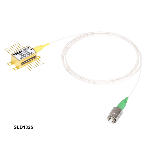
SLD1325
1325 nm SLD, >100 nm Bandwidth
30 dB (Min) Optical Isolation
Application Idea
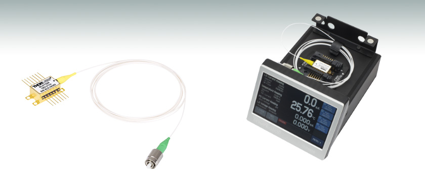
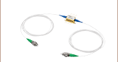
SLD1550S-A2
Superluminescent Diode
Mounted in a CLD1015 Compact
Laser Diode Driver with TEC


Please Wait
| Recommended Controller / Mount Options | |||
|---|---|---|---|
| Item # | Mount | Diode Driver | TEC Controller |
| CLD1015 | |||
| LM14S2 | - | - | |
| ITC4000 Series | Use with LM14S2 Mount | ||
| LDC200 Series | Use with LM14S2 Mount | - | |
| TED200C | Use with LM14S2 Mount | - | |
Features
- Center Wavelengths from 770 nm to 1610 nm
- Typical 3 dB Bandwidths Ranging from 18 to 110 nm
- 1220 nm, 1315 nm, 1325 nm, and 1400 nm Center Wavelength SLDs Available from Stock with Integrated Optical Isolator
- 14-Pin Butterfly Package Pigtailed with ≥1 m of SM or PM Fiber
- 2.0 mm Narrow Key FC/APC Connector
- Integrated TEC and Thermistor
Superluminescent Diodes (SLDs) are excellent high-power, broadband light sources that are ideal for use in applications such as Optical Coherence Tomography (OCT) Imaging Systems and Fiber Optic Gyroscopes (FOG).
| Quick Links | ||
|---|---|---|
| 770 - 850 nm | 880 - 1220 nm | 1310 - 1610 nm |
| 770 nm (SM) | 880 nm (SM) | 1310 nm (SM or PM) |
| 810 nm (SM) | 920 nm (SM or PM) | 1315 nm (SM or PM) |
| 830 nm (SM) | 930 nm (SM or PM) | 1325 nm (SM or PM) |
| 840 nm (SM or PM) | 970 nm (SM or PM) | 1400 nm (SM or PM) |
| 850 nm (SM) | 1050 nm (SM or PM) | 1450 nm (SM or PM) |
| - | 1220 nm (SM or PM) | 1550 nm (SM or PM) |
| - | - | 1610 nm (SM or PM) |
Thorlabs offers NIR SLDs with center wavelengths from 770 nm to 1610 nm (see the Quick Links table to the right). The butterfly-packaged SLDs offered here up to 1100 nm are gallium arsenide (GaAs) substrate based and the rest are indium phosphide (InP) devices.
Each device is built into a 14-pin butterfly package with an integrated thermoelectric cooler (TEC) and thermistor to ensure output stability. The output is coupled into an SM or PM fiber terminated with a 2.0 mm narrow key FC/APC connector. Please note that optical feedback can diminish the output power or damage the SLD. We do not recommend using these SLDs with components that are prone to back reflections, such as FC/PC connectors. The SLD1220x, SLD1310x, SLD1325, SLD1330x, and SLD1410x superluminescent diodes incorporate an integrated optical isolator. If you are interested in an SLD at a different wavelength with an integrated isolator, please contact Tech Support with inquiries.
Full Specifications are available by clicking on the Specs tab above. Each SLD is shipped with an individualized product data sheet, which includes information on the spectrum and operating parameters of the device. Test data for a specific SLD can be requested by contacting Tech Support.
For spectra comparison graphs, see the Spectral Comparison tab. The SLDs featured on this page have either a near-Gaussian or flat-top optical spectrum. The calculation for the center wavelength differs with these two spectral shapes. Please see the Specs tab for center wavelength calculations.
Thorlabs is able to provide low-ripple SLDs with custom wavelengths or higher power diodes. Please note that the engineering design and wafer manufacturing costs involved make the purchase of low quantities very costly. For a quote on custom SLDs, please contact Tech Support. A selection of the SLDs sold here are also available as benchtop sources. For more information, see the Selection Guide tab.
Due to the nature of producing superluminescent diodes with ultra wide bandwidths, some of the SLDs sold below have spectral shapes that are near gaussian, while others have a shape with a flattened top. This difference in spectral shape demands two different methods of defining center wavelength in order to provide an accurate description of the diode.
Near-Guassian Center Wavelength Definition
The center wavelength for devices with a near-gaussian spectral shape is defined by an average weighted by the relative amplitude and may not correspond to peak power or the FWHM center wavelength due to the variability of the spectrum shape. For a given Optical Spectrum Analyzer (OSA) trace:
where
- CW is the Specified Center Wavelength
- Xi is the Wavelength of a Trace Data Point
- Yi is the Amplitude of a Trace Data Point
Flat-Top Center Wavelength Definition
The center wavelength for devices with a flat-top spectral shape is defined by the midpoint between the two wavelengths located at 3 dB below the maximum intensity point on the spectrum. For a given OSA trace:
where
- CW is the Specified Center Wavelength
- XR_3dB is the Right Wavelength Edge of the 3 dB Bandwidth
- XL_3dB is the Left Wavelength Edge of the 3 dB Bandwidth
SLD Specifications
Note that these specifications are given as guidelines. The characterization sheet shipped with each SLD provides the minimum, maximum, and recommended operating parameters and specifications specific to that device. The ASE Power specification is the output from the fiber pigtail.
770 nm CWL Superluminescent Diode
| Item # | SLD770S | ||
|---|---|---|---|
| Parametera | Min | Typ. | Max |
| Operating Current | - | - | 170 mA |
| Center Wavelength (CWL)b | 760 nm | 770 nm | 780 nm |
| Spectral Shape | Near Gaussian | ||
| ASE Powerc | 4.5 mW | 5.5 mW | - |
| Optical 3 dB Bandwidthc,d | 15 nm | 18 nm | - |
| RMS Gain Ripplec | - | 0.01 dB | 0.3 dB |
| Forward Voltagec | - | 1.95 V | 2.5 V |
| Fiber Type | 780HP (SM) | ||
| TEC Operation: Typ. / Max @ TCASE = 25 °C / 70 °C | |||
| TEC Current | - | 0.11 A | 1.4 A |
| TEC Voltage | - | 0.16 V | 4.0 V |
| Thermistor Resistance | - | 10 kΩ | - |
| Performance Graphs (Click Icons for Plots) | |||
| Output Spectrum |  |
||
| LIV Plot |  |
||
| Gain Ripplec,e |  |
||
| Absolute Maximum Ratingsa | |||
| Absolute Max Current | 170 mA | ||
| Operating Case Temperature | 0 to 70 °C | ||
| Storage Temperature | -10 to 70 °C | ||
| Pin Code | 14 Pin, Type 1 | ||
810 nm CWL Superluminescent Diodes
| Item # | SLD810S | |||||
|---|---|---|---|---|---|---|
| Parametera | Min | Typical | Max | |||
| Operating Current | - | - | 270 mA | |||
| Center Wavelength (CWL)b | 795 nm | 810 nm | 825 nm | |||
| Spectral Shape | Near Gaussian | |||||
| ASE Powerc | 13 mW | 15 mW | - | |||
| Optical 3 dB Bandwidthc,d | 25 nm | 30 nm | - | |||
| RMS Gain Ripplec | - | 0.03 dB | 0.15 dB | |||
| Forward Voltage | - | 2.1 V | 2.5 V | |||
| Fiber | 780HP (SM) | |||||
| TEC Operation: Typ. / Max @ TCASE = 25 °C / 70 °C | ||||||
| TEC Current | - | 0.2 A | 1.4 A | |||
| TEC Voltage | - | 0.3 V | 6.0 V | |||
| Thermistor Resistance | - | 10 kΩ | - | |||
| Performance Graphs (Click Icons for Plots) | ||||||
| Output Spectrum | ||||||
| LIV Plot | ||||||
| Gain Ripplec,e | ||||||
| Absolute Maximum Ratingsa | ||||||
| Absolute Max Current | 290 mA | |||||
| Operating Case Temperature | 0 to 70 °C | |||||
| Storage Temperature | -10 to 70 °C | |||||
| Pin Code | 14 Pin, Type 1 | |||||
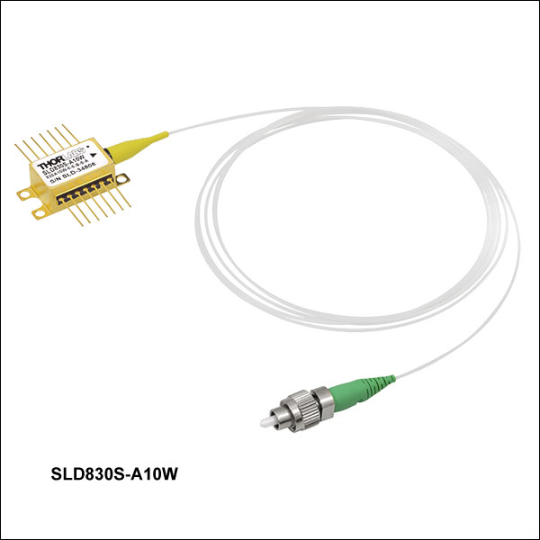
830 nm CWL Superluminescent Diodes
| Item # | SLD830S-A10W | SLD830S-A20W | SLD830S-A10 | SLD830S-A20 | ||||||||
|---|---|---|---|---|---|---|---|---|---|---|---|---|
| Parametera | Min | Typical | Max | Min | Typical | Max | Min | Typical | Max | Min | Typical | Max |
| Operating Current | - | - | 240 mA | - | - | 330 mA | - | - | 150 mA | - | - | 240 mA |
| Center Wavelength (CWL)b | 815 nm | 830 nm | 845 nm | 815 nm | 830 nm | 845 nm | 820 nm | 830 nm | 840 nm | 820 nm | 830 nm | 840 nm |
| Spectral Shape | Flat Top | Flat Top | Near Gaussian | Near Gaussian | ||||||||
| ASE Powerc,d | 10 mW | - | - | 20 mW | - | - | 10 mW | 13 mW | - | 20 mW | 22 mW | - |
| Optical 3 dB Bandwidthc,e | 50 nm | 60 nm | - | 40 nm | 55 nm | - | 17 nm | 20 nm | - | 17 nm | 20 nm | - |
| Optical 20 dB Bandwidthc | - | - | - | - | - | - | - | 50 nm | - | - | 50 nm | - |
| RMS Gain Ripplec,f | - | 0.06 dB | 0.3 dB | - | 0.03 dB | 0.3 dB | - | 0.03 dB | 0.15 dB | - | 0.03 dB | 0.15 dB |
| Forward Voltage | - | 2.0 V | 2.5 V | - | 2.0 V | 2.5 V | - | 2.0 V | 2.5 V | - | 2.0 V | 2.5 V |
| Fiber Type | 780HP | 780HP | 780HP | 780HP | ||||||||
| TEC Operation: Typ. / Max @ TCASE = 25 °C / 70 °C | ||||||||||||
| TEC Current | - | 0.14 A | 1.4 A | - | 0.14 A | 1.4 A | - | 0.1 A | 1.5 A | - | 0.1 A | 1.5 A |
| TEC Voltage | - | 0.18 V | 6.0 V | - | 0.18 V | 6.0 V | - | 0.13 V | 4.0 V | - | 0.13 V | 4.0 V |
| Thermistor Resistance | - | 10 kΩ | - | - | 10 kΩ | - | - | 10 kΩ | - | - | 10 kΩ | - |
| Performance Graphs (Click Icons for Plots) | ||||||||||||
| Output Spectrum | ||||||||||||
| LIV Plot | ||||||||||||
| Gain Ripplef | ||||||||||||
| Absolute Maximum Ratingsa | ||||||||||||
| Absolute Max Current | 240 mA | 330 mA | 150 mA | 240 mA | ||||||||
| Operating Case Temperature | 0 to 70 °C | 0 to 70 °C | 0 to 70 °C | 0 to 70 °C | ||||||||
| Storage Temperature | -10 to 70 °C | -10 to 70 °C | -10 to 70 °C | -10 to 70 °C | ||||||||
| Pin Code | 14 Pin, Type 1 | 14 Pin, Type 1 | 14 Pin, Type 1 | 14 Pin, Type 1 | ||||||||
840 nm CWL Superluminescent Diodes
| Item # | SLD840x | |||||
|---|---|---|---|---|---|---|
| Parametera | Min | Typical | Max | |||
| Operating Current | - | 140 mA | 180 mA | |||
| Center Wavelength (CWL)b | 820 nm | 840 nm | 860 nm | |||
| Spectral Shape | Flat Top | |||||
| ASE Powerc,d | 3 mW | 4 mW | - | |||
| Optical 3 dB Bandwidthc,e | 60 nm | 70 nm | - | |||
| RMS Gain Ripplec,f | - | 0.01 dB | 0.1 dB | |||
| Forward Voltage | - | 2.0 V | 2.5 V | |||
| Fiber | 780HP (SM) PM780-HP (PM)g |
|||||
| TEC Operation: Typ. / Max @ TCASE = 25 °C / 70 °C | ||||||
| TEC Current | - | 0.1 A | 1.5 A | |||
| TEC Voltage | - | 0.15 V | 4.0 V | |||
| Thermistor Resistance | - | 10 kΩ | - | |||
| Performance Graphs (Click Icons for Plots) | ||||||
| Output Spectrum |
|
|||||
| LIV Plot |
|
|||||
| Gain Ripplef |
|
|||||
| Absolute Maximum Ratingsa | ||||||
| Absolute Max Current | 180 mA | |||||
| Operating Case Temperature | 0 °C to 70 °C | |||||
| Storage Temperature | -10 °C to 70 °C | |||||
| Pin Code | 14 Pin, Type 1 | |||||
850 nm CWL Superluminescent Diodes
| Item # | SLD850S-A10W | SLD850S-A20W | ||||
|---|---|---|---|---|---|---|
| Parametera | Min | Typical | Max | Min | Typical | Max |
| Operating Current | - | - | 180 mA | - | - | 340 mA |
| Center Wavelength (CWL)b | 835 nm | 850 nm | 865 nm | 835 nm | 850 nm | 865 nm |
| Spectral Shape | Flat Top | Flat Top | ||||
| ASE Powerc,d | 10 mW | - | - | 20 mW | - | - |
| Optical 3 dB Bandwidthc,e | 40 nm | 60 nm | - | 40 nm | 55 nm | - |
| RMS Gain Ripplec,f | - | 0.03 dB | 0.3 dB | - | 0.03 dB | 0.3 dB |
| Forward Voltage | - | 2.0 V | 2.5 V | - | 2.0 V | 2.5 V |
| Fiber Type | 780HP | 780HP | ||||
| TEC Operation: Typ. / Max @ TCASE = 25 °C / 70 °C | ||||||
| TEC Current | - | 0.11 A | 1.4 A | - | 0.18 A | 1.4 A |
| TEC Voltage | - | 0.17 V | 6.0 V | - | 0.27 V | 6.0 V |
| Thermistor Resistance | - | 10 kΩ | - | - | 10 kΩ | - |
| Performance Graphs (Click Icons for Plots) | ||||||
| Output Spectrum | ||||||
| LIV Plot | ||||||
| Gain Ripplef | ||||||
| Absolute Maximum Ratingsa | ||||||
| Absolute Max Current | 180 mA | 340 mA | ||||
| Operating Case Temperature | 0 to 70 °C | 0 to 70 °C | ||||
| Storage Temperature | -10 to 70 °C | -10 to 70 °C | ||||
| Pin Code | 14 Pin, Type 1 | 14 Pin, Type 1 | ||||
880 nm CWL Superluminescent Diodes
| Item # | SLD880S-A7 | SLD880S-A25 | ||||
|---|---|---|---|---|---|---|
| Parametera | Min | Typical | Max | Min | Typical | Max |
| Operating Current | - | - | 225 mA | - | - | 410 mA |
| Center Wavelength (CWL)b | 860 nm | 880 nm | 900 nm | 860 nm | 880 nm | 900 nm |
| Spectral Shape | Flat Top | Flat Top | ||||
| ASE Powerc,d | 6 mW | 7 mW | - | 23 mW | 25 mW | - |
| Optical 3 dB Bandwidthc | 35 nm | 40 nm | - | 35 nm | 40 nm | - |
| Optical 20 dB Bandwidthc | - | 80 nm | - | - | 80 nm | - |
| RMS Gain Ripplec,e | - | 0.06 dB | 0.3 dB | - | 0.06 dB | 0.3 dB |
| Forward Voltagec | - | 2.0 V | 2.5 V | - | 2.0 V | 2.5 V |
| Fiber Type | 780HP | 780HP | ||||
| TEC Operation: Typ. / Max @ TCASE = 25 °C / 70 °C | ||||||
| TEC Current | - | 0.2 A | 1.4 A | - | 0.2 A | 1.4 A |
| TEC Voltage | - | 0.8 V | 6.0 V | - | 0.8 V | 6.0 V |
| Thermistor Resistance | - | 10 kΩ | - | - | 10 kΩ | - |
| Performance Graphs (Click Icons for Plots) | ||||||
| Output Spectrum | ||||||
| LIV Plot | ||||||
| Gain Ripplee | ||||||
| Absolute Maximum Ratingsa | ||||||
| Absolute Max Current | 225 mA | 410 mA | ||||
| Operating Case Temperature | 0 to 70 °C | 0 to 70 °C | ||||
| Storage Temperature | -10 to 70 °C | -10 to 70 °C | ||||
| Pin Code | 14 Pin, Type 1 | 14 Pin, Type 1 | ||||
920 nm CWL Superluminescent Diodes
| Item # | SLD920x | |||||
|---|---|---|---|---|---|---|
| Parametera | Min | Typical | Max | |||
| Operating Current | - | - | 420 mA | |||
| Center Wavelength (CWL)b | 895 nm | 920 nm | 945 nm | |||
| Spectral Shape | Flat Top | |||||
| ASE Powerc,d | 10 mW | 15 mW | - | |||
| Optical 3 dB Bandwidthc,e | 50 nm | 65 nm | - | |||
| RMS Gain Ripplec,f | - | 0.02 dB | 0.3 dB | |||
| Forward Voltage | - | 2.0 V | 2.5 V | |||
| Fiber | 780HP (SM) PM780-HP (PM)g |
|||||
| TEC Operation: Typ. / Max @ TCASE = 25 °C / 70 °C | ||||||
| TEC Current | - | 0.3 A | 1.4 A | |||
| TEC Voltage | - | 0.4 V | 6.0 V | |||
| Thermistor Resistance | - | 10 kΩ | - | |||
| Performance Graphs (Click Icons for Plots) | ||||||
| Output Spectrum | ||||||
| LIV Plot | ||||||
| Gain Ripplee | ||||||
| Absolute Maximum Ratingsa | ||||||
| Absolute Max Current | 420 mA | |||||
| Operating Case Temperature | 0 °C to 70 °C | |||||
| Storage Temperature | -10 °C to 70 °C | |||||
| Pin Code | 14 Pin, Type 1 | |||||
930 nm CWL Superluminescent Diodes
| Item # | SLD930x-A40W | |||||
|---|---|---|---|---|---|---|
| Parametera | Min | Typical | Max | |||
| Operating Current | - | - | 800 mA | |||
| Center Wavelength (CWL)b | 915 nm | 930 nm | 945 nm | |||
| Spectral Shape | Flat Top | |||||
| ASE Powerc,d | 36 mW | 40 mW | - | |||
| Optical 3 dB Bandwidthc,e | 40 nm | 45 nm | - | |||
| RMS Gain Ripplec,f | - | 0.06 dB | 0.3 dB | |||
| Forward Voltage | - | 2.0 V | 2.5 V | |||
| Fiber | 780HP (SM) PM780-HP (PM)g |
|||||
| TEC Operation: Typ. / Max @ TCASE = 25 °C / 70 °C | ||||||
| TEC Current | - | 0.54 A | 1.4 A | |||
| TEC Voltage | - | 0.78 V | 6.0 V | |||
| Thermistor Resistance | - | 10 kΩ | - | |||
| Performance Graphs (Click Icons for Plots) | ||||||
| Output Spectrum |
|
|||||
| LIV Plot |
|
|||||
| Gain Ripplef |
|
|||||
| Absolute Maximum Ratingsa | ||||||
| Absolute Max Current | 800 mA | |||||
| Operating Case Temperature | 0 °C to 70 °C | |||||
| Storage Temperature | -10 °C to 70 °C | |||||
| Pin Code | 14 Pin, Type 1 | |||||
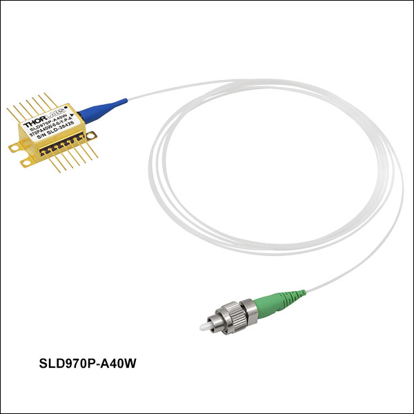
970 nm CWL Superluminescent Diodes
| Item # | SLD970x-A40W | ||
|---|---|---|---|
| Parametera | Min | Typical | Max |
| Operating Current | - | 1000 mA | 1010 mA |
| Center Wavelength (CWL)b | 945 nm | 970 nm | 995 nm |
| Spectral Shape | Flat Top | ||
| ASE Powerc,d | 35 mW | 40 mW | - |
| Optical 3 dB Bandwidthc,e | 40 nm | 50 nm | - |
| RMS Gain Ripplec,f | - | 0.03 dB | 0.2 dB |
| Forward Voltage | - | 1.2 V | 2.5 V |
| Fiber Type | HI1060 (SM) PM980-XP (PM)g |
||
| TEC Operation: Typ. / Max @ TCASE = 25 °C / 70 °C | |||
| TEC Current | - | 0.83 A | 1.4 A |
| TEC Voltage | - | 0.12 V | 6.0 V |
| Thermistor Resistance | - | 10 kΩ | - |
| Performance Graphs (Click Icons for Plots) | |||
| Output Spectrum | |||
| LIV Plot | |||
| Gain Ripplef | |||
| Absolute Maximum Ratingsa | |||
| Absolute Max Current | 1010 mA | ||
| Operating Case Temperature | 0 °C to 70 °C | ||
| Storage Temperature | -10 °C to 70 °C | ||
| Pin Code | 14 Pin, Type 1 | ||
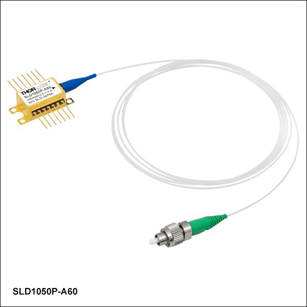
1050 nm CWL Superluminescent Diodes
| Item # | SLD1050x | SLD1050S-A60 | SLD1050P-A60 | |||||||||
|---|---|---|---|---|---|---|---|---|---|---|---|---|
| Parametera | Min | Typical | Max | Min | Typical | Max | Min | Typical | Max | |||
| Operating Current | - | - | 300 mA | - | - | 1010 mA | - | - | 1010 mA | |||
| Center Wavelength (CWL)b | 1030 nm | 1050 nm | 1070 nm | 1025 nm | 1050 nm | 1075 nm | 1025 nm | 1050 nm | 1075 nm | |||
| Spectral Shape | Near Gaussian | Flat Top | Flat Top | |||||||||
| ASE Powerc,d | 6 mW | 8 mW | - | 55 mW | 60 mW | - | 55 mW | 60 mW | - | |||
| Optical 3 dB Bandwidthc,e | 40 nm | 50 nm | - | 60 nm | 70 nm | - | 60 nm | 70 nm | - | |||
| Optical 20 dB Bandwidthc | - | - | - | - | 100 nm | - | - | - | - | |||
| RMS Gain Ripplec,f | - | 0.1 dB | 0.25 dB | - | 0.03 dB | 0.2 dB | - | 0.06 dB | 0.3 dB | |||
| Forward Voltagec | - | 2.0 V | 2.5 V | - | 2.0 V | 2.5 V | - | 1.9 V | 2.5 V | |||
| Fiber Type | HI1060 (SM) PM980-XP (PM)g |
HI1060 | PM980-XPg | |||||||||
| TEC Operation: Typ. / Max @ TCASE = 25 °C / 70 °C | ||||||||||||
| TEC Current | - | 0.25 A | 1.5 A | - | 0.7 A | 2.5 A | - | 0.7 A | 2.5 A | |||
| TEC Voltage | - | 0.30 V | 4.0 V | - | 0.9 V | 3.2 V | - | 1.0 V | 3.2 V | |||
| Thermistor Resistance | - | 10 kΩ | - | - | 10 kΩ | - | - | 10 kΩ | - | |||
| Performance Graphs (Click Icons for Plots) | ||||||||||||
| Output Spectrum |
|
|||||||||||
| LIV Plot |
|
|||||||||||
| Gain Ripplef | - | |||||||||||
| Absolute Maximum Ratingsa | ||||||||||||
| Absolute Max Current | 360 mA | 1010 mA | 1010 mA | |||||||||
| Operating Case Temperature | 0 °C to 70 °C | 0 °C to 70 °C | 0 °C to 70 °C | |||||||||
| Storage Temperature | - | -10 °C to 70 °C | -10 °C to 70 °C | |||||||||
| Chip Temperature (TEC) | 10 °C to 30 °C | - | - | |||||||||
| Pin Code | 14 Pin, Type 1 | 14 Pin, Type 1 | 14 Pin, Type 1 | |||||||||
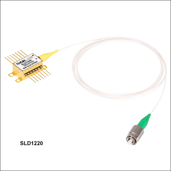
1220 nm CWL Superluminescent Diode
| Item # | SLD1220x | |||||||||||
|---|---|---|---|---|---|---|---|---|---|---|---|---|
| Parametera | Min | Typ. | Max | |||||||||
| Center Wavelength (CWL)b | 1205 nm | 1220 nm | 1235 nm | |||||||||
| Spectral Shape | Flat Top | |||||||||||
| Operating Current | - | 400 mA | 450 mA | |||||||||
| ASE Powerc,d | 4 mW | 5 mW | - | |||||||||
| Optical 3 dB Bandwidthc,e | 85 nm | 90 nm | - | |||||||||
| RMS Gain Ripplec,f | - | 0.05 dB | 0.35 dB | |||||||||
| Forward Voltagec | - | 1.7 V | 2.0 V | |||||||||
| TEC Operation: Typ. / Max @ TCASE = 25 °C / 70 °C | ||||||||||||
| TEC Current | - | 0.28 A | 1.5 A | |||||||||
| TEC Voltage | - | 0.39 V | 3.5 V | |||||||||
| Thermistor Resistance | - | 10 kΩ | - | |||||||||
| Integrated Isolator | ||||||||||||
| Isolation | - | 50 dB | - | |||||||||
| Performance Graphs (Click Icons for Plots) | ||||||||||||
| Output Spectrum |
|
|||||||||||
| LIV Plot |
|
|||||||||||
| Absolute Maximum Ratingsg | ||||||||||||
| Absolute Max Current | 1.5 A | |||||||||||
| Operating Case Temperature | 0 to 70 °C | |||||||||||
| Storage Temperature | -10 to 70 °C | |||||||||||
| Pin Code | 14 Pin, Type 1 | |||||||||||
| Fiber Specifications | ||||||||||||
| Fiber Type | HI1060 (SM) Corning® PM13-U40A (PM) |
|||||||||||
| Numerical Aperture | 0.14 (SM) 0.12 (PM) |
|||||||||||
| Mode Field Diameter (Nominal) | 5.9 ± 0.3 µm @ 980 nm (SM) 6.2 ± 0.3 µm @ 1030 nm (SM) 9.3 ± 0.5 µm @ 1550 nm (PM) |
|||||||||||
| Fiber Length | 1.50 ± 0.05 m | |||||||||||
| Connector | FC/APC, 2.0 mm Narrow Keyh | |||||||||||
1310 nm and 1315 nm CWL Superluminescent Diodes
| Item # | SLD1021S | SLD1018x | SLD1310 | SLD1310P | ||||||||
|---|---|---|---|---|---|---|---|---|---|---|---|---|
| Parametera | Min | Typical | Max | Min | Typical | Max | Min | Typical | Max | Min | Typical | Max |
| Operating Current | - | 700 mA | 900 mA | - | 600 mA | 800 mA | - | 900 mA | 1000 mA | - | 900 mA | 1000 mA |
| Center Wavelength (CWL)b | 1290 nm | - | 1330 nm | 1290 nm | - | 1330 nm | 1300 nm | 1315 nm | 1330 nm | 1300 nm | 1315 nm | 1330 nm |
| Spectral Shape | Near Gaussian | Near Gaussian | Flat Top | Flat Top | ||||||||
| ASE Powerc,d | 10 mW | 12.5 mW | - | 22 mW | 30 mW | - | 22 mW | 30 mW | - | 22 mW | 30 mW | - |
| Optical 3 dB Bandwidthc,d,e | 80 nm | 85 nm | - | 40 nm | 45 nm | - | 75 nm | 90 nm | - | 75 nm | 90 nm | - |
| RMS Gain Ripplec,f | - | - | 0.35 dB | - | 0.1 dB | 0.35 dB | - | 0.12 dB | 0.3 dB | - | 0.12 dB | 0.35 dB |
| Forward Voltagec | - | 1.55 V | 2.0 V | - | 1.5 V | 1.8 V | - | 2.0 V | 2.3 V | - | 1.5 V | 1.8 V |
| Polarization Extinction Ratio (PER) | - | - | - | - | - | - | - | - | - | - | 23 dB | - |
| Fiber Type | SMF-28e+ | SMF-28e+ (SM) Corning PM 13-U40A (PM)g |
SMF-28e | Corning PM13-U40Ag | ||||||||
| TEC Operationh | ||||||||||||
| TEC Current | - | 0.4 A | 1.5 A | - | 0.4 A | 1.5 A | - | 0.7 A | 1.5 A | - | 0.7 A | 1.5 A |
| TEC Voltage | - | 0.5 V | 4 V | - | 0.5 V | 4 V | - | 1.0 V | 4.0 V | - | 1.0 V | 4.0 V |
| Thermistor Resistance | - | 10 kΩ | - | - | 10 kΩ | - | - | 10 kΩ | - | - | 10 kΩ | - |
| Integrated Isolator | ||||||||||||
| Isolation | N/Ai | N/Ai | - | 50 dB | - | - | 50 dB | - | ||||
| Performance Plots (Click Icons for Plots) | ||||||||||||
| Output Spectrum | ||||||||||||
| LIV Plot | ||||||||||||
| Gain Ripplef | - | - | ||||||||||
| Absolute Maximum Ratingsj | ||||||||||||
| Absolute Max Current | - | - | 1000 mA | 1000 mA | ||||||||
| Operating Case Temperature | - | - | 0 °C to 70 °C | 0 °C to 70 °C | ||||||||
| Storage Temperature | - | - | -10 °C to 70 °C | -10 °C to 70 °C | ||||||||
| Pin Code | 14 Pin, Type 1 | 14 Pin, Type 1 | 14 Pin, Type 1 | 14 Pin, Type 1 | ||||||||
1325 nm CWL Superluminescent Diodes
| Item # | SLD1325 | SLD1330 | SLD1330P | ||||||
|---|---|---|---|---|---|---|---|---|---|
| Parametera | Min | Typical | Max | Min | Typical | Max | Min | Typical | Max |
| Operating Current | - | - | 780 mA | - | 1250 mA | 1300 mA | - | 1250 mA | 1300 mA |
| Center Wavelength (CWL)b | - | 1325 nm | - | 1310 nm | 1325 nm | 1340 nm | 1310 nm | 1325 nm | 1340 nm |
| Spectral Shape | Flat Top | Flat Top | Flat Top | ||||||
| ASE Powerc,d | 10 mW | - | - | 35 mW | 40 mW | - | 35 mW | 40 mW | - |
| Optical 3 dB Bandwidthc,d,e | 100 nm | - | - | 80 nm | 90 nm | - | 80 nm | 90 nm | - |
| RMS Gain Ripplec,f | - | - | - | - | 0.1 dB | 0.3 dB | - | 0.1 dB | 0.3 dB |
| Forward Voltage | - | - | 4 V | - | 2.3 V | 2.5 V | - | 2.3 V | 2.5 V |
| Polarization Extinction Ratio (PER) | - | - | - | - | - | - | - | 23 dB | - |
| Operating Temperature Range | 0 to 40 °C | 0 to 70 °C | 0 to 70 °C | ||||||
| TEC Operationg | |||||||||
| TEC Current | - | - | 4 A | - | 1.2 A | 1.5 A | - | 1.2 A | 1.5 A |
| TEC Voltage | - | - | 4 V | - | 1.6 V | 4.0 V | - | 1.6 V | 4.0 V |
| Thermistor Resistance | - | - | 10 kΩ | - | 10 kΩ | - | - | 10 kΩ | - |
| Steinhart-Hart Coefficients | C1 = 1.1291x10⁻³, C2 = 2.3413x10⁻⁴, and C3 = 0.8767x10⁻⁷ | ||||||||
| Integrated Isolator | |||||||||
| Isolation | 30 dB | - | - | - | 50 dB | - | - | 50 dB | - |
| Performance Graphs (Click Icons for Plots) | |||||||||
| Output Spectrum | |||||||||
| LIV Plot | |||||||||
| Gain Ripplef | - | ||||||||
| Absolute Maximum Ratingsh | |||||||||
| Absolute Max Current | - | 1300 mA | 1300 mA | ||||||
| Operating Case Temperature | - | 0 °C to 70 °C | 0 °C to 70 °C | ||||||
| Storage Temperature | - | -10 °C to 70 °C | -10 °C to 70 °C | ||||||
| Pin Code | 14 Pin, Type 1 | 14 Pin, Type 1 | 14 Pin, Type 1 | ||||||
| Fiber Specifications | |||||||||
| Fiber Type | SMF-28+ | SMF-28e | Corning PM13-U40Ai | ||||||
| Numerical Aperture | 0.14 | 0.14 | 0.12 | ||||||
| Core Diameter | 8.2 µm | 8.2 µm | - | ||||||
| Mode Field Diameter | 9.2 ± 0.4 µm @ 1310 nm 10.2 ± 0.5 µm @ 1550 nm |
9.2 ± 0.4 µm @ 1310 nm 10.2 ± 0.5 µm @ 1550 nm |
9.3 ± 0.5 µm @ 1300 nm | ||||||
| Fiber Length | 1.5 m | 1.5 m ± 0.05 m | 1.5 m ± 0.05 m | ||||||
| Connector | FC/APC, 2.0 mm Narrow Key | FC/APC, 2.0 mm Narrow Key | FC/APC, 2.0 mm Narrow Key | ||||||
1400 nm CWL Superluminescent Diode
| Item # | SLD1410x | ||||
|---|---|---|---|---|---|
| Parametera | Min | Typical | Max | ||
| Operating Current | - | 600 mA | 700 mA | ||
| Center Wavelength (CWL)b | 1385 nm | 1400 nm | 1415 nm | ||
| Spectral Shape | Near Gaussian | ||||
| ASE Powerc,d | 4 mW | 5 mW | - | ||
| Optical 3 dB Bandwidthc,e | 90 nm | 98 nm | - | ||
| RMS Gain Ripplec,f | - | 0.2 dB | 0.6 dB | ||
| Forward Voltagec | - | 1.7 V | 2.0 V | ||
| TEC Operation: Typ. / Max @ TCASE = 25 °C / 70 °C | |||||
| TEC Current | - | 0.38 A | 1.5 A | ||
| TEC Voltage | - | 0.55 V | 3.5 V | ||
| Thermistor Resistance | - | 10 kΩ | - | ||
| Integrated Isolator | |||||
| Isolation | - | 30 dB | - | ||
| Performance Graphs (Click Icons for Plots) | |||||
| Output Spectrum |
|
||||
| LIV Plot |
|
||||
| Gain Ripplee |
|
||||
| Absolute Maximum Ratingsg | |||||
| Absolute Max Current | 700 mA | ||||
| Operating Case Temperature | 0 °C to 70 °C | ||||
| Storage Temperature | -10 °C to 70 °C | ||||
| Pin Code | 14 Pin, Type 1 | ||||
| Fiber Specifications | |||||
| Fiber Type | SMF-28e (SM) Corning PM13-U40A (PM)h |
||||
| Numerical Aperture | 0.14 (SM) 0.12 (PM) |
||||
| Mode Field Diameter | 10.4 ± 0.5 µm @ 1550 nm (SM) 9.3 ± 0.5 µm @ 1550 nm (PM) |
||||
| Fiber Length | 1.50 ± 0.05 m | ||||
| Connector | FC/APC, 2.0 mm Narrow Key | ||||
1450 nm CWL Superluminescent Diodes
| Item # | SLD1450x | |||||
|---|---|---|---|---|---|---|
| Parametera | Min | Typical | Max | |||
| Operating Current | - | 500 mA | 600 mA | |||
| Center Wavelength (CWL)b | 1435 nm | 1450 nm | 1465 nm | |||
| Spectral Shape | Near Gaussian | |||||
| ASE Powerc,d | 23 mW | 25 mW | - | |||
| Optical 3 dB Bandwidthc,e | 50 nm | 54 nm | - | |||
| RMS Gain Ripplec,f | - | 0.06 dB | 0.35 dB | |||
| Forward Voltage | - | 1.7 V | 2.0 V | |||
| Fiber | SMF-28e (SM) Corning PM15-U40A (PM)g |
|||||
| TEC Operation: Typ. / Max @ TCASE = 25 °C / 70 °C | ||||||
| TEC Current | - | 0.3 A | 1.5 A | |||
| TEC Voltage | - | 0.4 V | 4.0 V | |||
| Thermistor Resistance | - | 10 kΩ | - | |||
| Performance Graphs (Click Icons for Plots) | ||||||
| Output Spectrum |
|
|||||
| LIV Plot |
|
|||||
| Gain Ripplef |
|
|||||
| Absolute Maximum Ratingsa | ||||||
| Absolute Max Current | 600 mA | |||||
| Operating Case Temperature | 0 °C to 70 °C | |||||
| Storage Temperature | -10 °C to 70 °C | |||||
| Pin Code | 14 Pin, Type 1 | |||||
1550 nm CWL Superluminescent Diodes
| Item # | SLD1550x-A1 | SLD1550x-A2 | SLD1005S | SLD1550x-A40 | ||||||||
|---|---|---|---|---|---|---|---|---|---|---|---|---|
| Parametera | Min | Typical | Max | Min | Typical | Max | Min | Typical | Max | Min | Typical | Max |
| Operating Current | - | 450 mA | 600 mA | - | 550 mA | 600 mA | - | 600 mA | 800 mA | - | 750 mA | 900 mA |
| Center Wavelength (CWL)b | 1520 nm | 1550 nm | 1580 nm | 1520 nm | 1550 nm | 1580 nm | 1530 nm | 1550 nm | 1570 nm | 1530 nm | 1550 nm | 1570 nm |
| Spectral Shape | Near Gaussian | Near Gaussian | Near Gaussian | Near Gaussian | ||||||||
| ASE Powerc,d | 0.75 mW | 1.0 mW | - | 2.0 mW | 2.5 mW | - | 20 mW | 22 mW | - | 35 mW | 40 mW | - |
| Optical 3 dB Bandwidthc | 90 nm | 110 nm | - | 85 nm | 90 nm | - | 45 nm | 50 nm | - | 30 nm | 33 nm | - |
| RMS Gain Ripplec,e | - | - | 0.1 dB | - | - | 0.25 dB | - | 0.2 dB | 0.35 dB | - | 0.2 dB | 0.35 dB |
| Forward Voltagec | - | 1.6 V | 2.0 V | - | 1.6 V | 2.0 V | - | 1.4 V | 1.8 V | - | 1.4 V | 1.8 V |
| Fiber Type | SMF-28e+ (SM) Corning PM 15-U40A (PM)f |
SMF-28e+ (SM) Corning PM 15-U40A (PM)f |
SMF-28e+ | SMF-28e+ (SM) Corning PM 15-U40A (PM)f |
||||||||
| TEC Operation: Typ. / Max @ TCASE = 25 °C / 65 °C | ||||||||||||
| TEC Current | - | 0.35 A | 1.5 A | - | 0.35 A | 1.5 A | - | 0.3 A | 1.5 A | - | 0.3 A | 1.5 A |
| TEC Voltage | - | 0.5 V | 3.5 V | - | 0.5 V | 3.5 V | - | 0.3 V | 3.5 V | - | 0.3 V | 3.5 V |
| Thermistor Resistance | - | 10 kΩ | - | - | 10 kΩ | - | - | 10 kΩ | - | - | 10 kΩ | - |
| Performance Plots (Click Icon for Plot) | ||||||||||||
| Output Spectrum | ||||||||||||
| LIV Plot | ||||||||||||
1610 nm CWL Superluminescent Diodes
| Item # | SLD1610x | |||||
|---|---|---|---|---|---|---|
| Parametera | Min | Typical | Max | |||
| Operating Current | - | 800 mA | 900 mA | |||
| Center Wavelength (CWL)b | 1590 nm | 1610 nm | 1630 nm | |||
| Spectral Shape | Near Gaussian | |||||
| ASE Powerc,d | 22 mW | 27 mW | - | |||
| Optical 3 dB Bandwidthc,e | 50 nm | 57 nm | - | |||
| RMS Gain Ripplec,f | - | 0.2 dB | 0.5 dB | |||
| Forward Voltage | - | 1.8 V | 2.2 V | |||
| Fiber | SMF-28e (SM) Corning PM15-U40A (PM)g |
|||||
| TEC Operation: Typ. / Max @ TCASE = 25 °C / 70 °C | ||||||
| TEC Current | - | 0.5 A | 1.5 A | |||
| TEC Voltage | - | 0.8 V | 4.0 V | |||
| Thermistor Resistance | - | 10 kΩ | - | |||
| Performance Graphs (Click Icons for Plots) | ||||||
| Output Spectrum |
|
|||||
| LIV Plot |
|
|||||
| Gain Ripplef |
|
|||||
| Absolute Maximum Ratingsa | ||||||
| Absolute Max Current | 900 mA | |||||
| Operating Case Temperature | 0 °C to 70 °C | |||||
| Storage Temperature | -10 °C to 70 °C | |||||
| Pin Code | 14 Pin, Type 1 | |||||
Spectral Comparison of NIR SLDs
These graphs are meant to provide a comparison within the complete NIR range and between smaller ranges within the NIR for superluminescent diodes. SLDs with both an SM and PM fiber-coupled version are represented with a single spectrum that is valid for both products and indicated in the graphs below with an "x" in the part number. The raw data for all the optical spectra are available for download here.

Click to Enlarge
Optical spectra comparison of NIR SLDs.


Click to Enlarge
Optical spectra comparison for NIR SLDs with center wavelengths from
1220 to 1610 nm.
Butterfly Package, Type 1
| Pin | Description | Pin | Description |
|---|---|---|---|
| 1 | + TEC | 14 | - TEC |
| 2 | Thermistor | 13 | Case Ground |
| 3 | Not Connected | 12 | Not Connected |
| 4 | Not Connected | 11 | SLD Cathode |
| 5 | Thermistor | 10 | SLD Anode |
| 6 | Not Connected | 9 | Not Connected |
| 7 | Not Connected | 8 | Not Connected |
Superluminescent Diode Performance:
The rows shaded green below denote SLDs that are suitable for use in OCT systems.
Click on an Item # and then select the Documents tab to find product document download links, including full spec sheets.
| Item # | Center Wavelength |
Package | Output Powera | Bandwidth (3 dB) |
Optical Spectrum |
LIV Curvesb | Integrated Isolator |
Equivalent Benchtop Source |
|---|---|---|---|---|---|---|---|---|
| SLD405B | 405 nm | Butterfly, SM Pigtail | 5 mW | 3 nm | No | No | ||
| SLD450B | 450 nm | Butterfly, SM Pigtail | 5 mW | 6 nm | No | No | ||
| SLD450T | 450 nm | TO-56 | 10 mW | 5 nm | No | No | ||
| SLD510B | 510 nm | Butterfly, SM Pigtail | 1.5 mW | 8 nm | No | No | ||
| SLD635B | 635 nm | Butterfly, SM Pigtail | 3 mW | 6 nm | No | No | ||
| SLD635T | 635 nm | TO-56 | 10 mW | 5 nm | No | No | ||
| SLD650B | 650 nm | Butterfly, SM Pigtail | 3 mW | 6 nm | No | No | ||
| SLD650T | 650 nm | TO-56 | 10 mW | 5 nm | No | No | ||
| SLD770S | 770 nmc | Butterfly, SM Pigtail | 5.5 mW | 18 nm | No | No | ||
| SLD810S | 810 nmc | Butterfly, SM Pigtail | 15 mW | 30 nm | No | No | ||
| SLD830S-A10W | 830 nmc | Butterfly, SM Pigtail | 10 mW (Min) | 60 nm | No | No | ||
| SLD830S-A20W | 830 nmc | Butterfly, SM Pigtail | 20 mW (Min) | 55 nm | No | No | ||
| SLD830S-A10 | 830 nmc | Butterfly, SM Pigtail | 13 mW | 20 nm | No | No | ||
| SLD830S-A20 | 830 nmc | Butterfly, SM Pigtail | 22 mW | 20 nm | No | No | ||
| SLD840 | 840 nmc | Butterfly, SM Pigtail | 4 mW | 70 nm | No | No | ||
| SLD840P | 840 nmc | Butterfly, PM Pigtail | 4 mW | 70 nm | No | No | ||
| SLD850S-A10W | 850 nmc | Butterfly, SM Pigtail | 10 mW (Min) | 60 nm | No | No | ||
| SLD850S-A20W | 850 nmc | Butterfly, SM Pigtail | 20 mW (Min) | 55 nm | No | No | ||
| SLD880S-A7 | 880 nmc | Butterfly, SM Pigtail | 7 mW | 40 nm | No | No | ||
| SLD880S-A25 | 880 nmc | Butterfly, SM Pigtail | 25 mW | 40 nm | No | No | ||
| SLD920S | 920 nmc | Butterfly, SM Pigtail | 15 mW | 65 nm | No | No | ||
| SLD920P | 920 nmc | Butterfly, PM Pigtail | 15 mW | 65 nm | No | No | ||
| SLD930S-A40W | 930 nmc | Butterfly, SM Pigtail | 40 mW | 45 nm | No | No | ||
| SLD930P-A40W | 930 nmc | Butterfly, PM Pigtail | 40 mW | 45 nm | No | No | ||
| SLD970S-A40W | 970 nmc | Butterfly, SM Pigtail | 40 mW | 50 nm | No | No | ||
| SLD970P-A40W | 970 nmc | Butterfly, PM Pigtail | 40 mW | 50 nm | No | No | ||
| SLD1050S | 1050 nmc | Butterfly, SM Pigtail | 8 mW | 50 nm | No | No | ||
| SLD1050P | 1050 nmc | Butterfly, PM Pigtail | 8 mW | 50 nm | No | No | ||
| SLD1050S-A60 | 1050 nmc | Butterfly, SM Pigtail | 60 mW | 70 nm | No | No | ||
| SLD1050P-A60 | 1050 nmc | Butterfly, PM Pigtail | 60 mW | 70 nm | No | No | ||
| SLD1220 | 1220 nmc | Butterfly, SM Pigtail | 5 mW | 90 nm | Yes: 50 dB Isolation | No | ||
| SLD1220P | 1220 nmc | Butterfly, PM Pigtail | 5 mW | 90 nm | Yes: 50 dB Isolation | No | ||
| SLD1021S | 1310 nmc | Butterfly, SM Pigtail | 12.5 mW | 85 nm | No | S5FC1021S | ||
| SLD1018S | 1310 nmc | Butterfly, SM Pigtail | 30 mW | 45 nm | No | S5FC1018S S5FC1018P |
||
| SLD1018P | 1310 nmc | Butterfly, PM Pigtail | 30 mW | 45 nm | No | S5FC1018S S5FC1018P |
||
| SLD1310 | 1315 nmc | Butterfly, SM Pigtail | 30 mW | 90 nm | Yes: 50 dB Isolation | No | ||
| SLD1310P | 1315 nmc | Butterfly, PM Pigtail | 30 mW | 90 nm | Yes: 50 dB Isolation | No | ||
| SLD1325 | 1325 nmc | Butterfly, SM Pigtail | 10 mW (Min) | 100 nm (Min) | Yes: 30 dB (Min) Isolation | No | ||
| SLD1330 | 1325 nmc | Butterfly, SM Pigtail | 40 mW | 90 nm | Yes: 50 dB Isolation | No | ||
| SLD1330P | 1325 nmc | Butterfly, SM Pigtail | 40 mW | 90 nm | Yes: 50 dB Isolation | No | ||
| SLD1410 | 1400 nmc | Butterfly, SM Pigtail | 5 mW | 98 nm | Yes: 30 dB Isolation | No | ||
| SLD1410P | 1400 nmc | Butterfly, PM Pigtail | 5 mW | 98 nm | Yes: 30 dB Isolation | No | ||
| SLD1450S | 1450 nmc | Butterfly, SM Pigtail | 25 mW | 54 nm | No | No | ||
| SLD1450P | 1450 nmc | Butterfly, PM Pigtail | 25 mW | 54 nm | No | No | ||
| SLD1550S-A1 | 1550 nmc | Butterfly, SM Pigtail | 1.0 mW | 110 nm | No | No | ||
| SLD1550P-A1 | 1550 nmc | Butterfly, PM Pigtail | 1.0 mW | 110 nm | No | No | ||
| SLD1550S-A2 | 1550 nmc | Butterfly, SM Pigtail | 2.5 mW | 90 nm | No | S5FC1550S-A2 S5FC1550P-A2 |
||
| SLD1550P-A2 | 1550 nmc | Butterfly, PM Pigtail | 2.5 mW | 90 nm | No | S5FC1550S-A2 S5FC1550P-A2 |
||
| SLD1005S | 1550 nmc | Butterfly, SM Pigtail | 22 mW | 50 nm | No | S5FC1005S | ||
| SLD1550S-A40 | 1550 nmc | Butterfly, SM Pigtail | 40 mW | 33 nm | No | No | ||
| SLD1550P-A40 | 1550 nmc | Butterfly, PM Pigtail | 40 mW | 33 nm | No | No | ||
| SLD1610 | 1610 nmc | Butterfly, SM Pigtail | 27 mW | 57 nm | No | No | ||
| SLD1610P | 1610 nmc | Butterfly, PM Pigtail | 27 mW | 57 nm | No | No |
| Posted Comments: | |
user
(posted 2024-03-12 06:47:40.687) Hi,
could you give any information about the polarization contrast (PER)? Specifically I'm interested in SLD810S. Thank you. cdolbashian
(posted 2024-03-15 04:31:55.0) Thank you for reaching out to us with this inquiry. While the SLD will be nominally polarized from the chip, we unfortunately do not characterize the polarization of these devices, as they are SM coupled, and the polarization will depend on the stress on the fiber as well as the ambient temperature the fiber experiences. For this reason, you can use a Paddle polarization controller to set your polarization state. I have contacted you directly to discuss this further. user
(posted 2024-01-18 22:13:26.72) is pin13, case connected to anode pin 10? jpolaris
(posted 2024-01-23 07:43:54.0) Thank you for contacting Thorlabs. Yes, for these NIR superluminescent diodes, case ground pin 13 and SLD anode pin 10 are connected. As in, they are not isolated with respect to one another in the circuit. jiao ren
(posted 2023-12-25 21:13:41.193) Can you provide the performance data (output spectrum, LIV plot, and gain ripple) of SLD830S-A20? Bob Holland
(posted 2023-08-10 10:01:15.507) I am just curious, why are products such as the 1050S-A60 not classified with a Laser Safety warning, when sold.
(as are all of the visible compact lasers of only a few mW)
A power of 60mW emitted from a SM fiber end would definitely be hazardous when viewed with an instrument.
Is this possibly because it is considered a "sub-component" and not a powered turn-key system?
Thanks in advance for your opinion here. jpolaris
(posted 2023-08-10 06:25:12.0) Thank you for contacting Thorlabs. You are exactly right. The output from sources such as SLD1050S-A60 will be dependent on the conditions under which they are driven. A turnkey system can be assigned a classification because there are defined bounds to the drive conditions, and thus also to the output from the source. user
(posted 2022-11-29 17:30:24.36) Is there a PCB design manual?
I'm not sure what to connect to pins 1, 2, 5, 10, 11, 13, and 14 ksosnowski
(posted 2022-11-29 09:54:13.0) Thanks for reaching out to Thorlabs. For each butterfly diode, e.g. SLD1005S, the performance data and spec sheet can be found on our product page, which includes the pinout for the diode. Our CLD1015 can serve as a laser mount, laser driver, and TEC driver. Our LM14S2 mount can also be used for connection if running the diode in Anode-Grounded configuration with a separate driver. I have reached out directly to discuss this further. Prashant Vadgaonkar
(posted 2022-07-12 02:29:30.273) Does the SLD830S-A10W emits the light with polarization within fiber?
Do we need "polarization scrambler" in the path? jgreschler
(posted 2022-07-15 09:31:43.0) Thank you for reaching out to Thorlabs. The SLD chip output is polarized, however the emission of the single mode fiber is going to depend on temperature and stress on the fiber. You can control these factors and the polarization state using a paddle controller to obtain your desired output polarization state. Prashant Vadgaonkar
(posted 2022-07-07 10:48:37.157) Hello! I try to use SLD830S-A10W with driver CLD1015.
We should check whether the Steinhart-Hart A,B and C of SLD is right. So, we want to know the SHH A,B and C values of SLD830S-A10W as they are not mentioned in the Spec Sheet Could you let me know? jdelia
(posted 2022-07-08 01:59:24.0) Thank you for contacting Thorlabs. The Steinhart Coefficients are as follows: A: 1.129241E-03; B: 2.341077E-04; C: 8.775468E-08 Pierre Senée
(posted 2022-03-07 08:59:56.137) Dear Sir or Madam,
I am using the SLD850S-A20W for research purposes in microscopy. The 850 nm beam from the source is injected in my system with a P3-780A-FC-1 fiber.
I recently incorporated the BST17 beamsplitter in my system and I have the following issue :
When the fiber is moved (even very slightly) the transmitted power through the beamsplitter varies. I believe this is due to the polarisation of the light which varies with the bending and coiling of the fiber. (the transmission coefficient of the beamsplitter varies quite a lot with the polarization).
This is quite a big issue for my system as I would like a steady transmitted intensity.
Would you know if an easy solution for this issue exist ?
Best regards,
Pierre Senée cdolbashian
(posted 2022-03-15 09:36:33.0) Thank you for reaching out to us Pierre. In troubleshooting cases like this, it is very important to consider all potential sources of noise and instability in your system. To begin something like this, it is helpful to remove each component in your experimental setup and verify which element is the source of the instability. I have reached out to you with some additional troubleshooting steps and look forward to hearing from you soon. Jihyeok Jung
(posted 2021-11-03 04:50:40.15) Hello! I try to use SLD810S with driver CLD1015. According to manual YouTube video(https://www.youtube.com/watch?v=LAixCOso-FE&t=874s), we should check whether the Steinhart-Hart A,B and C of SLD is right. However, as we didn't get the spec sheet of SLD810S. Also, in thorlab website, only SLD1325 had these values.
So, we want to know the SHH A,B and C values of SLD810S. Could you let me know? YLohia
(posted 2021-11-12 02:52:25.0) Hello, thank you for contacting Thorlabs. Please see the Steinhart Coefficients below:
A: 1.129241E-03;
B: 2.341077E-04;
C: 8.775468E-08. Zhen Qiu
(posted 2021-09-27 09:31:31.963) dear thorlabs
I have
LDC220C
Benchtop LD Current Controller, ±2 A
TED200C
Benchtop Temperature Controller, ±2 A / 12 W
and
LM14S2
Universal 14-Pin Butterfly Laser Diode Mount
can these (LDC220C,TED200C, LM14S2) drive the SLD850S-A20W?
we currently do NOT have CLD1015 compact diode driver
thank you
Zhen Qiu zhen qiu
(posted 2021-09-23 14:32:13.187) dear Thorlabs
we are planning to purchase the NIR Superluminescent Diodes (SLDs), Center Wavelengths from 770 nm to 1550 nm, we are aiming for 830nm, 850nm
currently, we have
LDC220C, Benchtop LD Current Controller, ±2 A
TED200C, Benchtop Temperature Controller, ±2 A / 12 W
can these be used for driving the SLD?
we do not have CLD1015, wish to get your help
thank you
zhen YLohia
(posted 2021-10-11 02:51:09.0) Hello Zhen, thank you for contacting Thorlabs. The LDC220C can certainly be used to drive our NIR SLEDs with the LM14S2 mount and TED200C driver, but please note that the noise will be greater than that of the CLD1015. Byeong-Kwan YANG
(posted 2020-11-13 05:31:56.183) This is YANG, Byeong-Kwan of Jiny Photonics in S. Korea.
I purchased SLD830S-A20W (serial number: SLD-41707-40313.2.A04) and I am testing it now.
When measured with a low resolution spectrometer (USB4000), its spectrum comes out smoothly. We are currently manufacturing a high-resolution spectroscopy (spectral resolution 0.04 nm), and if I measure the spectrum with the spectrometer being manufactured, high-frequency components are measured.
I don't have a spectrum analyzer, so I can't get a high resolution spectrum to verify. Can I get the high resolution spectrum of the SLD830S-A20W? YLohia
(posted 2020-11-13 02:02:12.0) Hello, we measure each unit with a high resolution optical spectrum analyzer (resolution 0.02 nm). I have reached out to you directly with the data for your serial number. Ronald Dekker
(posted 2019-12-13 03:00:30.13) Can the SLD830S-A20W also be delivered with a PM fiber? YLohia
(posted 2019-12-13 09:54:13.0) Hello, we will reach out to you directly to discuss the possibility of offering this. max.koeppel
(posted 2016-09-08 06:30:40.14) Dear ladies and gentlemen,
Is the SLD1005S (22 mW SLD, CWL= 1550 nm, FWHM = 50 nm, Butterfly Pkg, SM Fiber, FC/APC) also available with a PM fiber output (FC/APC)?
Regards,
Max tfrisch
(posted 2016-09-08 11:19:30.0) Hello, I will contact you directly with a quote. hallt
(posted 2014-03-20 17:38:49.003) Hi. I'm also interested in intensity noise. Do you have any measurements for your SLDs that you could share? cdaly
(posted 2014-04-09 03:32:58.0) Response from Chris at Thorlabs: We will contact you directly information on the relative noise intensity. Laser diodes generally show a peak in the RIN curve from some resonance effects of the cavity, whereas ASE sources do not. Noise at various frequencies(frequency of intensity noise, not wavelength of the light) in ASE source would be more flat. neil.troy
(posted 2014-03-13 22:36:43.313) What fibers are used with all of these modules? myanakas
(posted 2014-03-20 12:19:08.0) Response from Mike at Thorlabs: Thank you for your feedback. Based on your feedback we have updated our web presentation to include the fiber types included with our SLDs. This information can now be found in the specification tables located in the “Specs” tab and in the Sub Groups above where the Products are sold. user
(posted 2014-01-28 10:32:58.903) Hello: what is the typical output power (normalized to peak at 1050 nm) for SLD1050S between 950 nm to 850 nm? Thanks. jlow
(posted 2014-01-30 11:51:35.0) Response from Jeremy at Thorlabs: The intensity at 950nm is estimated to be around -25dB lower than the peak. It falls sharply after that to around -60dB at 850nm. Since you did not leave your contact info, can you contact me at techsupport@thorlabs.com please? I can provide a spectral scan for a SLD1050S unit. bdada
(posted 2012-04-25 10:50:00.0) Response from Buki at Thorlabs to alexandru.serb05:
Thank you for your feedback. Gain ripple is not intensity noise. It is due to interference between two SLD facets such that, on its spectrum, you will see variation of the amplitude of the spectrum density vs. wavelength.
SLD noise only depends its bandwidth and in principle, it is frequency independent. We have done some studies on that and I have contacted you with the results. alexandru.serb05
(posted 2012-04-24 05:00:41.0) Hallo,
I just need to ask a couple of questions:
1) Could you please explain to me the concept of gain ripple? Is it variations in average output intensity:
a) between different LEDs?
b) between different frequency bins within the same LED?
c) at each frequency bin over time within the same LED?
d) Something completely different?
2) Is there a way I can see some noise plots for all these products? It would be particularly useful if I had access to such data and comparable data relating to the pigtailed laser diode range of products you offer. Noise vs frequency as measured by the same photodetector capturing the entire outgoing beam at a specificed power output is the sort of plot I have in my mind, but anything that yields meaningful comparative noise data will do. Note: both laser and non-laser diode may be assumed to be driven by a controller + TEC, but without feedback stabilisation if such data is available. Introducing feedback brings along a whole array of other parameters and will only make comparisons more difficult...
Thanks. |

 Zoom
ZoomIn order to support OCT imaging applications, this SLD is designed with a low gain ripple no higher than 0.3 dB (RMS) and a typical ripple value of 0.01 dB (RMS). More information on Thorlabs' SLDs for OCT systems can be found here. Note that the bandwidth will decrease as the current is decreased; bandwidth specifications below are specified at the operating current.
| Item #a | SLD770S | ||
|---|---|---|---|
| Parameter | Min | Typ. | Max |
| Operating Current | - | - | 170 mA |
| Center Wavelength (CWL)b | 760 nm | 770 nm | 780 nm |
| Spectral Shape | Near Gaussian | ||
| ASE Powerc | 4.5 mW | 5.5 mW | - |
| Optical 3 dB Bandwidthc,d | 15 nm | 18 nm | - |
| RMS Gain Ripplec,e | - | 0.01 dB | 0.3 dB |
| Fiber Type | 780HP | ||
| Performance Graphs (Click Icons for Plots) | |||
| Output Spectrum | |
||
| LIV Plot | |
||
| Gain Ripplee | |
||

 Zoom
ZoomIn order to support OCT imaging applications, these SLDs are designed with a low gain ripple no higher than 0.15 dB (RMS) and a typical ripple value of 0.03 dB (RMS). More information on Thorlabs' SLDs for OCT systems can be found here. Note that the bandwidth will decrease as the current is decreased; bandwidth specifications below are specified at the operating current.
| Item #a | SLD810S | ||
|---|---|---|---|
| Parameter | Min | Typ. | Max |
| Operating Current | - | - | 270 mA |
| Center Wavelength (CWL)b | 795 nm | 810 nm | 825 nm |
| Spectral Shape | Near Gaussian | ||
| ASE Powerc | 13 mW | 15 mW | - |
| Optical 3 dB Bandwidthc,d | 25 nm | 30 nm | - |
| RMS Gain Ripplec,e | - | 0.03 dB | 0.15 dB |
| Fiber Type | 780HP | ||
| Performance Graphs (Click Icons for Plots) | |||
| Output Spectrum | |||
| LIV Plot | |||
| Gain Ripplee | |||

 Zoom
ZoomIn order to support OCT imaging applications, these SLDs are designed with a low gain ripple no higher than 0.3 dB (RMS) and a typical ripple value of 0.03 dB (RMS). More information on Thorlabs' SLDs for OCT systems can be found here. Note that the bandwidth will decrease as the current is decreased; bandwidth specifications below are specified at the operating current.
| Item #a | SLD830S-A10W | SLD830S-A20W | SLD830S-A10 | SLD830S-A20 | ||||||||
|---|---|---|---|---|---|---|---|---|---|---|---|---|
| Parameter | Min | Typ. | Max | Min | Typ. | Max | Min | Typ. | Max | Min | Typ. | Max |
| Operating Current | - | - | 240 mA | - | - | 330 mA | - | - | 150 mA | - | - | 240 mA |
| Center Wavelength (CWL)b | 815 nm | 830 nm | 845 nm | 815 nm | 830 nm | 845 nm | 820 nm | 830 nm | 840 nm | 820 nm | 830 nm | 840 nm |
| Spectral Shape | Flat Top | Flat Top | Near Gaussian | Near Gaussian | ||||||||
| ASE Powerc,d | 10 mW | - | - | 20 mW | - | - | 10 mW | 13 mW | - | 20 mW | 22 mW | - |
| Optical 3 dB Bandwidthc,e | 50 nm | 60 nm | - | 40 nm | 55 nm | - | 17 nm | 20 nm | - | 17 nm | 20 nm | - |
| Optical 20 dB Bandwidthc | - | - | - | - | - | - | - | 50 nm | - | - | 50 nm | - |
| RMS Gain Ripplec,f | - | 0.06 dB | 0.3 dB | - | 0.03 dB | 0.3 dB | - | 0.03 dB | 0.15 dB | - | 0.03 dB | 0.15 dB |
| Fiber Type | 780HP | 780HP | 780HP | 780HP | ||||||||
| Performance Graphs (Click Icons for Plots) | ||||||||||||
| Output Spectrum | ||||||||||||
| LIV Plot | ||||||||||||
| Gain Ripplef | ||||||||||||

 Zoom
ZoomIn order to support OCT imaging applications, these SLDs are designed with a low gain ripple no higher than 0.1 dB (RMS) and a typical ripple value of 0.01 dB (RMS). More information on Thorlabs' SLDs for OCT systems can be found here. Note that the bandwidth will decrease as the current is decreased; bandwidth specifications below are specified at the operating current.
| Item # | SLD840x | ||||
|---|---|---|---|---|---|
| Parametera | Min | Typ. | Max | ||
| Operating Current | - | 140 mA | 180 mA | ||
| Center Wavelength (CWL)b | 820 nm | 840 nm | 860 nm | ||
| Spectral Shape | Flat Top | ||||
| ASE Powerc,d | 3 mW | 4 mW | - | ||
| Optical 3 dB Bandwidthc | 60 nm | 70 nm | - | ||
| RMS Gain Ripplec,e | - | 0.01 dB | 0.1 dB | ||
| Fiber Type | 780HP (SM) PM780-HP (PM)f |
||||
| Performance Graphs (Click Icons for Plots) | |||||
| Output Spectrum |
|
||||
| LIV Plot |
|
||||
| Gain Ripplee |
|
||||

 Zoom
ZoomIn order to support OCT imaging applications, these SLDs are designed with a low gain ripple no higher than 0.3 dB (RMS) and a typical ripple value of 0.03 dB (RMS). More information on Thorlabs' SLDs for OCT systems can be found here. Note that the bandwidth will decrease as the current is decreased; bandwidth specifications below are specified at the operating current.
| Item #a | SLD850S-A10W | SLD850S-A20W | ||||
|---|---|---|---|---|---|---|
| Parameter | Min | Typ. | Max | Min | Typ. | Max |
| Operating Current | - | - | 180 mA | - | - | 340 mA |
| Center Wavelength (CWL)b | 835 nm | 850 nm | 865 nm | 835 nm | 850 nm | 865 nm |
| Spectral Shape | Flat Top | Flat Top | ||||
| ASE Powerc,d | 10 mW | - | - | 20 mW | - | - |
| Optical 3 dB Bandwidthc,e | 40 nm | 60 nm | - | 40 nm | 55 nm | - |
| RMS Gain Ripplec,f | - | 0.03 dB | 0.3 dB | - | 0.03 dB | 0.3 dB |
| Fiber Type | 780HP | 780HP | ||||
| Performance Graphs (Click Icons for Plots) | ||||||
| Output Spectrum | ||||||
| LIV Plot | ||||||
| Gain Ripplef | ||||||

 Zoom
ZoomThese SLDs are designed to be used in OCT imaging applications. They have a low gain ripple no larger than 0.3 dB (RMS) and a typical ripple value 0.03 dB (RMS). More information on Thorlabs' SLDs for OCT systems can be found here. Note that the bandwidth will decrease as the current is decreased; bandwidth specifications below are specified at the operating current.
| Item #a | SLD880S-A7 | SLD880S-A25 | ||||
|---|---|---|---|---|---|---|
| Parametera | Min | Typ. | Max | Min | Typ. | Max |
| Operating Current | - | - | 225 mA | - | - | 410 mA |
| Center Wavelength (CWL)b | 860 nm | 880 nm | 900 nm | 860 nm | 880 nm | 900 nm |
| Spectral Shape | Flat Top | Flat Top | ||||
| ASE Powerc,d | 6 mW | 7 mW | - | 23 mW | 25 mW | - |
| Optical 3 dB Bandwidthc | 35 nm | 40 nm | - | 35 nm | 40 nm | - |
| Optical 20 dB Bandwidthc | - | 80 nm | - | - | 80 nm | - |
| RMS Gain Ripplec,e | - | 0.06 dB | 0.3 dB | - | 0.06 dB | 0.3 dB |
| Fiber Type | 780HP | 780HP | ||||
| Performance Graphs (Click Icons for Plots) | ||||||
| Output Spectrum | ||||||
| LIV Plot | ||||||
| Gain Ripplee | ||||||

 Zoom
ZoomThese SLDs are designed to be used in OCT imaging applications. They have a low gain ripple no larger than 0.3 dB (RMS) and a typical ripple value 0.02 dB (RMS). More information on Thorlabs' SLDs for OCT systems can be found here. Note that the bandwidth will decrease as the current is decreased; bandwidth specifications below are specified at the operating current.
| Item #a | SLD920x | ||
|---|---|---|---|
| Parameter | Min | Typ. | Max |
| Operating Current | - | - | 420 mA |
| Center Wavelength (CWL)b | 895 nm | 920 nm | 945 nm |
| Spectral Shape | Flat Top | ||
| ASE Powerc,d | 10 mW | 15 mW | - |
| Optical 3 dB Bandwidthc | 50 nm | 65 nm | - |
| RMS Gain Ripplec,e | - | 0.02 dB | 0.3 dB |
| Fiber Type | 780HP (SM) PM780-HP (PM)f |
||
| Performance Graphs (Click Icons for Plots) | |||
| Output Spectrum | |||
| LIV Plot | |||
| Gain Ripplee | |||

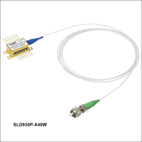 Zoom
ZoomThese SLDs are designed to be used in OCT imaging applications. They have a low gain ripple no larger than 0.3 dB (RMS) and a typical ripple value 0.06 dB (RMS). More information on Thorlabs' SLDs for OCT systems can be found here. Note that the bandwidth will decrease as the current is decreased; bandwidth specifications below are specified at the operating current.
| Item #a | SLD930x-A40W | ||||
|---|---|---|---|---|---|
| Parameter | Min | Typ. | Max | ||
| Operating Current | - | - | 800 mA | ||
| Center Wavelength (CWL)b | 915 nm | 930 nm | 945 nm | ||
| Spectral Shape | Flat Top | ||||
| ASE Powerc,d | 36 mW | 40 mW | - | ||
| Optical 3 dB Bandwidthc | 40 nm | 45 nm | - | ||
| RMS Gain Ripplec,e | - | 0.06 dB | 0.3 dB | ||
| Fiber Type | 780HP (SM) PM780-HP (PM)f |
||||
| Performance Graphs (Click Icons for Plots) | |||||
| Output Spectrum |
|
||||
| LIV Plot |
|
||||
| Gain Ripplee |
|
||||

 Zoom
ZoomIn order to support OCT imaging applications, these SLDs are designed with a low gain ripple no higher than 0.2 dB (RMS) and a typical ripple value of 0.03 dB (RMS). More information on Thorlabs' SLDs for OCT systems can be found here. Note that the bandwidth will decrease as the current is decreased; bandwidth specifications below are specified at the operating current.
| Item #a | SLD970x-A40W | ||
|---|---|---|---|
| Parameter | Min | Typ. | Max |
| Operating Current | - | 1000 mA | 1010 mA |
| Center Wavelength (CWL)b | 945 nm | 970 nm | 995 nm |
| Spectral Shape | Flat Top | ||
| ASE Powerc,d | 35 mW | 40 mW | - |
| Optical 3 dB Bandwidthc,e | 40 nm | 50 nm | - |
| RMS Gain Ripplec,f | - | 0.03 dB | 0.2 dB |
| Fiber Type | HI1060 (SM) PM980-XP (PM)g |
||
| Performance Graphs (Click Icons for Plots) | |||
| Output Spectrum | |||
| LIV Plot | |||
| Gain Ripplef | |||

 Zoom
ZoomThe SLD1050S-A60 is designed to be used in OCT imaging applications. More information on Thorlabs' SLDs for OCT systems can be found here. Note that the bandwidth will decrease as the current is decreased; bandwidth specifications below are specified at the operating current.
| Item #a | SLD1050S | SLD1050P | SLD1050S-A60 | SLD1050P-A60 | ||||||||
|---|---|---|---|---|---|---|---|---|---|---|---|---|
| Parameter | Min | Typ. | Max | Min | Typ. | Max | Min | Typ. | Max | Min | Typ. | Max |
| Operating Current | - | - | 300 mA | - | - | 300 mA | - | - | 1010 mA | - | - | 1010 mA |
| Center Wavelength (CWL)b | 1030 nm | 1050 nm | 1070 nm | 1030 nm | 1050 nm | 1070 nm | 1025 nm | 1050 nm | 1075 nm | 1025 nm | 1050 nm | 1075 nm |
| Spectral Shape | Near Gaussian | Near Gaussian | Flat Top | Flat Top | ||||||||
| ASE Powerc,d | 6 mW | 8 mW | - | 6 mW | 8 mW | - | 55 mW | 60 mW | - | 55 mW | 60 mW | - |
| Optical 3 dB Bandwidthc,e | 40 nm | 50 nm | - | 40 nm | 50 nm | - | 60 nm | 70 nm | - | 60 nm | 70 nm | - |
| Optical 20 dB Bandwidthc | - | - | - | - | - | - | - | 100 nm | - | - | - | - |
| RMS Gain Ripplec,f | - | 0.1 dB | 0.25 dB | - | 0.1 dB | 0.25 dB | - | 0.03 dB | 0.2 dB | - | 0.06 dB | 0.3 dB |
| Fiber Type | HI1060 | PM980-XPg | HI1060 | PM980-XPg | ||||||||
| Performance Graphs (Click Icons for Plots) | ||||||||||||
| Output Spectrum | ||||||||||||
| LIV Plot | ||||||||||||
| Gain Ripplef | - | - | ||||||||||

 Zoom
ZoomThese SLDs are designed to be used for OCT imaging, sensing, linear and non-linear spectroscopy applications. They have a low gain ripple no larger than 0.35 dB (RMS) and a typical ripple of 0.05 dB (RMS). They are packaged with an integrated TEC and thermistor for temperature control, as well as an optical isolator that provides 50 dB of isolation for enhanced optical stability. More information on Thorlabs' SLDs for OCT systems can be found here. Note that the bandwidth will decrease as the current is decreased; bandwidth specifications below are specified at the operating current.
| Item #a | SLD1220x | ||||
|---|---|---|---|---|---|
| Parameter | Min | Typ. | Max | ||
| Operating Current | - | 400 mA | 450 mA | ||
| Center Wavelength (CWL)b | 1205 nm | 1220 nm | 1235 nm | ||
| Spectral Shape | Flat Top | ||||
| ASE Powerc,d | 4 mW | 5 mW | - | ||
| Optical 3 dB Bandwidthc,e | 85 nm | 90 nm | - | ||
| RMS Gain Ripplec,f | - | 0.05 dB | 0.35 dB | ||
| Fiber Type | HI1060 (SM) Corning® PM13-U40A (PM) |
||||
| Integrated Optical Isolator | |||||
| Isolation | - | 50 dB | - | ||
| Performance Graphs (Click Icons for Plots) | |||||
| Output Spectrum |
|
||||
| LIV Plot |
|
||||

 Zoom
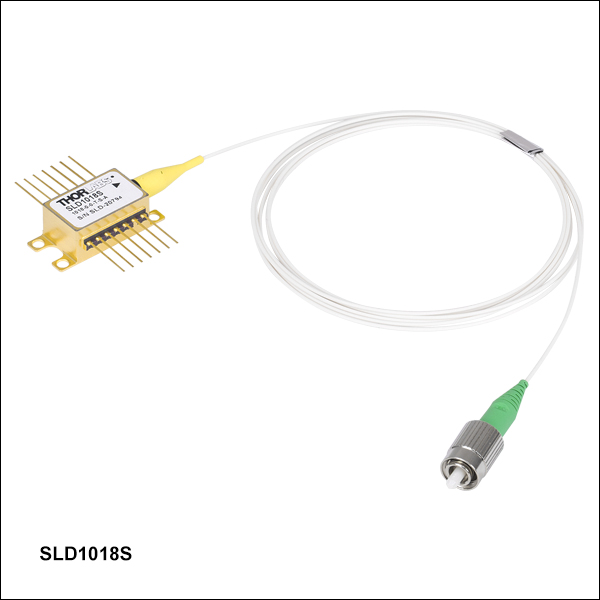
ZoomThe SLD1021S and SLD1310x are designed to be used in OCT imaging applications. More information on Thorlabs' SLDs for OCT systems can be found here. Note that the bandwidth will decrease as the current is decreased; bandwidth specifications below are specified at the operating current. A dual-stage optical isolator is integrated into the SLD1310 and SLD1310P providing a typical of 50 dB optical isolation.
| Item #a | SLD1021S | SLD1018x | SLD1310 | SLD1310P | ||||||||
|---|---|---|---|---|---|---|---|---|---|---|---|---|
| Parameter | Min | Typ. | Max | Min | Typ. | Max | Min | Typ. | Max | Min | Typ. | Max |
| Operating Current | - | 700 mA | 900 mA | - | 600 mA | 800 mA | - | 900 mA | 1000 mA | - | 900 mA | 1000 mA |
| Center Wavelength (CWL)b | 1290 nm | - | 1330 nm | 1290 nm | - | 1330 nm | 1300 nm | 1315 nm | 1330 nm | 1300 nm | 1315 nm | 1330 nm |
| Spectral Shape | Near Gaussian | Near Gaussian | Flat Top | Flat Top | ||||||||
| ASE Powerc,d | 10 mW | 12.5 mW | - | 22 mW | 30 mW | - | 22 mW | 30 mW | - | 22 mW | 30 mW | - |
| Optical 3 dB Bandwidthc,d,e | 80 nm | 85 nm | - | 40 nm | 45 nm | - | 75 nm | 90 nm | - | 75 nm | 90 nm | - |
| RMS Gain Ripplec,f | - | - | 0.35 dB | - | 0.1 dB | 0.35 dB | - | 0.12 dB | 0.3 dB | - | 0.12 dB | 0.3 dB |
| Polarization Extinction Ratio (PER) | - | - | - | - | - | - | - | - | - | - | 23 dB | - |
| Fiber Type | SMF-28e+ | SMF-28e+ (SM) Corning® PM 13-U40A (PM)g |
SMF-28e | Corning PM13-U40Ag | ||||||||
| Benchtop Version | S5FC1021S | S5FC1018S (SM) S5FC1018P (PM) |
- | - | ||||||||
| Integrated Optical Isolator | ||||||||||||
| Isolation | N/Ah | N/Ah | - | 50 dB | - | - | 50 dB | - | ||||
| Performance Plots (Click Icons for Plots) | ||||||||||||
| Output Spectrum | ||||||||||||
| LIV Plot | ||||||||||||
| Gain Ripplef | - | - | ||||||||||

 Zoom
ZoomThe SLD1325 and SLD1330x SLDs are designed to have broad 3 dB bandwidths of >100 nm or 90 nm (typical) respectively, for improved resolution when used in Spectral Domain Optical Coherence Tomography (SD-OCT) systems. These SLDs are packaged with an integrated TEC and thermistor for temperature control, as well as an optical isolator for enhanced optical stability. The isolator in the SLD1325 SLD provides 30 dB minimum of isolation while the isolators in the SLD1330 and SLD1330P SLDs provide 50 dB of isolation. More information on Thorlabs' SLDs for OCT systems can be found here. Note that the bandwidth will decrease as the current is decreased; bandwidth specifications below are specified at the operating current.
| Item #a | SLD1325 | SLD1330 | SLD1330P | ||||||
|---|---|---|---|---|---|---|---|---|---|
| Parameter | Min | Typ. | Max | Min | Typ. | Max | Min | Typ. | Max |
| Operating Current | - | - | 780 mA | - | 1250 mA | 1300 mA | - | 1250 mA | 1300 mA |
| Center Wavelength (CWL)b | - | 1325 nm | - | 1310 nm | 1325 nm | 1340 nm | 1310 nm | 1325 nm | 1340 nm |
| Spectral Shape | Flat Top | Flat Top | Flat Top | ||||||
| ASE Powerc,d | 10 mW | - | - | 35 mW | 40 mW | - | 35 mW | 40 mW | - |
| Optical 3 dB Bandwidthc,d,e | 100 nm | - | - | 80 nm | 90 nm | - | 80 nm | 90 nm | - |
| RMS Gain Ripplec,f | - | 0.1 dB | 0.3 dB | - | 0.1 dB | 0.3 dB | |||
| Polarization Extinction Ratio (PER) | - | - | - | - | - | - | - | 23 dB | - |
| Fiber Type | SMF-28e | SMF-28e | Corning® PM13-U40Ag | ||||||
| Integrated Optical Isolator | |||||||||
| Isolation | 30 dB | - | - | - | 50 dB | - | - | 50 dB | - |
| Performance Graphs (Click Icons for Plots) | |||||||||
| Output Spectrum | |||||||||
| LIV Plot | |||||||||
| Gain Ripplef | - | ||||||||

 Zoom
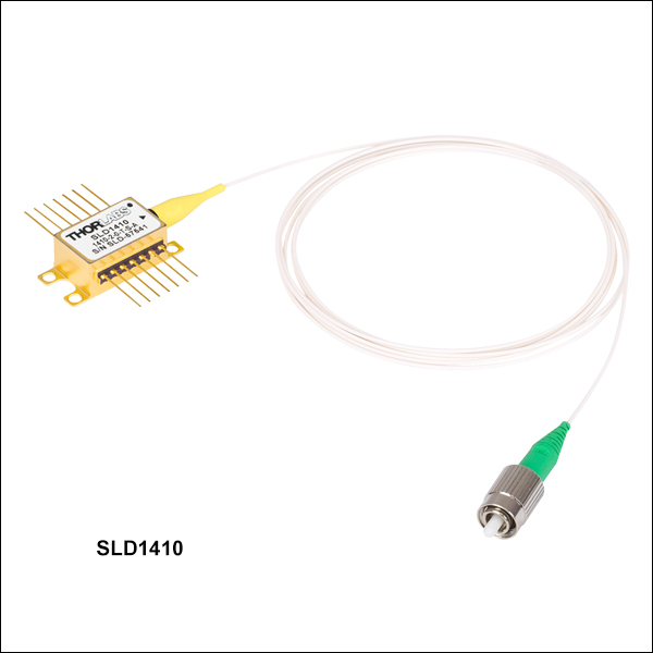
ZoomThese SLDs are designed to be used in OCT imaging applications. They have a low gain ripple no larger than 0.6 dB (RMS) and a typical ripple value 0.2 dB (RMS). They are packaged with an integrated TEC and thermistor for temperature control, as well as an optical isolator which provides 30 dB of isolation for enhanced optical stability. More information on Thorlabs' SLDs for OCT systems can be found here. Note that the bandwidth will decrease as the current is decreased; bandwidth specifications below are specified at the operating current.
| Item #a | SLD1410x | ||||
|---|---|---|---|---|---|
| Parameter | Min | Typ. | Max | ||
| Operating Current | - | 600 mA | 700 mA | ||
| Center Wavelength (CWL)b | 1385 nm | 1400 nm | 1415 nm | ||
| Spectral Shape | Near Gaussian | ||||
| ASE Powerc,d | 4 mW | 5 mW | - | ||
| Optical 3 dB Bandwidthc,e | 90 nm | 98 nm | - | ||
| RMS Gain Ripplec,f | - | 0.2 dB | 0.6 dB | ||
| Fiber Type | SMF-28e (SM) Corning® PM13-U40A (PM) |
||||
| Integrated Optical Isolator | |||||
| Isolation | - | 30 dB | - | ||
| Performance Graphs (Click Icons for Plots) | |||||
| Output Spectrum |
|
||||
| LIV Plot |
|
||||
| Gain Ripplee |
|
||||

 Zoom
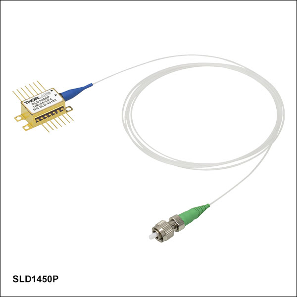
ZoomThese SLDs are designed to be used in OCT imaging applications. They have a low gain ripple no larger than 0.35 dB (RMS) and a typical ripple value 0.06 dB (RMS). More information on Thorlabs' SLDs for OCT systems can be found here. Note that the bandwidth will decrease as the current is decreased; bandwidth specifications below are specified at the operating current.
| Item #a | SLD1450x | ||||
|---|---|---|---|---|---|
| Parameter | Min | Typ. | Max | ||
| Operating Current | - | 500 mA | 600 mA | ||
| Center Wavelength (CWL)b | 1435 nm | 1450 nm | 1465 nm | ||
| Spectral Shape | Near Gaussian | ||||
| ASE Powerc,d | 23 mW | 25 mW | - | ||
| Optical 3 dB Bandwidthc | 50 nm | 54 nm | - | ||
| RMS Gain Ripplec,e | - | 0.06 dB | 0.35 dB | ||
| Fiber Type | SMF-28e (SM) Corning® PM15-U40A (PM) |
||||
| Performance Graphs (Click Icons for Plots) | |||||
| Output Spectrum |
|
||||
| LIV Plot |
|
||||
| Gain Ripplee |
|
||||

 Zoom
ZoomNote that the bandwidth will decrease as the current is decreased; bandwidth specifications below are specified at the operating current.
| Item #a | SLD1550x-A1 | SLD1550x-A2 | SLD1005S | SLD1550x-A40 | ||||||||
|---|---|---|---|---|---|---|---|---|---|---|---|---|
| Parameter | Min | Typ. | Max | Min | Typ. | Max | Min | Typ. | Max | Min | Typ. | Max |
| Operating Current | - | 450 mA | 600 mA | - | 550 mA | 600 mA | - | 600 mA | 800 mA | - | 750 mA | 900 mA |
| Center Wavelength (CWL)b | 1520 nm | 1550 nm | 1580 nm | 1520 nm | 1550 nm | 1580 nm | 1530 nm | 1550 nm | 1570 nm | 1530 nm | 1550 nm | 1570 nm |
| Spectral Shape | Near Gaussian | Near Gaussian | Near Gaussian | Near Gaussian | ||||||||
| ASE Powerc,d | 0.75 mW | 1.0 mW | - | 2.0 mW | 2.5 mW | - | 20 mW | 22 mW | - | 35 mW | 40 mW | - |
| Optical 3 dB Bandwidthc | 90 nm | 110 nm | - | 85 nm | 90 nm | - | 45 nm | 50 nm | - | 30 nm | 33 nm | - |
| RMS Gain Ripplec,e | - | - | 0.1 dB | - | - | 0.25 dB | - | 0.2 dB | 0.35 dB | - | 0.2 dB | 0.35 dB |
| Fiber Type | SMF-28e+ (SM) Corning® PM 15-U40A (PM)f |
SMF-28e+ | SMF-28e+ (SM) Corning PM 15-U40A (PM)f |
|||||||||
| Benchtop Version | N/A | S5FC1550S-A2 (SM) S5FC1550P-A2 (PM) |
S5FC1005S | N/A | ||||||||
| Performance Plots (Click Icon for Plot) | ||||||||||||
| Output Spectrum | ||||||||||||
| LIV Plot | ||||||||||||

 Zoom
ZoomThese SLDs are designed to be used in OCT imaging applications. They have a low gain ripple no larger than 0.5 dB (RMS) and a typical ripple value 0.2 dB (RMS). More information on Thorlabs' SLDs for OCT systems can be found here. Note that the bandwidth will decrease as the current is decreased; bandwidth specifications below are specified at the operating current.
| Item #a | SLD1610x | ||||
|---|---|---|---|---|---|
| Parameter | Min | Typ. | Max | ||
| Operating Current | - | 800 mA | 900 mA | ||
| Center Wavelength (CWL)b | 1590 nm | 1610 nm | 1630 nm | ||
| Spectral Shape | Near Gaussian | ||||
| ASE Powerc,d | 22 mW | 27 mW | - | ||
| Optical 3 dB Bandwidthc | 50 nm | 57 nm | - | ||
| RMS Gain Ripplec,e | - | 0.2 dB | 0.5 dB | ||
| Fiber Type | SMF-28e (SM) Corning® PM15-U40A (PM) |
||||
| Performance Graphs (Click Icons for Plots) | |||||
| Output Spectrum |
|
||||
| LIV Plot |
|
||||
| Gain Ripplee |
|
||||