 Products Home / Fiber Components / Collimation / Coupling / Fixed Focus Collimation Packages / Fixed Focus Collimation Packages: FC/APC Connectors
Fixed Focus Collimation Packages: FC/APC Connectors
- Mates with FC/APC Connectors
- Simplifies Collimation of Output from Single Mode Fiber
- Collimated Beam Diameters Ranging from 0.63 mm to 4.05 mm
- Models Aligned at 13 Key Wavelengths from 405 nm to 4.55 µm
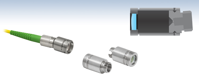
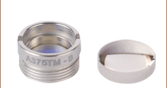
F240APC-A
543 nm, Focal Length: 7.86 mm
Shown with Patch Cable
F220APC-1064
1064 nm, Focal Length: 11.17 mm
Back
Front
Fixed Focus Collimators Contain
One Factory-Aligned Aspheric Lens


Please Wait

Click for Details
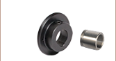
KAD11F Kinematic Tip/Tilt Adapter Used to Mount a Fiber Collimator in
an LM1XY Translation Mount
Features
- Fiber Collimators with FC/APC Connectors (2.2 mm Wide Key) for Single Mode Patch Cables
- Aligned at Wavelengths from 405 nm to 4.55 µm (See Table to the Right)
- Collimated Beam Diameters from 0.63 mm to 4.05 mm Depending on Wavelength
- Each Collimation Package is Factory Aligned
- Simplifies Fiber-Coupled Detection Systems
- Non-Magnetic Stainless Steel Housing
- Compatible with Narrow and Wide Key FC/APC Connectors
- Custom Options, Including Custom Alignment Wavelengths, Available by Contacting Tech Support
These fiber collimation packages are pre-aligned to collimate light from an FC/APC-terminated fiber with diffraction-limited performance. Because these fiber collimators have no movable parts, they are compact and easy to integrate into an existing setup. Due to chromatic aberration, the effective focal length (EFL) of the aspheric lens is wavelength dependent. The design wavelength indicates the wavelength of ideal beam divergence (see the Divergence Plots and Calculations tabs for more information). Collimation packages at select design wavelengths are available with different collimated beam diameters. Select a wavelength from the quick links table to the right for details.
The aspheric lens is factory aligned for collimation at the design wavelength when connected to its specified single mode fiber patch cable. In addition, the aspheric lens has an AR coating on both sides that minimizes surface reflections (see the AR Coating Plots tab). For some applications they may also be used at other wavelengths within the AR coating range; please refer to the theoretical divergence plot for each collimator to determine if it is appropriate for your application. The operating temperature range for these collimators is -40 °C to 93 °C. Please note that these collimation packages are not vacuum compatible. Collimation packages with custom alignment wavelengths, operating temperature ranges, or vacuum compatibility are available by contacting Tech Support.
These fiber collimators are intended for use with single mode fiber patch cables. For improved performance, we recommend using these collimators with our AR-coated single mode fiber optic patch cables. These cables feature an antireflective coating on one fiber end for increased transmission and improved return loss at the fiber-to-free-space interface. Please note performance specifications are guaranteed only when used with single mode fiber.
To mount these fiber collimation packages, we recommend using our collimator mounting adapters, including our kinematic collimator mounting adapters that provide pitch and yaw adjustment. In addition to Ø1/2" and Ø1" unthreaded versions, options are available with external SM05 (0.535"-40), RMS (0.800"-36), or SM1 (1.035"-40) threading. The collimation packages with external M12 x 0.5 threading can be mounted directly into our cage plate CP1M12(/M) to be integrated into our 30 mm cage systems.
Mid-IR Collimators
For our collimators with an alignment wavelength of 3.45 µm and 4.55 µm, we recommend using our angle-polished fluoride fiber patch cables; these collimators include a tightly toleranced ceramic sleeve to protect the fluoride fiber tip during insertion and improve pointing stability. Although these collimators are factory aligned for a specific wavelength, they have low divergence angles over a broad range of wavelengths. Therefore, they may be used at other wavelengths within the AR coating range. Please refer to the theoretical divergence plot for each collimator to determine if it is appropriate for your application.
Alternatives
We also offer a line of adjustable collimation packages called FiberPorts that are well suited for a wide range of wavelengths. These are ideal solutions for adjustable, compact fiber couplers. For other collimation and coupling options, please see our Collimator Guide tab or contact Tech Support.
| Coating Information | |||||||
|---|---|---|---|---|---|---|---|
| Coating Designation | 405 | Aa | Ba | 1064 | Ca | D | E |
| Coating Range |
395 - 415 nm | 350 - 700 nm or 400 - 600 nm |
600 - 1050 nm or 650 - 1050 nm |
1050 - 1075 nm | 1050 - 1620 nm or 1050 - 1700 nm |
1.8 - 3.0 µm | 3 - 5 µm |
| Reflectance | <0.25% @ 405 nm | Ravg < 0.5% within Coating Range |
Ravg < 0.5% within Coating Range |
<0.25% @ 1064 nm | Ravg < 0.5% within Coating Range |
Ravg < 1.0% within Coating Range |
Ravg < 1.0% within Coating Range |
| θ | Divergence Angle |
| D | Mode-Field Diameter (MFD) |
| f | Focal Length of Collimator |
The divergence angle (in Degrees) ,
,
where D and f must be in the same units.
Divergence Angle Comparison
The divergence angle can be estimated using the formula shown to the right, given that the light emerging from the fiber has a Gaussian intensity profile. This formula works well for single mode fibers but will underestimate the divergence angle for multimode fibers where the light emerging from the fiber has a non-Gaussian intensity profile.
Simulations of the theoretical divergence when using one of our standard collimators at wavelengths other than the design wavelength are shown in the graphs below. For example, if you need to collimate 700 nm light from a fiber into a ~1.5 mm diameter beam, the F240APC-780 collimator (represented by the '-780' line in the F240 graph below) can be used but will provide a higher divergence than at its design wavelength of 780 nm. Individual theoretical divergence plots and raw data are also available below for each collimator. Please contact Tech Support to request a collimator aligned at a custom wavelength.

Theoretical Approximation of the Divergence Angle
The beam diameter as a function of propagation distance was simulated for each of our collimators at the design wavelength, assuming input from the design fiber and a Gaussian intensity profile. The design wavelength and fiber are specified in the caption for each graph.
Click to Enlarge
At 405 nm with S405-XP Fiber
Click to Enlarge
At 532 nm with 460HP Fiber
Click to Enlarge
At 543 nm with 460HP Fiber
Click to Enlarge
At 780 nm with 780HP Fiber
Click to Enlarge
At 850 nm with 780HP Fiber
Click to Enlarge
At 980 nm with SM980-5.8-125 Fiber
Click to Enlarge
At 1064 nm with SM980-5.8-125 Fiber

Click to Enlarge
At 1310 nm with SMF-28-J9 Fiber
Click to Enlarge
At 1550 nm with SMF-28-J9 Fiber
Click to Enlarge
At 2000 nm with SM2000 Fiber
Click to Enlarge
At 3.45 µm with ZrF4 Fiber
Click to Enlarge
At 4.55 µm with InF3 Fiber
Theoretical Approximation of the Divergence Angle
The full-angle beam divergence listed in the specifications tables is the theoretically-calculated value associated with the fiber collimator. This divergence angle is easy to approximate theoretically using the formula below as long as the light emerging from the fiber has a Gaussian intensity profile. Consequently, the formula works well for single mode fibers, but it will underestimate the divergence angle for multimode (MM) fibers since the light emerging from a multimode fiber has a non-Gaussian intensity profile.
The Full Divergence Angle (in degrees) is given by
where MFD is the mode field diameter and f is the focal length of the collimator. (Note: MFD and f must have the same units in this equation).
Example:
When the F220FC-A collimator (f ≈ 11.0 mm; not exact since the design wavelength is 543 nm) is used to collimate 515 nm light emerging from a 460HP fiber (MFD = 3.5 µm), the divergence angle is approximately given by
θ ≈ (0.0035 mm / 11.0 mm) x (180 / pi) = 0.018°.
When the beam divergence angle was measured for the F220FC-A collimator, a 460HP fiber was used with 543 nm light. The result was a divergence angle of 0.018°.
Theoretical Approximation of the Output Beam Diameter
The output beam diameter can be approximated from
where λ is the wavelength of light being used, MFD is the mode field diameter, and f is the focal length of the collimator. (Note: MFD and f must have the same units in this equation).
Example:
When the F240FC-1550 collimator (f = 8.18 mm) is used with the P1-SMF28E-FC-1 patch cable (MFD = 10.4 µm) and 1550 nm light, the output beam diameter is
d ≈ (4)(0.00155 mm)[8.18 mm / (pi · 0.0104 mm)] = 1.55 mm.
Theoretical Approximation of the Maximum Waist Distance
The maximum waist distance, which is the furthest distance from the lens the waist can be located in order to maintain collimation, may be approximated by
where f is the focal length of the collimator, λ is the wavelength of light used, and MFD is the mode field diameter. (Note: MFD and f must have the same units in this equation).
Example:
When the F220FC-532 collimator (f = 10.9 mm) is used with the P1-460B-FC-1 patch cable (MFD ≈ 4.0 µm; calculated approximate value) and 532 nm light, then the maximum waist distance is approximately
zmax ≈ 10.9 mm + [2 · (10.9 mm)2 · 0.000532 mm] / [pi · (0.004 mm)2] = 2526 mm.

Insights into Best Lab Practices
Scroll down to read about some practices we follow when setting up lab equipment.
- Align Fiber Collimators to Create Free Space Between Fibers
- Fiber Collimators: Tip for Mounting with Adapters
Click here for more insights into lab practices and equipment.
Align Fiber Collimators to Create Free Space Between Fibers
Two collimators, inserted into a fiber optic setup, provide free-space access to the beam. The first collimator accepts the highly diverging light from the first fiber and outputs a free-space beam, which propagates with an approximately constant diameter to the second collimator. The second collimator accepts the free-space beam and couples that light into the second fiber. Some collimation packages, including the pair used in this demonstration, are designed for use with optical fibers and mate directly to fiber connectors.
Ideally, 100% of the light emitted by the first fiber would be coupled into the second fiber, but some light will always be lost due to reflections, scattering, absorption, and misalignment. Misalignment, typically the largest source of loss, can be minimized using the alignment and stabilization techniques described in this video.
In this demonstration, the first fiber is single mode. The optical power incident on the second collimator, as well as the power output by the second fiber, are measured. When the second fiber is multimode with a 50 µm diameter core, alignment resulted in 91% of the power incident on the second collimator being measured at the fiber output. This value was 86% when the second fiber is single mode. Some differences in collimator designs, and their effects on the characteristics of the collimated beams, are also discussed.
If you would like more information about tips, tricks, and other methods we often use in the lab, we recommend our other Video Insights. In addition, our webinars provide practical and theoretical introductions to our different products.
| Products Featured During Demonstration | ||||
|---|---|---|---|---|
| Fiber-Coupled Laser | Kinematic Mounts | Fiber Adapter Cap (for Power Sensor) |
Single Mode Patch Cable (FC/PC) | Fiber Cable Storage Reels |
| Triplet Fiber Optic Collimators | Power Sensor | Power Meter | Hybrid Single Mode Patch Cable | 2" Posts |
| Adapter (Mount-to-Collimator) |
SM1 Thread Adapter (for Power Sensor) |
Fiber Connector Cleaner | Step-Index Multimode Patch Cable | Ø1/2" Post Holders |
Date of Last Edit: April 21, 2021
Fiber Collimators: Tip for Mounting with Adapters
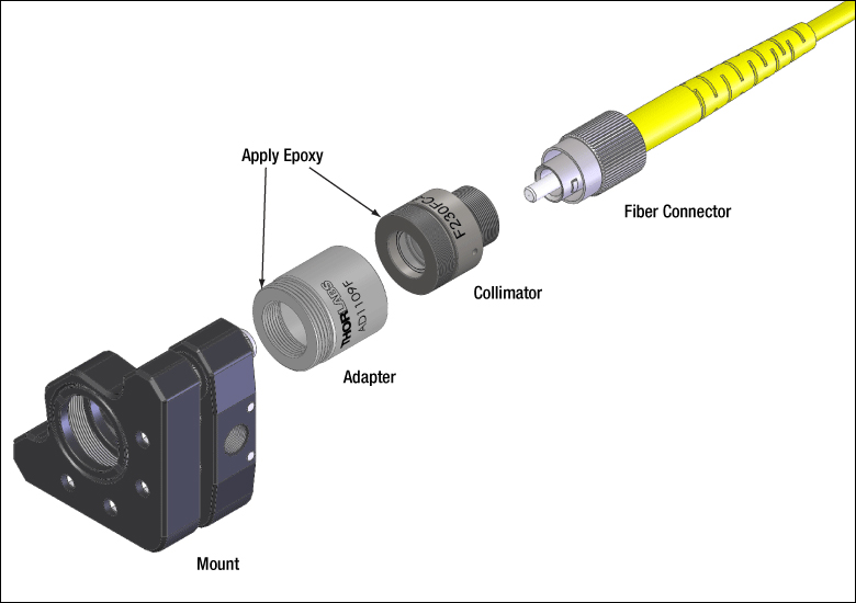
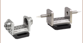
Click to Enlarge
Figure 1: The components shown above are joined using threaded interfaces. Since unscrewing the fiber connector could unintentionally loosen connections between the other components, Thorlabs suggests applying epoxy to the other two interfaces to immobilize them.
Fiber collimators are often used to introduce light into an optical setup from a fiber coupled source. Thorlabs offers a variety of fiber collimator packages, some only provide a smooth barrel (like the triplet collimators) and others have a metric thread at the end of the barrel (like the asphere collimators).
For both packages, Thorlabs typically suggests the use of an adapter with a nylon tipped set screw that holds the barrel against a two line contact.
Adapters for the external thread are available (AD1109F) that allow the user to thread the fiber collimator into a mount.
However, the use of these adapters results in a stack up of threaded interfaces (threaded fiber connector, threaded collimator, and threaded adapter). As a result, it is possible that unscrewing the fiber connector could inadvertently loosen another thread interface and create an unknown source of instability in the setup.
For this reason, Thorlabs suggests epoxying the threaded fiber collimators into the threaded mounts if that mounting mechanism is preferred.
Figure 1 indicates the assembly order and places to apply the epoxy.
Date of Last Edit: Dec. 4, 2019
| Posted Comments: | |
Roberto Hinojosa
(posted 2024-07-11 16:34:08.027) Hello, Our team is interested in buy a couple of focus collimators but we are confused with the NA (numerical aperture) and the MFD. In Calculations you have on Theoretical Approximation of the Divergence Angle:
When the F240FC-1550 collimator (f = 8.18 mm) is used with the P1-SMF28E-FC-1 patch cable (MFD = 10.4 µm) and 1550 nm light, the output beam diameter is
d ≈ (4)(0.00155 mm)[8.18 mm / (pi · 0.0104 mm)] = 1.55 mm.
From here we could have de NA as NA=sin(a)≈tan(a)=d/f, were
the NA must be NA=1.55mm/8.18mm=0.18
But on the information of the P1-SMF28E-FC-1 patch cable you said that NA=0.14. Our question is, we are computed something wrong? Or your data is wrong ? or, we are missing something? Thank you. 施 议焕
(posted 2023-08-02 22:58:15.96) 请问,我们对这个产品有几个问题
1. 这个产品如果反向使用的话是否可以作为一个聚焦透镜使用,用于将空间光聚焦到光纤上?
2. 有这个产品全部波段的增透膜曲线的数据吗?我们希望获得980nm激光对这个产品的透射率
3.或者你们有这个产品未镀膜片的版本吗?希望对2.8 um和0.98 um的激光进行聚焦 cdolbashian
(posted 2023-08-04 11:24:59.0) 1. Can this product be used as a focusing lens if used in reverse to focus spatial light onto an optical fiber?
2. Do you have the data of AR coating curves for all bands of this product? We hope to obtain the transmittance of 980nm laser to this product
3. Or do you have an uncoated version of this product? Want to focus 2.8 um and 0.98 um laser"
1. Indeed this component can take a collimated input and focus the light to a fiber.
2. We have sent you additional, extended, data
3. We have reached out to you to discuss this. user
(posted 2023-04-05 20:19:08.69) Dear Sir/Madam,
We have F230APC-1310 collimators and I want to create free space with these collimators. The distance between collimators is 12.5 cm and light source is BOA1130-P. Unfortunately, I cannot exceed 50% coupling efficiency. For example, My total power is 9.5 mW. I cannot exceed 4.2 mW.
In addition, the back reflection from receiver collimator, is clearly seen near the top of the transmitter collimator's aspheric lens. I got the highest power with this setup. When I try to align back reflection, I get nothing. What is my problem and how can I solve this? cdolbashian
(posted 2023-04-26 09:27:31.0) Thank you for reaching out to us with this inquiry. Before I was able to post this, you and I exchanged some emails, and it seems like the inclusion of appropriate kinematic control assisted you in achieving ~80% coupling. Cristian Tong
(posted 2023-01-04 05:50:07.073) Hello, Can the F260APC-780 collimator be used to couple a free-space beam into the fiber? and, Can this collimator adapted with PM fibers?
Thank you cdolbashian
(posted 2023-01-10 02:27:31.0) Thank you for reaching out to us with this inquiry! These can be used to couple a free space beam into the fiber though since everything is fixed, you may have trouble getting greater than 50% coupling efficiency. While you can use it with a PM fiber, you might not have well-reproducible results with regards to alignment of one of the polarization axes, as we use wide-key adapters on our fiber collimators for ease of use with any FC-style fiber. Arun Jana
(posted 2022-12-10 15:21:47.333) Dear Sir/Madam,
is this output from single-mode polarization maintaining fiber?
looking forward....
Thanks. cdolbashian
(posted 2022-12-15 01:48:28.0) Thank you for contacting us with this inquiry. These collimators are housings for lenses which are nominally isotropic materials. As such we would assume there would be no change of the polarization state while passing through. Emirhan Tosun
(posted 2022-11-30 22:03:42.45) Dear Sir/Madam
I have products with code F280APC-C , AC254-030-C-ML. Can I learn the damage threshold values?
Thanks in advance. Best rigards.
Emirhan Tosun jgreschler
(posted 2022-12-06 01:27:59.0) Thank you for reaching out to Thorlabs. Unfortunately we do not currently have a damage threshold spec for that item. user
(posted 2022-06-24 21:31:54.617) I would like to use F240APC-C with POLARIS-K05T6, which adapter should I use?
Thanks in advance, jdelia
(posted 2022-06-30 04:31:21.0) Thank you for contacting Thorlabs. I have contacted you directly regarding your application. Jan Fait
(posted 2021-11-04 04:27:03.92) Please, is the collimator F240APC-532 suitable for coupling elliptic beam (532 nm, 1.5 mm x 3.5 mm) to a single mode optical fiber (e.g. P3-460B-FC)? Or is it better to use collimator with short focal length (F110APC-532) to have very small focal spot?
Thanks in advance, Jan YLohia
(posted 2021-12-23 11:24:10.0) The shorter focal length will, by definition, produce a smaller beam size for a gaussian beam when focussed. The main consideration you should be wary of is your NA match with the fiber. You will ideally want your NA_fiber > NA_lens+laser, where the NA of the laser would be D/(2*f), where D is the incoming beam diameter, and f is the focal length.
Depending on your fiber and the beam diameter (semi major axis of elliptical beam) at the lens surface, you should pick the appropriate lens with the smallest focal length to satisfy your coupling needs. Ideally you would want to go for a fiberport coupling solution as it has multiple degrees of freedom, which are necessary to get optimal coupling to an SM fiber, due to their core sizes being on the same order as the beam waist. Phani Kumar
(posted 2021-09-25 20:51:15.293) Kindly clarify if the Thorlabs F260APCA collimator is compatible with Polarization-Maintaining FC/APC Fiber Optic Patch Cables. YLohia
(posted 2021-10-11 02:51:07.0) Thank you for contacting Thorlabs. Yes, our FC/APC fiber collimators, such as the F260APC-A, are compatible with FC/APC fiber patch cables (including PM APC cables). wu chao
(posted 2021-05-17 03:18:06.38) 请问准直器的损伤阈值是多少 YLohia
(posted 2021-05-19 01:34:39.0) Thank you for contacting Thorlabs. An applications engineer from our team in China (techsupport-cn@thorlabs.com) will reach out to you directly. user
(posted 2020-06-18 16:43:08.663) To whomever it may concern,
I am concerned about the beam profile from the collimator. Is there information on the truncation of the beam at the lens? nbayconich
(posted 2020-06-23 02:26:04.0) Thank you for your feedback, our fixed focus collimators should not truncate your beam as long as the numerical aperture of the fiber is less than the NA of the collimation package. It would be best to have more information about your fiber first before suggesting a particular collimation package. I will reach out to you directly to discuss your application. Filippo Piffaretti
(posted 2020-04-22 19:00:34.933) Dear Thorlabs,
In my system (915nm) I do need a fixed APC collimator but with a lens with a focal lens of 2mm as one of your adjustable collimator.
In alternative, can you provide ans adjustable collimator with Focal lens of 2mm and a APC connector! With the current PC I loose more than 30% of the laser beam.
Thanks in advance,
Filippo YLohia
(posted 2020-04-24 08:37:57.0) Hello Filippo, thank you for contacting Thorlabs. We offer the PAF2-2B FiberPort collimator with 2 mm focal length, which can be used with FC/APC connectors. This unit will allow 4.4 degrees worth of adjustment on the lens. Please note that after correcting for the 4 degrees for the tilt from APC, you will only have 0.1 mm worth of travel. I have posted your request for APC fixed collimator options for shorter focal lengths on our internal engineering forum for further consideration as a future product. Leonardo de Melo
(posted 2020-03-18 10:13:06.763) I see the transmission listed for the C20APC-C collimator listed, but not for the F280APC-C or the TC18APC-1064. Can you please provide those? YLohia
(posted 2020-03-18 10:40:28.0) Thank you for contacting Thorlabs. The F280APC-C uses the 354280-C lens and its transmission can be found here : https://www.thorlabs.com/images/popupimages/354280_plt.gif. I will reach out to you directly with information regarding the TC18APC-1064. Vasliliy Voropaev
(posted 2019-12-12 12:24:51.21) Hello, could you please write the material and thickness of the lens in the collimator F240APC-1550? We want to calculate ultrashort pulse broadening in this collimator. YLohia
(posted 2019-12-12 01:11:18.0) Hello, thank you for contacting Thorlabs. The material and thickness of the lens used in the F240APC-1550 can be found here : https://www.thorlabs.com/_sd.cfm?fileName=15681-E0W.pdf&partNumber=A240-C Pierre G
(posted 2019-09-26 11:56:16.037) Hello,
What is the material and/or index@532nm for the lense of the F110APC-532 collimator ?
Thanks. YLohia
(posted 2019-09-26 12:10:54.0) Hello, thank you for contacting Thorlabs. A slightly modified version of our 355110-A lens is used in this collimator and its specs can be found here (https://www.thorlabs.com/_sd.cfm?fileName=TTN021132-E0W.pdf&partNumber=355110-A). The lens is made of D-ZLAF52LA. We also share the Zemax file for the F110APC-532 on its product page, which can be used to set up ray simulations. Jerry Liu
(posted 2019-08-28 18:58:34.56) Dear Madam or Sir, Why is the fiber connection part of the collimator is made slightly tilted? what's the purpose of it? And will it affect the transmission of different linear polarization? YLohia
(posted 2019-08-28 12:44:49.0) Hello, thank you for contacting Thorlabs. This connector has the same basic design as the flat FC/PC connector, but is tilted at 4 degrees such that it can accept an FC/APC fiber end which is polished at an 8 degree angle. This “Angled Physical Contact” (APC) interface prevents light reflected at the fiber-fiber junction from traveling back up the fiber. FC/APC connectors only mate properly with other FC/APC connectors. Mating FC/APC with any other connector results in high insertion loss. These connectors minimize back reflections but have a higher insertion loss than their FC/PC counterparts. Using an APC connectorized fiber with an APC collimator will not cause any additional polarization affects. v.t.tenner
(posted 2018-08-31 10:30:31.257) I measured the divergence and beam profile of a F240APC-532, using 520nm light and a P3-488PM-FC-2 and a WinCamD beam profiler. I find a 5x higher divergence than the specs, and a focus in the beam. I repeated this measurements with a non-pm fiber for 633nm and find comparable results. How large are all the tolerances and how likely it is that a different fiber coupler will give values that are so much out of spec? nbayconich
(posted 2018-09-06 04:59:36.0) Thank you for contacting Thorlabs. My apologies that this collimator did not meet our specifications, this is not typical of these collimators. We can of course take back this unit and replace it. I will contact you directly with more information. danielpwhite1993.dw
(posted 2018-06-25 15:07:46.49) Can I use the same F240APC-532 to collimate 405nm and 532nm from SM400 fibre? YLohia
(posted 2018-06-25 10:10:32.0) You could use the same collimator, however, the level of collimation and beam diameters for the two wavelengths will be different as can be seen here: https://www.thorlabs.com/images/TabImages/Divergence_F240-532_780.gif. For a truly achromatic performance, we recommend using reflective collimators that can be found on this page: https://www.thorlabs.com/newgrouppage9.cfm?objectgroup_id=4093. jchg2758
(posted 2017-10-16 18:44:22.977) Can I used this receptacle collimator to PM fiber? It is denoted as for single mode fiber but I wanna know how it is designed for single mode (only?). tfrisch
(posted 2017-10-17 04:06:24.0) Hello, thank you for contacting Thorlabs. You can use these collimators in reverse to couble light into PM fiber as it is also single mode. The input polarization will need to be linear and aligned to the PM axis of the fiber. I will contact you directly to discuss this. andreas.rohrbacher
(posted 2017-02-02 03:28:02.83) Hi. What are the temperature specs (operating and storage) for the F240APC-1064? Could the part be temp-cycled +-30 °C from ambient temperature (25°C) without damage to i.e. the lens? tcampbell
(posted 2017-02-06 12:17:50.0) Response from Tim at Thorlabs: thank you for your feedback. The operating temperature range for these collimators is -40 °C to 93 °C. Yes, the collimators can operate in the range of 25 +/- 30 °C. jeremy.saucourt
(posted 2016-05-26 11:24:35.43) Hi. I have several F220APC-1064 collimators placed on kinematic mounts. I use one to collimate the output of a PM980-XP fiber. Then, I use a second one to inject this collimated beam in another PM980-XP fiber.
Before the second collimator, I measure the beam power to be 12 mW (generated by a 1064 nm laser diode). After it, without connecting the fiber to be injected, I measure a 11.8 mW power meaning that alignment is correct. After inserting a 1m welding-free PM980-XP cable and adjusting kinematic knobs for maximal injection, I can only measure up to 4.1 mW, meaning that a maximum of 35 percents of the energy is injected in the fiber. The two collimators are separated by about 5 centimeters.
Any idea on why I cannot inject up to about 90% of the energy on the fiber ? besembeson
(posted 2016-05-26 03:47:04.0) Response from Bweh at Thorlabs USA: The coarse alignment you did helps to center the collimators roughly. After the fiber is inserted, you need to use the kinematic adjustments (hopefully you have at least one) of the mount (s) that hold the collimators to optimize your coupling efficiency. Remember you are creating a spot of under 10um to couple to the fiber so any small misalignment is critical. mesmail
(posted 2015-03-04 08:30:35.033) Hi. I have bought two F280APC-1550 collimators with two P3-SMF28EAR-2 patch cables. I did FSO setup (50 cm distance) with very good alignment and transmitted 30mW using one collimator. When the path cable is not connected to the receiver collimator, I can see the received beam from the collimator output using a viewing card which means the allignment is good. However, when I connected the patch fiber to the receiver collimator, I get very low (in nW) measured using a power meter. Is this because due to the separation distance? any suggestions? jlow
(posted 2015-03-24 11:34:50.0) Response from Jeremy at Thorlabs: It seems that the 2nd collimator is slightly misaligned. It should be placed on a kinematic mount to optimize the alignment. I will contact you directly to discuss more about this. rolland
(posted 2014-12-01 18:22:58.51) Dear Sir or Madam,
I am interested in the collimator F280APC-B to be used with a ~2 mW SLED output at 670 to 680 nm. For our application, the collimator would be placed in a moderate vacuum, of the order of 10^{-6} mbar.
Is the collimator vacuum compatible in this condition ?
Cheers,
L. Rolland jlow
(posted 2014-12-11 01:33:23.0) Response from Jeremy at Thorlabs: These collimators are not vacuum compatible. We can possibly make a custom version. I will contact you directly too discuss about this. clesch
(posted 2014-06-28 16:24:59.027) Dear Madam or Sir,
I'd like to know if one can cause any harm by connecting one of your SM/PC fibers to one of the "Fixed Focus Collimation Packages: FC/APC Connectors" (e.g. F260APC-B) or - vice versa - connecting a SM/APC fiber to a collimation package of FC/PC (e.g. F240FC-B) standard.
Thanks for your information in advance jlow
(posted 2014-08-05 02:33:01.0) Response from Jeremy at Thorlabs: Mismatching the connector type will cause the beam to hit the lens at an angle and distort the output beam. ako.chijioke
(posted 2013-04-22 18:49:05.82) which is recommended for 633nm, f240APC-A or f240APC-B? The latter is aligned at 633 nm but has AR coating that starts at 650 nm. Thanks tcohen
(posted 2013-04-25 16:32:00.0) Response from Tim at Thorlabs: For your 633nm source, it would be preferable to use the F240APC-B for the best collimation performance. The performance of the coating will still be suitable at this wavelength. I will contact you to continue this discussion. koreancarsg
(posted 2013-03-20 12:44:16.377) am looking for a collimator for Fiber coupled superluminescent diode, 1mW @ 680nm. However found closes available is 633nm. Need advice which collimator is suitable? tcohen
(posted 2013-03-21 16:14:00.0) Response from Tim at Thorlabs: We can custom align these collimators to a desired center wavelength. However, as this has a refractive (aspheric) optic it will have chromatic focal shift over the bandwidth of your superluminescent diode and will therefore have poorer collimation quality as you deviate from your center wavelength. Depending on your performance requirements, this may be acceptable. Alternatively, you could look to use a reflective collimator. I will contact you to discuss your setup further. marshabr
(posted 2012-11-29 11:01:09.31) I purchased 4 of the F240APC-1550 collimators. They appear to be focused incorrectly. The far field spot (8 meters) can be reduced in size by about 1/2 if I loosen the nut and pull the fiber away from the lens. The coupling between two collimators or from one collimator to itself via a mirror can be improved by 2x or more by adjusting the fiber position. I tried several different FC/APC connectors from different manufacturers, with similar results.
Is this a known problem with these collimators?
How do you determine the focus point when assembling these collimators? jlow
(posted 2012-08-09 16:02:00.0) Response from Jeremy at Thorlabs: Thank you for your feedback. I have forwarded this to our engineering group to look into. One possible drawback with the S1TM12 is that there's no hard stop for the collimator to push against and therefore might not be suitable in the long run. shaun.johnstone
(posted 2012-08-08 01:21:25.0) Instead of suggesting the AD12F adapter for the F240APC-780 product, I would suggest using the S1TM12 adapter.
This way your fiber collimator is held nicely by the thread on the end of itself, and not by a grub screw (which is not a repeatable mounting scheme). |
Fiber Collimator Selection Guide
Click on the collimator type or photo to view more information about each type of collimator.
| Type | Description | |
|---|---|---|
| Fixed FC, APC, or SMA Fiber Collimators | 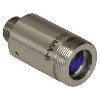 |
These fiber collimation packages are pre-aligned to collimate light from an FC/PC-, FC/APC-, or SMA-terminated fiber. Each collimation package is factory aligned to provide diffraction-limited performance for wavelengths ranging from 405 nm to 4.55 µm. Although it is possible to use the collimator at detuned wavelengths, they will only perform optimally at the design wavelength due to chromatic aberration, which causes the effective focal length of the aspheric lens to have a wavelength dependence. |
| Air-Spaced Doublet, Large Beam Collimators | 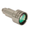 |
For large beam diameters (Ø5.3 - Ø8.5 mm), Thorlabs offers FC/APC, FC/PC, and SMA air-spaced doublet collimators. These collimation packages are pre-aligned at the factory to collimate a laser beam propagating from the tip of an FC or SMA-terminated fiber and provide diffraction-limited performance at the design wavelength. |
| Triplet Collimators |  |
Thorlabs' High Quality Triplet Fiber Collimation packages use air-spaced triplet lenses that offer superior beam quality performance when compared to aspheric lens collimators. The benefits of the low-aberration triplet design include an M2 term closer to 1 (Gaussian), less divergence, and less wavefront error. |
| Achromatic Collimators for Multimode Fiber | 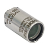 |
Thorlabs' High-NA Achromatic Collimators pair a meniscus lens with an achromatic doublet for high performance across the visible spectrum with low spherical aberration. Designed for use with high-NA multimode fiber, these collimators are ideal for Optogenetics and Fiber Photometry applications. |
| Reflective Collimators | 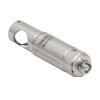 |
Thorlabs' metallic-coated Reflective Collimators are based on a 90° off-axis parabolic mirror. Mirrors, unlike lenses, have a focal length that remains constant over a broad wavelength range. Due to this intrinsic property, a parabolic mirror collimator does not need to be adjusted to accommodate various wavelengths of light, making them ideal for use with polychromatic light. Our reflective collimators are ideal for collimating single mode fiber but are not recommended for coupling into single mode fiber. We also offer a compact version of the protected-silver-coated reflective collimators that is directly compatible with our 16 mm cage system. |
| FiberPorts | 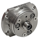 |
These compact, ultra-stable FiberPort micropositioners provide an easy-to-use, stable platform for coupling light into and out of FC/PC, FC/APC, or SMA terminated optical fibers. It can be used with single mode, multimode, or PM fibers and can be mounted onto a post, stage, platform, or laser. The built-in aspheric or achromatic lens is available with five different AR coatings and has five degrees of alignment adjustment (3 translational and 2 pitch). The compact size and long-term alignment stability make the FiberPort an ideal solution for fiber coupling, collimation, or incorporation into OEM systems. |
| Adjustable Fiber Collimators |  |
These collimators are designed to connect onto the end of an FC/PC, FC/APC, or SMA connector and contain an AR-coated aspheric lens. The distance between the aspheric lens and the tip of the fiber can be adjusted to compensate for focal length changes or to recollimate the beam at the wavelength and distance of interest. |
| Achromatic Fiber Collimators with Adjustable Focus | 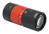 |
Thorlabs' Achromatic Fiber Collimators with Adjustable Focus are designed with an effective focal length (EFL) of 20 mm, 40 mm, or 80 mm, have optical elements broadband AR coated for one of three wavelength ranges, and are available with FC/PC, FC/APC, or SMA905 connectors. A four-element, air-spaced lens design produces superior beam quality (M2 close to 1) and less wavefront error when compared to aspheric lens collimators. These collimators can be used for free-space coupling into a fiber, collimation of output from a fiber, or in pairs for collimator-to-collimator coupling over long distances, which allows the beam to be manipulated prior to entering the second collimator. |
| Zoom Fiber Collimators | 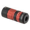 |
These collimators provide a variable focal length between 6 and 18 mm, while maintaining the collimation of the beam. As a result, the size of the beam can be changed without altering the collimation. This universal device saves time previously spent searching for the best suited fixed fiber collimator and has a very broad range of applications. They are offered with FC/PC, FC/APC, or SMA905 connectors with three different antireflection wavelength ranges to choose from. |
| Single Mode Pigtailed Collimators | 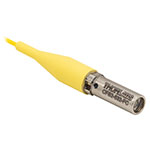 |
Our single mode pigtailed collimators come with one meter of fiber, consist of an AR-coated aspheric lens pre-aligned with respect to a fiber, and are collimated at one of eight wavelengths: 532 nm, 633 nm, 780 nm, 850 nm, 1030 nm, 1064 nm, 1310 nm, or 1550 nm. Although it is possible to use the collimator at any wavelength within the coating range, the coupling loss will increase as the wavelength is detuned from the design wavelength. |
| Polarization Maintaining Pigtailed Collimators | 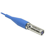 |
Our polarization maintaining pigtailed collimators come with one meter of fiber, consist of an AR-coated aspheric lens pre-aligned with respect to a fiber, and are collimated at one of five wavelengths: 633 nm, 780 nm, 980 nm, 1064 nm, or 1550 nm. Custom wavelengths and connectors are available as well. A line is engraved along the outside of the housing that is parallel to the fast axis. As such, it can be used as a reference when polarized light is launched accordingly. Although it is possible to use the collimator at any wavelength within the coating range, the coupling loss will increase as the wavelength is detuned from the design wavelength. |
| GRIN Fiber Collimators | 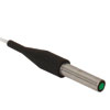 |
Thorlabs offers gradient index (GRIN) fiber collimators that are aligned at a variety of wavelengths from 630 to 1550 nm and have either FC terminated, APC terminated, or unterminated fibers. Our GRIN collimators feature a Ø1.8 mm clear aperture, are AR-coated to ensure low back reflection into the fiber, and are coupled to standard single mode or graded-index multimode fibers. |
| GRIN Lenses |  |
These graded-index (GRIN) lenses are AR coated for applications at 630, 830, 1060, 1300, or 1560 nm that require light to propagate through one fiber, then through a free-space optical system, and finally back into another fiber. They are also useful for coupling light from laser diodes into fibers, coupling the output of a fiber into a detector, or collimating laser light. Our GRIN lenses are designed to be used with our Pigtailed Glass Ferrules and GRIN/Ferrule sleeves. |
| Item # | Alignment Wavelengtha |
Lens AR Coating | Waist Diameterb | Waist Distancec | Full Angle Divergenced | Theoretical Divergence |
NA | Focal Lengthe | Housing Outer Diameterf |
External Threading |
|---|---|---|---|---|---|---|---|---|---|---|
| F671APC-405 | 405 nm | 395 - 415 nm Ravg < 0.25% |
0.63 mm | 3.56 mm | 0.05° +0.01 / -0.00° | Raw Data |
0.60 | 4.02 mm | 11 mm | M11 x 0.5 |
| Item # | Alignment Wavelengtha |
Lens AR Coating | Waist Diameterb | Waist Distancec | Full-Angle Divergenced | Theoretical Divergence |
NA | Focal Lengthe | Housing Outer Diameter |
External Threading |
|---|---|---|---|---|---|---|---|---|---|---|
| F110APC-532 | 532 nm | 350 - 700 nm Ravg < 0.5% |
1.14 mm | 5.85 mm | 0.03 +0.01 / -0.00° |  Raw Data |
0.38 | 6.09 mm | 11 mmf | M11 x 0.5 |
| F240APC-532 | 532 nm | 350 - 700 nm Ravg < 0.5% |
1.48 mm | 6.96 mm | 0.03 +0.01 / -0.00° |  Raw Data |
0.51 | 7.86 mm | 12 mmg | M12 x 0.5 |
| F220APC-532 | 532 nm | 350 - 700 nm Ravg < 0.5% |
2.1 mm | 10.72 mm | 0.02 +0.01 / -0.00° |  Raw Data |
0.25 | 10.90 mm | 11 mmf | M11 x 0.5 |
| Item # | Alignment Wavelengtha |
Lens AR Coating | Waist Diameterb | Waist Distancec | Full-Angle Divergenced | Theoretical Divergence |
NA | Focal Lengthe | Housing Outer Diameter |
External Threading |
|---|---|---|---|---|---|---|---|---|---|---|
| F230APC-A | 543 nm | 350 - 700 nm Ravg < 0.5% |
0.83 mm | 4.02 mm | 0.05 +0.01 / -0.00° |  Raw Data |
0.57 | 4.34 mm | 11 mmg | M11 x 0.5 |
| F240APC-A | 543 nm | 350 - 700 nm Ravg < 0.5% |
1.5 mm | 6.97 mm | 0.027° |  Raw Data |
0.51 | 7.86 mm | 12 mmf | M12 x 0.5 |
| F220APC-A | 543 nm | 350 - 700 nm Ravg < 0.5% |
2.06 mm | 10.74 mm | 0.019 +0.010 / -0.000° |  Raw Data |
0.25 | 10.92 mm | 11 mmg | M11 x 0.5 |
| F260APC-A | 543 nm | 400 - 600 nm Ravg < 0.5% |
2.8 mm | 14.85 mm | 0.014° |  Raw Data |
0.17 | 15.01 mm | 11 mmg | M11 x 0.5 |
| F280APC-A | 543 nm | 400 - 600 nm Ravg < 0.5% |
3.3 mm | 17.40 mm | 0.012° |  Raw Data |
0.15 | 18.07 mm | 11 mmg | M11 x 0.5 |
| Item # | Alignment Wavelengtha |
Lens AR Coating | Waist Diameterb | Waist Distancec | Full-Angle Divergence | Theoretical Divergence |
NA | Focal Lengthd | Housing Outer Diameter |
External Threading |
|---|---|---|---|---|---|---|---|---|---|---|
| F230APC-633 | 633 nm | 350 - 700 nm Ravg < 0.5% |
0.84 mm | 4.07 mm | 0.055 +0.01 / -0.00°e |  Raw Data |
0.56 | 4.46 mm | 11 mmg | M11 x 0.5 |
| F110APC-633 | 633 nm | 350 - 700 nm Ravg < 0.5% |
1.16 mm | 5.93 mm | 0.04 +0.01 / -0.00°f | Raw Data |
0.38 | 6.17 mm | 11 mmg | M11 x 0.5 |
| F240APC-B | 633 nm | 650 - 1050 nm Ravg < 0.5% |
1.5 mm | 6.96 mm | 0.031°f | Raw Data |
0.50 | 7.93 mm | 12 mmh | M12 x 0.5 |
| F220APC-633 | 633 nm | 350 - 700 nm Ravg < 0.5% |
2.06 mm | 10.83 mm | 0.022 +0.01 / -0.00°e |  Raw Data |
0.25 | 11.00 mm | 11 mmg | M11 x 0.5 |
| F260APC-B | 633 nm | 600 - 1050 nm Ravg < 0.5% |
2.8 mm | 14.87 mm | 0.016°f |  Raw Data |
0.16 | 15.15 mm | 11 mmg | M11 x 0.5 |
| F280APC-B | 633 nm | 600 - 1050 nm Ravg < 0.5% |
3.4 mm | 17.52 mm | 0.015°f |  Raw Data |
0.15 | 18.24 mm | 11 mmg | M11 x 0.5 |
| Item # | Alignment Wavelengtha |
Lens AR Coating | Waist Diameterb | Waist Distancec | Full-Angle Divergence | Theoretical Divergence | NA | Focal Lengthd | Housing Outer Diameter |
External Threading |
|---|---|---|---|---|---|---|---|---|---|---|
| F230APC-780 | 780 nm | 650 - 1050 nm Ravg < 0.5% |
0.98 mm | 4.12 mm | 0.06 +0.01 / -0.00°e |  Raw Data |
0.55 | 4.51 mm | 11 mmg | M11 x 0.5 |
| F110APC-780 | 780 nm | 650 - 1050 nm Ravg < 0.5% |
1.36 mm | 6.00 mm | 0.04 +0.01 / -0.00°f |  Raw Data |
0.37 | 6.24 mm | 11 mmg | M11 x 0.5 |
| F240APC-780 | 780 nm | 650 - 1050 nm Ravg < 0.5% |
1.5 mm | 7.09 mm | 0.036°f |  Raw Data |
0.50 | 8.00 mm | 12 mmh | M12 x 0.5 |
| F220APC-780 | 780 nm | 650 - 1050 nm Ravg < 0.5% |
2.1 mm | 10.91 mm | 0.026°f |  Raw Data |
0.26 | 11.07 mm | 11 mmg | M11 x 0.5 |
| F260APC-780 | 780 nm | 650 - 1050 nm Ravg < 0.5% |
3.33 mm | 15.11 mm | 0.02 +0.01 / -0.00°e |  Raw Data |
0.16 | 15.29 mm | 11 mmg | M11 x 0.5 |
| F280APC-780 | 780 nm | 650 - 1050 nm Ravg < 0.5% |
4.00 mm | 17.68 mm | 0.01 +0.01 / -0.00°e |  Raw Data |
0.15 | 18.40 mm | 11 mmg | M11 x 0.5 |
| Item # | Alignment Wavelengtha |
Lens AR Coating | Waist Diameterb | Waist Distancec | Full-Angle Divergence | Theoretical Divergence |
NA | Focal Lengthed | Housing Outer Diameter |
External Threading |
|---|---|---|---|---|---|---|---|---|---|---|
| F230APC-850 | 850 nm | 650 - 1050 nm Ravg < 0.5% |
0.98 mm | 4.13 mm | 0.06 +0.01 / -0.00°e |  Raw Data |
0.49 | 4.53 mm | 11 mmg | M11 x 0.5 |
| F110APC-850 | 850 nm | 650 - 1050 nm Ravg < 0.5% |
1.36 mm | 6.02 mm | 0.05 +0.01 / -0.00°f |  Raw Data |
0.37 | 6.26 mm | 11 mmg | M11 x 0.5 |
| F240FAPC-850 | 850 nm | 650 - 1050 nm Ravg < 0.5% |
1.74 mm | 7.11 mm | 0.04 +0.01 / -0.00°e |  Raw Data |
0.50 | 8.02 mm | 12 mmh | M12 x 0.5 |
| F220APC-850 | 850 nm | 650 - 1050 nm Ravg < 0.5% |
2.41 mm | 10.94 mm | 0.03 +0.01 / -0.00°e |  Raw Data |
0.25 | 11.12 mm | 11 mmg | M11 x 0.5 |
| F260APC-850 | 850 nm | 650 - 1050 nm Ravg < 0.5% |
3.32 mm | 15.15 mm | 0.02 +0.01 / -0.00°e |  Raw Data |
0.16 | 15.33 mm | 11 mmg | M11 x 0.5 |
| F280APC-850 | 850 nm | 650 - 1050 nm Ravg < 0.5% |
3.99 mm | 17.73 mm | 0.02 +0.01 / -0.00°e |  Raw Data |
0.15 | 18.45 mm | 11 mmg | M11 x 0.5 |
| Item # | Alignment Wavelengtha |
Lens AR Coating | Waist Diameterb | Waist Distancec | Full-Angle Divergence | Theoretical Divergence |
NA | Focal Lengthd | Housing Outer Diameter |
External Threading |
|---|---|---|---|---|---|---|---|---|---|---|
| F230APC-980 | 980 nm | 650 - 1050 nm Ravg < 0.5% |
0.98 mm | 4.16 mm | 0.073 +0.01 / -0.00°e |  Raw Data |
0.49 | 4.55 mm | 11 mmg | M11 x 0.5 |
| F110APC-980 | 980 nm | 650 - 1050 nm Ravg < 0.5% |
1.35 mm | 6.05 mm | 0.05 +0.01 / -0.00°f |  Raw Data |
0.37 | 6.29 mm | 11 mmg | M11 x 0.5 |
| F240APC-980 | 980 nm | 600 - 1050 nm Ravg < 0.5% |
1.7 mm | 7.15 mm | 0.04 +0.01 / -0.00°e |  Raw Data |
0.50 | 8.06 mm | 12 mmh | M12 x 0.5 |
| F220APC-980 | 980 nm | 600 - 1050 nm Ravg < 0.5% |
2.4 mm | 10.99 mm | 0.03 +0.01 / -0.00°e |  Raw Data |
0.25 | 11.16 mm | 11 mmg | M11 x 0.5 |
| F260APC-980 | 980 nm | 650 - 1050 nm Ravg < 0.5% |
3.31 mm | 15.22 mm | 0.022 +0.01 / -0.00°e |  Raw Data |
0.16 | 15.39 mm | 11 mmg | M11 x 0.5 |
| F280APC-980 | 980 nm | 600 - 1050 nm Ravg < 0.5% |
4.0 mm | 17.81 mm | 0.02 +0.01 / -0.00°e |  Raw Data |
0.15 | 18.53 mm | 11 mmg | M11 x 0.5 |
| Item # | Alignment Wavelength |
Lens AR Coating | Waist Diameterb | Waist Distancec | Full-Angle Divergence | Theoretical Divergence |
NA | Focal Lengthd | External Threading |
Housing Outer Diameter |
|---|---|---|---|---|---|---|---|---|---|---|
| F230APC-1064 | 1064 nm | 650 - 1050 nm Ravg < 0.5% |
1.00 mm | 4.17 mm | 0.08 +0.01 / -0.00°e |  Raw Data |
0.55 | 4.56 mm | M11 x 0.5g | 11 mm |
| F110APC-1064 | 1064 nm | 1050 - 1700 nm Ravg < 0.5% |
1.38 mm | 6.07 mm | 0.06 +0.01 / -0.00°f |  Raw Data |
0.37 | 6.31 mm | M11 x 0.5g | 11 mm |
| F240APC-1064 | 1064 nm | 650 - 1050 nm Ravg < 0.5% |
1.76 mm | 7.16 mm | 0.04 +0.01 / -0.00°e |  Raw Data |
0.50 | 8.07 mm | M12 x 0.5h | 12 mm |
| F220APC-1064 | 1064 nm | 1050 - 1075 nm Ravg < 0.25% |
2.4 mm | 11.02 mm | 0.032°e |  Raw Data |
0.25 | 11.17 mm | M11 x 0.5g | 11 mm |
| F260APC-1064 | 1064 nm | 650 - 1050 nm Ravg < 0.5% |
3.37 mm | 15.25 mm | 0.02 +0.01 / -0.00°e |  Raw Data |
0.16 | 15.43 mm | M11 x 0.5g | 11 mm |
| F280APC-1064 | 1064 nm | 650 - 1050 nm Ravg < 0.5% |
4.05 mm | 17.86 mm | 0.02 +0.01 / -0.00°e |  Raw Data |
0.15 | 18.60 mm | M11 x 0.5g | 11 mm |
| Item # | Alignment Wavelengtha |
Lens AR Coating | Waist Diameterb | Waist Distancec | Full-Angle Divergence | Theoretical Divergence |
NA | Focal Lengthd | Housing Outer Diameter |
External Threading |
|---|---|---|---|---|---|---|---|---|---|---|
| F230APC-1310 | 1310 nm | 1050 - 1620 nm Ravg < 0.5% |
0.83 mm | 4.20 mm | 0.115 +0.01 / -0.00°e |  Raw Data |
0.54 | 4.59 mm | 11 mmg | M11 x 0.5 |
| F110APC-1310 | 1310 nm | 1050 - 1700 nm Ravg < 0.5% |
1.15 mm | 6.10 mm | 0.08 +0.01 / -0.00°f |  Raw Data |
0.37 | 6.35 mm | 11 mmg | M11 x 0.5 |
| F240APC-C | 1310 nm | 1050 - 1620 nm Ravg < 0.5% |
1.5 mm | 7.21 mm | 0.065°e |  Raw Data |
0.49 | 8.13 mm | 12 mmh | M12 x 0.5 |
| F220APC-1310 | 1310 nm | 1050 - 1620 nm Ravg < 0.5% |
2.04 mm | 11.08 mm | 0.047 +0.01 / -0.00°f |  Raw Data |
0.25 | 11.26 mm | 11 mmg | M11 x 0.5 |
| F260APC-C | 1310 nm | 1050 - 1620 nm Ravg < 0.5% |
2.8 mm | 15.35 mm | 0.034°e |  Raw Data |
0.16 | 15.52 mm | 11 mmg | M11 x 0.5 |
| F280APC-C | 1310 nm | 1050 - 1620 nm Ravg < 0.5% |
3.4 mm | 17.96 mm | 0.028°e |  Raw Data |
0.15 | 18.67 mm | 11 mmg | M11 x 0.5 |
| Item # | Alignment Wavelengtha |
Lens AR Coating | Waist Diameterb | Waist Distancec | Full-Angle Divergence | Theoretical Divergence |
NA | Focal Lengthd | Housing Outer Diameter |
External Threading |
|---|---|---|---|---|---|---|---|---|---|---|
| F230APC-1550 | 1550 nm | 1050 - 1620 nm Ravg < 0.5% |
0.87 mm | 4.21 mm | 0.129 +0.01 / -0.00°e |  Raw Data |
0.54 | 4.61 mm | 11 mmg | M11 x 0.5 |
| F110APC-1550 | 1550 nm | 1050 - 1700 nm Ravg < 0.5% |
1.21 mm | 6.13 mm | 0.09 +0.01 / -0.00°f |  Raw Data |
0.37 | 6.37 mm | 11 mmg | M11 x 0.5 |
| F240APC-1550 | 1550 nm | 1050 - 1620 nm Ravg < 0.5% |
1.6 mm | 7.26 mm | 0.073°f |  Raw Data |
0.49 | 8.18 mm | 12 mmh | M12 x 0.5 |
| F220APC-1550 | 1550 nm | 1050 - 1620 nm Ravg < 0.5% |
2.15 mm | 11.15 mm | 0.053 +0.01 / -0.00°e |  Raw Data |
0.24 | 11.32 mm | 11 mmg | M11 x 0.5 |
| F260APC-1550 | 1550 nm | 1050 - 1620 nmRavg < 0.5% | 3.0 mm | 15.44 mm | 0.038°f |  Raw Data |
0.16 | 15.58 mm | 11 mmg | M11 x 0.5 |
| F280APC-1550 | 1550 nm | 1050 - 1620 nm Ravg < 0.5% |
3.6 mm | 18.07 mm | 0.032°f |  Raw Data |
0.15 | 18.75 mm | 11 mmg | M11 x 0.5 |
| Item # | Alignment Wavelengtha |
Lens AR Coating | Waist Diameterb | Waist Distancec | Full-Angle Divergenced | Theoretical Divergence |
NA | Focal Lengthe | Housing Outer Diameterf |
External Threading |
|---|---|---|---|---|---|---|---|---|---|---|
| F028APC-2000 | 2 µm | 1.8 - 3.0 µm Ravg < 1.0% |
1.2 mm | 5.73 mm | 0.13° +0.01 / -0.00° |  Raw Data |
0.56 | 5.91 mm | 11 mm | M11 x 0.5 |
Although this collimator is factory aligned for a specific wavelength, it has low divergence angles over a broad range of wavelengths. Therefore, it may be used at other wavelengths within the AR coating range. Please refer to the theoretical divergence plot for this collimator to determine if it is appropriate for your application.
| Item # | Alignment Wavelengtha |
Lens AR Coating | Waist Diameterb | Waist Distancec | Full-Angle Divergenced | Theoretical Divergence |
NA | Focal Lengthe | Housing Outer Diameterf |
External Threading |
|---|---|---|---|---|---|---|---|---|---|---|
| F028APC-3450 | 3.45 µm | 3 - 5 µm Ravg < 1.0% |
2.01 mm | 5.77 mm | 0.125 +0.01 / -0.00° |  Raw Data |
0.56 | 5.94 mm | 11 mm | M11 x 0.5 |
Although this collimator is factory aligned for a specific wavelength, it has a low divergence angle over a broad range of wavelengths. Therefore, it may be used at other wavelengths within the AR coating range. Please refer to the theoretical divergence plot for this collimator to determine if it is appropriate for your application.
| Item # | Alignment Wavelengtha |
Lens AR Coating | Waist Diameterb | Waist Distancec | Full-Angle Divergenced | Theoretical Divergence |
NA | Focal Lengthe | Housing Outer Diameterf |
External Threading |
|---|---|---|---|---|---|---|---|---|---|---|
| F028APC-4950 | 4.55 µm | 3 - 5 µm Ravg < 1.0% |
2.16 mm | 5.79 mm | 0.15 +0.05 / -0° |  Raw Data |
0.56 | 5.97 mm | 11 mm | M11 x 0.5 |