 Products Home / Fiber Components / Collimation / Coupling / Adjustable Aspheric Collimators / FC/PC Adjustable Aspheric Collimators
FC/PC Adjustable Aspheric Collimators
- Collimate Light Exiting FC/PC-Terminated Fiber
- Low Beam Pointing Error During Adjustment
- Diffraction-Limited Performance
- Available Focal Lengths: 2.0 mm, 4.6 mm, 7.5 mm, and 11.0 mm
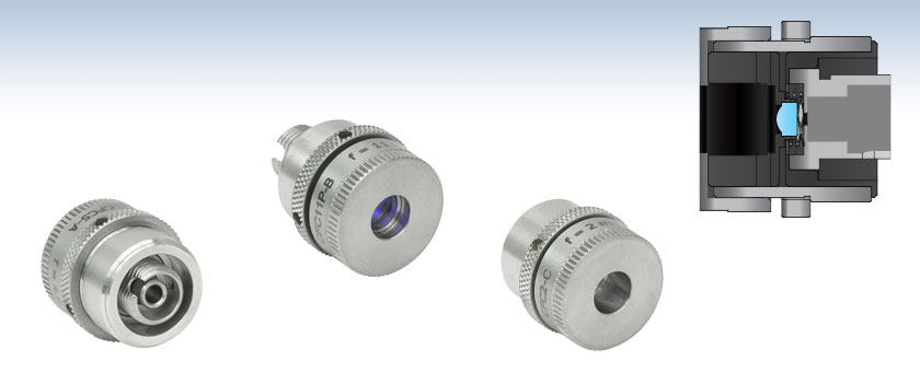
CFC5-A
f = 4.6 mm,
350 - 700 nm
(Back View)
CFC11P-B
f = 11.0 mm,
650 - 1050 nm
(Front View)
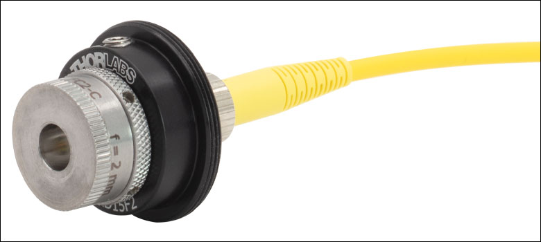
Adjustable Aspheric Collimator with an FC/PC Receptacle
CFC2-C
f = 2.0 mm,
1050 - 1700 nm
(Front View)


Please Wait
Design Improvements
We recently redesigned these adjustable fiber collimators for better performance. Improvements include:
- Tighter Dimensional Tolerances for Improved Pointing Stability
- Custom-Machined Threading for Accurate, Precise Positioning
- Locking Ring Applies Force More Evenly Than Locking Setscrew
- Captive Lens Cell
Features
- Collimate Light in Fiber-to-Free Space Applications
- Four Focal Length Options: 2.0 mm, 4.6 mm, 7.5 mm, and 11.0 mm
- Three AR-Coated Aspheric Lens Options:
- 350 - 700 nm
- 650 - 1050 nm (600 - 1050 nm for CFC2-B)
- 1050 - 1620 nm (1050 - 1700 nm for CFC2-C)
- FC/PC Receptacle with a 2.1 mm Wide Key
- Diffraction-Limited Performance when Used with Compatible Connector (See Tables G1.1, G2.1, G3.1, and G4.1)
- Pointing Error of <15 mrad During Adjustment
Thorlabs' Adjustable Focus FC/PC Collimators consist of a spring-loaded, AR-coated aspheric lens mounted inside a stainless steel cell. They are designed to collimate light exiting a fiber; for fiber-to-fiber coupling, we recommend using our FiberPorts or a fiber launch nanopositioning stage.
Rotation of the outer barrel of the collimator leads to non-rotating translation of the housed aspheric lens along the optical axis, making it possible to adjust the distance between the lens and the tip of the fiber (see the Fiber-to-Lens Distance in Tables G1.1, G2.1, G3.1, and G4.1). The dark band on the threading, shown in Figure 1.2, indicates the farthest recommended position of the outer barrel; adjusting the collimator beyond this position will lead to decreased performance outside of the guaranteed specifications. Once the desired position is reached, the adjustment can be locked into place using the knurled locking ring on the outside of the housing. See Video 1.1 for usage instructions.
These collimators feature a non-rotating lens cell, and the adjustment mechanism is designed to minimize beam pointing error. Pointing stability is within 15 mrad for 2.0 mm focal length collimators, 5 mrad for 4.6 mm and 7.5 mm focal length collimators, and 1 mrad for 11.0 mm focal length collimators. Please see Tables G1.1, G2.1, G3.1, and G4.1 for complete specifications.
We recommend using these adjustable collimators with our AR-coated single mode fiber optic patch cables. These cables feature an antireflective coating on one fiber end for increased transmission and improved return loss at the fiber-to-free-space interface. Alternatively, our large selection of standard fiber patch cables can also be used.
The collimators can be mounted by securing the Ø15 mm section of their housings in AD15F2 collimator adapters, as shown in Figure 1.3. The adapter's external SM1 (1.035"-40) threads allow it to be integrated with our wide selection of SM1-threaded optomechanics.

Click to Enlarge
Figure 1.2 The adjustable collimators have a dark band on the threading to indicate the limit of the collimator's specified adjustment range. Pointing stability and other stated specifications are not valid when the collimator is extended past this region.
Click to Enlarge
Figure 1.3 These collimators can be mounted using an AD15F2 Externally SM1-Threaded Adapter.
| Table 2.1 Stability | |||
|---|---|---|---|
| New Item # Prefixa | New Pointing Stability | Former-Generation Item # Prefixa | Former-Generation Pointing Stability |
| CFC2 | <15 mrad | CFC-2X | >50 mrad (Typ.) |
| CFC5 | <5 mrad | CFC-5X | >15 mrad (Typ.) |
| CFC8 | <5 mrad | CFC-8X | >7 mrad (Typ.) |
| CFC11P | <1 mrad | CFC-11X | >2 mrad (Typ.) |
Improved Pointing Stability
We redesigned our adjustable fiber collimators to minimize beam pointing error. By carefully controlling the dimensional tolerances, we were able to improve the pointing stability significantly, as shown in Table 2.1. Standard metal-to-metal contact points will wear down over time; we selected specific materials with high galling resistance to mitigate this effect and ensure long-term stability. Using our in-house machining capabilities, we designed a special adjuster threading for high resolution, superior centration, and minimal backlash. Lastly, we locked the lens cell to prevent any pitch or yaw movements during adjustment.
Improved Locking Hysteresis
Former-generation adjustable fiber collimators used a locking setscrew to secure the position of the outer barrel and fix the lens position. This design applied unnecessary transverse force on the lens cell, leading to misalignment and greater pointing error. The redesigned collimators use a locking ring that applies force uniformly over the rotating barrel, thus maintaining the beam pointing stability.
The graphs below show the reflectance with respect to wavelength of the AR coatings used on the aspheric lenses in our adjustable fiber collimators. Reflectance values are per surface.

Click to Enlarge
Click Here to Download Raw Data
See the tables below for more information about the AR coating wavelength range that applies to each fiber collimator.

Click to Enlarge
Click Here to Download the Raw Data
See the tables below for more information about the AR coating wavelength range that applies to each fiber collimator.
The graphs below illustrate the theoretical 1/e2 beam diameter as a function of propagation distance at the specified wavelengths using our adjustable fiber collimators adjusted for the minimum divergence. Note that the beam diameter depends on the physical properties of the aspheric lens, such as focal length and NA, and is independent of the AR coating.
Theoretical Approximation of the Divergence Angle
The full-angle beam divergence listed in the specifications tables is the theoretically-calculated value associated with the fiber collimator. This divergence angle is easy to approximate theoretically using the formula below as long as the light emerging from the fiber has a Gaussian intensity profile. Consequently, the formula works well for single mode fibers, but it will underestimate the divergence angle for multimode (MM) fibers since the light emerging from an MM fiber has a non-Gaussian intensity profile.
The Full Divergence Angle (in degrees) is given by
where MFD is the mode field diameter and f is the focal length of the collimator. (Note: MFD and f must have the same units in this equation).
Example:
In this example, the CFC2-A collimator with f = 2.0 mm is used with the P1-460B-FC-2 single mode patch cable, which has an MFD = 2.8 - 4.1 µm at 488 nm. For the purposes of this example calculation, we will use the average of the MFD range (3.5 µm), which yields a divergence angle of
θ ≈ (0.0035 mm / 2.0 mm) * (180/3.1416) ≈ 0.100° or 1.75 mrad.
Theoretical Approximation of the Output Beam Diameter
The output beam diameter can be approximated from
where λ is the wavelength of light being used, MFD is the mode field diameter, and f is the focal length of the collimator.
Example:
When the CFC5-C collimator (f = 4.6 mm) is used with the P1-SMF28E-FC-1 patch cable (average MFD = 10.4 µm) and 1550 nm light, the output beam diameter is
4 * (1550 nm) * [4.6 mm / (π · 10.4 µm)] = 0.87 mm
Theoretical Approximation of the Maximum Waist Distance
The maximum waist distance, which is the furthest distance from the lens the waist can be located in order to maintain collimation, may be approximated by:
where f is the focal length of the collimator, λ is the wavelength of light used, and MFD is the mode field diameter.
Example:
In this example, the CFC2-A collimator with f = 2.0 mm is used with the P1-460B-FC-2 single mode patch cable, which has an MFD = 2.8 - 4.1 µm at 488 nm. For the purposes of this example, we will use the average of the MFD range (3.5 µm) and calculate the maximum waist distance for a 488 nm beam:
(2 mm) + (2 * (2 mm)2 * (488 nm) / (3.1416) * (3.5 µm)2) = 103 mm.

Insights into Beam Characterization
Scroll down to read about:
- Beam Size Measurement Using a Chopper Wheel
Click here for more insights into lab practices and equipment.
Beam Size Measurement Using a Chopper Wheel
Click to Enlarge
Figure 2: The blade traces an arc length of Rθ through the center of the beam and has an angular rotation rate of  f. The chopper wheel shown is MC1F2.
Click to Enlarge
Figure 1: An approximate measurement of beam size can be found using the illustrated setup. As the blade of the chopper wheel passes through the beam, an S-curve is traced out on the oscilloscope.
Click to Enlarge
Figure 4: The diameter of a Gaussian beam is often given in terms of the 1/e2 full width.

Click to Enlarge
Figure 3: Rise time (tr ) of the intensity signal is typically measured between the 10% and 90% points on the curve. The rise time depends on the wheel's rotation rate and the beam diameter.
Camera and scanning-slit beam profilers are tools for characterizing beam size and shape, but these instruments cannot provide an accurate measurement if the beam size is too small or the wavelength is outside of the operating range.
A chopper wheel, photodetector, and oscilloscope can provide an approximate measurement of the beam size (Figure 1). As the rotating chopper wheel's blade passes through the beam, an S-shaped trace is displayed on the oscilloscope.
When the blade sweeps through the angle θ , the rise or fall time of the S-curve is proportional to the size of the beam along the direction of the blade's travel (Figure 2). A point on the blade located a distance R from the center of the wheel sweeps through an arc length (Rθ ) that is approximately equal to the size of the beam along this direction.
To make this beam size measurement, the combined response of the detector and oscilloscope should be much faster than the signal's rate of change.
Example: S-Curve with Rising Edge
The angle ftr )ftr )
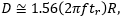
includes a factor of 1.56, which accounts for the portion of the beam measured between the 10% and 90% intensity points being smaller than the 1/e2 beam diameter.
Date of Last Edit: June 22, 2021
Content improved by our readers!
| Posted Comments: | |
user
(posted 2023-04-14 12:12:55.423) Hi, is it possible to know the exact model of the aspheric lens mounted in the collimator CFC11A-B? jgreschler
(posted 2023-04-14 08:23:49.0) Thank you for reaching out to Thorlabs. Component information is available by reaching out to techsupport@thorlabs.com. I have contacted you directly to provide the lens part number. Boerge Hemmerling
(posted 2023-04-04 18:03:49.857) Hi,
what is the power damager threshold for these collimators, e.g. CFC2-A?
We have a 30W fiber laser that I would like to connect to this type of collimator.
Thank you. cdolbashian
(posted 2023-04-13 11:10:31.0) Thank you for reaching out to us with this inquiry. Damage of optical coatings depends on the power density at the surface of the optic. We generally spec that the -A coating can handle up to 500W/cm linear power density. That being said, we would need to know the fiber you are using to properly estimate whether or not your component would be damaged. I have reached out to you directly to discuss this. Matias Berasategui
(posted 2023-04-03 07:14:57.59) Hello,
I would like to ask for a formal quote for product CFC5A-B.
Thank you,
Matias Berasategui. jgreschler
(posted 2023-04-03 08:33:07.0) Thank you for reaching out to Thorlabs. Formal quotes for stock items can be requested by emailing sales@thorlabs.com. I have arranged for one to be sent to your provided email address. charleshicks charleshicksBM
(posted 2022-09-22 00:45:51.397) cilong zhang
(posted 2022-03-13 12:50:10.93) Hi, I've got CFC2A, when distance get closer, the divergence of light get smaller, but even if set the closest distance, the light still divergent. Can you give me some advice, my laser wavelenght is 488nm(FC/APC) cdolbashian
(posted 2022-03-25 11:56:18.0) Thank you for reaching out to us with this inquiry. This type of feedback is hard to address without some more specific details regarding the fiber you are using and the effect you are observing. I have reached out to you directly to better understand the conditions under which you are implementing your component. Carl Thomas
(posted 2022-03-06 12:38:20.67) Hi-
I am hoping you can help me select the best fiber collimator for my application.
I would like to fiber couple 2 wavelengths (650 nm and 493 nm, both ~2mm spot size at input to collimator and merged on a dichroic before the collimator) into a APC s460HP fiber. Based on this, I believe the CFC11A-A collimator would be the best choice. Is this correct?
If I select this collimator, I will only be able to optimize the apsheric lens position for a single wavelength due to the focal shift. Can you recommend an appropriate second lens and position to place in one of the beam paths to compensate for the focal shift and optimize coupling for both wavelengths? Thanks cdolbashian
(posted 2022-03-15 10:54:43.0) Thank you for reaching out to us Carl. What you are looking to construct is an achromatic coupler/collimator. Using the information you provided, there would be ~200um focal shift between the two wavelengths provided, assuming all other conditions are identical. It is nontrivial to add just a single element optic in the optical path to make the focal point of both of these wavelength coincide at a single point for optimal coupling. Since you are already intending to use the adjustable focus collimator, you should be able to find a good position for coupling, then subsequently adjust the z-position of the collimator when changing wavelengths. I have reached out to you directly to discuss this further. user
(posted 2021-12-06 18:00:05.237) It would be nice to have APC fiber compatibility for focal lengths of less than f = 11 mm. The old collimators used to be APC compatible, and I'm disappointed to see this change. YLohia
(posted 2021-12-07 10:55:52.0) Hello, thank you for your feedback. We are in the process of releasing additional focal lengths (2mm, 5mm, and 8mm -- subject to change) in the line for APC connectors and hope to release it by Q1 2022. Andrew Davies
(posted 2020-08-06 01:57:49.34) Can I get a Zemax file for CFC11A-B? A black box lens would work. I want to get an idea of the chromatic aberration in my system. nbayconich
(posted 2020-08-07 05:14:46.0) Thank you for contacting Thorlabs. I will reach out to you directly to share the zemax file of the lens used in this collimation package. user
(posted 2020-04-24 17:43:34.267) Do you have any further information on the lens used -- i.e. which model does it correspond to exactly and the focal length shift with wavelength? YLohia
(posted 2020-04-27 09:36:20.0) Hello again, the CFC5 uses our A390 asphere. The focal length shift vs wavelength information can be found here : https://www.thorlabs.com/images/TabImages/A390_Asph.pdf user
(posted 2020-04-24 15:07:37.373) Hi, what material is the aspheric lens made of? YLohia
(posted 2020-04-24 04:41:37.0) Hello, thank you for contacting Thorlabs. The lens in CFC5-C is made of H-LAK54. sarmad albanna
(posted 2020-04-16 13:57:43.413) Hi there,
I am interested in this collimator but i am not clear on :
q1:if it is one device that can change the focal length using the barrel and the locking barrel from f=11 mm down to 2 mm? if so then why there are multiple devices?
q2: do you have the same device but instead of the manual adjustment of the focal length its electronic? please let me know asap Many thanks, Sarmad YLohia
(posted 2020-04-16 03:22:09.0) Hello Sarmad, thank you for contacting Thorlabs. The device does not change the focal length of the lens (this is a fixed quantity) -- instead, it allows for the adjustment of the focus, which is the distance between the lens and the fiber tip. Unfortunately, we currently do not offer a motorized focus adjuster for collimation lenses. For a motorized alternative, you may use our NanoMax (for example the MAX383) series of stages and supply your own fixed focal length aspheric lens. luis.pascual
(posted 2017-07-03 08:51:19.5) Regarding the CFC-5X-A collimator head. Could you please indicate me the allowed thermal range (for survival and for performances)?
Thank you and best regards tfrisch
(posted 2017-08-03 03:07:44.0) Hello, thank you for contacting Thorlabs. These collimators would not be damaged as high as 75°C, but there would likely be thermal expansion compared to alignment at room temperature. I see you have already been in contact with Tech Support concerning the specifics of your application. user
(posted 2017-06-19 15:38:34.617) Hi,
Looking at the calculations for the theoretical output beam diameter, I was wondering you take the FWHM, sigma or 1/e^2 as the diameter of the beam. tfrisch
(posted 2017-06-27 09:38:19.0) Hello, thank you for contacting Thorlabs. The beam diameter is given as 1/e^2. benalunda10
(posted 2017-06-15 11:49:31.453) We recently bought two products from you, LP405-SF10 and LDM9LP. You currently provide a collimation package F671FC-405 which has a beam diameter of omly 0.63 mm. We however need a collimation package that can give us a beam diameter of 1.4 mm. We have considered using an adjustable aspheric FC collimator CFC-8X-A.
By using the adjustable aspheric lens, are we able to collect all the power given the larger focal length on 7.23 mm?
What are we likely to loose by using the CFC-8X-A?
Please let us know if we can get a similar performance as when using F671FC-405. tfrisch
(posted 2017-06-27 08:32:30.0) Hello, thank you for contacting Thorlabs. It looks like you have already been in contact with our Tech Support Team about how CFC are single lens systems and as such, there is one position for which the output is collimated. This adjustment is intended to help adjust for chromatic focal shift of the lens used with different wavelengths. In order to achieve a larger diameter collimated output, a longer focal length lens should be used. nheer2
(posted 2016-04-28 11:55:45.263) by referring to the equipment here as "Adjustable" do we here mean that the diameter of the collimated beam coming out of the collimator is continuously adjustable? if yes what is the range for these diameter values and if no what do you refer to as adjustable? besembeson
(posted 2016-04-28 02:16:17.0) Response from Bweh at Thorlabs USA: By adjustable, we mean the lens housing is designed such that the lens position relative to the fiber tip can be adjusted to optimize beam collimation for different wavelengths over the AR coated spectrum. If you are looking for adjustable beam diameter collimation packages, we have these at the following page: http://www.thorlabs.com/newgrouppage9.cfm?objectgroup_ID=8642 yuns.jeon
(posted 2014-12-04 03:10:52.44) I reviewed the lens element in the CFC-5X-B. It turned out that its back focal length is 2.79 mm. But the adjustable range of the CFC-5X-B is 4.4~6.1, which is far away from the calculated number. Could you advice me in use of CFC-5X-B with corning fiber PM850 in the purpose of collimation. jlow
(posted 2014-12-12 09:22:10.0) Response from Jeremy at Thorlabs: Thank you for your feedback. The 4.4-6.1mm distance is referenced to the principal plane inside the lens. We will update the website to make the presentation clearer. shizg
(posted 2014-04-29 10:03:55.927) 请问这款可调焦准直器是否电动,另外调焦范围有多大? jlow
(posted 2014-04-29 08:17:20.0) Response from Jeremy at Thorlabs: We do not have a motorized version of the CFC series at the moment. You can find the adjustment range in the column "Fiber-to-Lens Distance", given in the table on each subgroup. bdada
(posted 2012-03-01 14:25:00.0) Response from Buki at Thorlabs:
The M18L01 patch cable uses the AFS105/125Y fiber, which has a 105um core diameter. Using ray optics for multimode fiber, you would get:
Beam Diameter (mm)= 2 x f (mm) x NA (fiber)
For example, with CFC-5X-C, the output beam diameter is approximately 0.87mm (refer to the "Calculations" tab on our website for details)
However, with the 105um core multimode fiber, the approximate beam diameter would be 2mm (2 x 4.6mm x 0.22). This is more than twice the expected beam diamter of the collimated beam when using a single mode fiber.
Please contact TechSupport@thorlabs.com if you have any questions. bdada
(posted 2012-02-13 15:12:00.0) Response from Buki at Thorlabs to aleksander.budnicki:
Thank you for your interest in the CFC-8X-B. We have contacted you to provide more information. aleksander.budnicki
(posted 2012-02-13 13:44:30.0) I've got one question regarding CFC-8x-B fiber collimator. Could you be as kind as possible an provide me the tolerance of dimensions, I have already downloaded some drawings but no information about.
Thanks in Advance,
Aleksander Budnicki Pontusw
(posted 2012-01-05 04:18:43.0) How much, aproximately, would the result in calculating divergence, beam width and Max Waist Distance change if a step index multimode fibre (M18L01) is used? user
(posted 2011-12-08 15:03:46.0) A response from Tyler at Thorlabs: Using gaussian beam propogation formulas the max waist distance is the maximum theoretical distance that the beam waist can be from the collimation lens. The wavefront of the collimated beam is flat at the beam waist. user
(posted 2011-12-07 11:02:01.0) Hi, can you please clarify the calculation behind the Max Waist Distance? Thanks. Thorlabs
(posted 2010-08-03 11:59:04.0) Response from Javier at Thorlabs to day: Thank you for your feedback. The CFC-8X-C is compatible with both FC/PC and FC/APC connectors. The reason is that the short distance between the tip of the connector and the lens makes the angular deviation negligible. day
(posted 2010-08-03 09:49:40.0) For the CFC-8X-C, do we need to specify the connector: FC/APC? |
Fiber Collimator Selection Guide
Click on the collimator type or photo to view more information about each type of collimator.
| Type | Description | |
|---|---|---|
| Fixed FC, APC, or SMA Fiber Collimators | 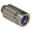 |
These fiber collimation packages are pre-aligned to collimate light from an FC/PC-, FC/APC-, or SMA-terminated fiber. Each collimation package is factory aligned to provide diffraction-limited performance for wavelengths ranging from 405 nm to 4.55 µm. Although it is possible to use the collimator at detuned wavelengths, they will only perform optimally at the design wavelength due to chromatic aberration, which causes the effective focal length of the aspheric lens to have a wavelength dependence. |
| Air-Spaced Doublet, Large Beam Collimators | 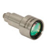 |
For large beam diameters (Ø5.3 - Ø8.5 mm), Thorlabs offers FC/APC, FC/PC, and SMA air-spaced doublet collimators. These collimation packages are pre-aligned at the factory to collimate a laser beam propagating from the tip of an FC or SMA-terminated fiber and provide diffraction-limited performance at the design wavelength. |
| Triplet Collimators | 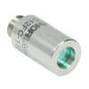 |
Thorlabs' High Quality Triplet Fiber Collimation packages use air-spaced triplet lenses that offer superior beam quality performance when compared to aspheric lens collimators. The benefits of the low-aberration triplet design include an M2 term closer to 1 (Gaussian), less divergence, and less wavefront error. |
| Achromatic Collimators for Multimode Fiber | 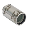 |
Thorlabs' High-NA Achromatic Collimators pair a meniscus lens with an achromatic doublet for high performance across the visible to near-infrared spectrum with low spherical aberration. Designed for use with high-NA multimode fiber, these collimators are ideal for Optogenetics and Fiber Photometry applications. |
| Reflective Collimators | 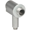 |
Thorlabs' metallic-coated Reflective Collimators are based on a 90° off-axis parabolic mirror. Mirrors, unlike lenses, have a focal length that remains constant over a broad wavelength range. Due to this intrinsic property, a parabolic mirror collimator does not need to be adjusted to accommodate various wavelengths of light, making them ideal for use with polychromatic light. Our fixed reflective collimators are recommended for collimating single and multimode fiber and coupling into multimode fiber. These collimators are available with UV-enhanced aluminum or protected silver reflective coatings and with FC/PC, FC/APC, or SMA connector compatibility. |
| Compact Reflective Collimators |  |
Thorlabs' Compact Reflective Collimators incorporate a 90° off-axis parabolic mirror with a protected silver coating. Because the focal length is independent of wavelength for an off-axis parabolic mirror, they are ideal for use with polychromatic light. Our fixed reflective collimators are recommended for collimating single and multimode fiber and coupling into multimode fiber. These collimators are directly compatible with our 16 mm cage system. They are available with FC/PC, FC/APC, or SMA connector inputs. |
| Adjustable Reflective Collimators | 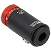 |
Thorlabs' Adjustable Focus Reflective Collimators use a 90° off-axis parabolic (OAP) mirror with a protected silver coating to collimate light from a fiber or couple light into a fiber. The adjustable fiber-to-OAP distance, combined with the OAP having a constant focal length across wavelengths, makes these collimators ideal for optimizing collimation or coupling of polychromatic light with single mode or multimode fiber. These adjustable collimators have a 15.0 mm or 33.0 mm reflected focal length and are available with FC/PC, FC/APC, or SMA connectors. |
| FiberPorts | 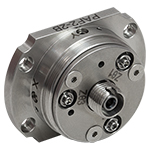 |
These compact, ultra-stable FiberPort micropositioners provide an easy-to-use, stable platform for coupling light into and out of FC/PC, FC/APC, or SMA terminated optical fibers. It can be used with single mode, multimode, or PM fibers and can be mounted onto a post, stage, platform, or laser. The built-in aspheric or achromatic lens is available with five different AR coatings and has five degrees of alignment adjustment (3 translational and 2 pitch). The compact size and long-term alignment stability make the FiberPort an ideal solution for fiber coupling, collimation, or incorporation into OEM systems. |
| Adjustable Fiber Collimators |  |
These collimators are designed to connect onto the end of an FC/PC, FC/APC, or SMA connector and contain an AR-coated aspheric lens. The distance between the aspheric lens and the tip of the fiber can be adjusted to compensate for focal length changes or to recollimate the beam at the wavelength and distance of interest. |
| Achromatic Fiber Collimators with Adjustable Focus |  |
Thorlabs' Achromatic Fiber Collimators with Adjustable Focus are designed with an effective focal length (EFL) of 20 mm, 40 mm, or 80 mm, have optical elements broadband AR coated for one of three wavelength ranges, and are available with FC/PC, FC/APC, or SMA905 connectors. A four-element, air-spaced lens design produces superior beam quality (M2 close to 1) and less wavefront error when compared to aspheric lens collimators. These collimators can be used for free-space coupling into a fiber, collimation of output from a fiber, or in pairs for collimator-to-collimator coupling over long distances, which allows the beam to be manipulated prior to entering the second collimator. |
| Zoom Fiber Collimators | 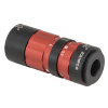 |
These collimators provide a variable focal length between 6 and 18 mm, while maintaining the collimation of the beam. As a result, the size of the beam can be changed without altering the collimation. This universal device saves time previously spent searching for the best suited fixed fiber collimator and has a very broad range of applications. They are offered with FC/PC, FC/APC, or SMA905 connectors with three different antireflection wavelength ranges to choose from. |
| Single Mode Pigtailed Collimators | 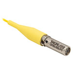 |
Our single mode pigtailed collimators come with one meter of fiber, consist of an AR-coated aspheric lens pre-aligned with respect to a fiber, and are collimated at one of eight wavelengths: 532 nm, 633 nm, 780 nm, 850 nm, 1030 nm, 1064 nm, 1310 nm, or 1550 nm. Although it is possible to use the collimator at any wavelength within the coating range, the coupling loss will increase as the wavelength is detuned from the design wavelength. |
| Polarization Maintaining Pigtailed Collimators | 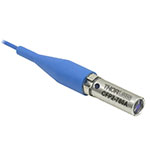 |
Our polarization maintaining pigtailed collimators come with one meter of fiber, consist of an AR-coated aspheric lens pre-aligned with respect to a fiber, and are collimated at one of five wavelengths: 633 nm, 780 nm, 980 nm, 1064 nm, or 1550 nm. Custom wavelengths and connectors are available as well. A line is engraved along the outside of the housing that is parallel to the fast axis. As such, it can be used as a reference when polarized light is launched accordingly. Although it is possible to use the collimator at any wavelength within the coating range, the coupling loss will increase as the wavelength is detuned from the design wavelength. |
| GRIN Fiber Collimators |  |
Thorlabs offers gradient index (GRIN) fiber collimators that are aligned at a variety of wavelengths from 630 to 1550 nm and have either FC terminated, APC terminated, or unterminated fibers. Our GRIN collimators feature a Ø1.8 mm clear aperture, are AR-coated to ensure low back reflection into the fiber, and are coupled to standard single mode or graded-index multimode fibers. |
| GRIN Lenses |  |
These graded-index (GRIN) lenses are AR coated for applications at 630, 830, 1060, 1300, or 1560 nm that require light to propagate through one fiber, then through a free-space optical system, and finally back into another fiber. They are also useful for coupling light from laser diodes into fibers, coupling the output of a fiber into a detector, or collimating laser light. Our GRIN lenses are designed to be used with our Pigtailed Glass Ferrules and GRIN/Ferrule sleeves. |
| Table G1.1 Specifications | ||||||||||
|---|---|---|---|---|---|---|---|---|---|---|
| Item # | f (mm) |
NAa | Input MFDb |
Output Waist Diameter (1/e2) |
Max Waist Distancec |
Pointing Stability During Collimation |
Divergenced | Fiber-to-Lens Distancee |
AR Coatingf | Compatible Connector |
| CFC2-A | 2.0 | 0.5 | 3.5 µm | 0.36 mmg | 103.4 mmg | <15 mrad | 0.100°g | 0.4 - 3.0 mm | 350 - 700 nm | 2.1 mm Wide Key FC/PC |
| CFC2-B | 2.0 | 0.5 | 5.0 µm | 0.43 mmh | 88.6 mmh | <15 mrad | 0.143°h | 0.4 - 3.0 mm | 600 - 1050 nm | |
| CFC2-C | 2.0 | 0.5 | 10.4 µm | 0.38 mmi | 38.5 mmi | <15 mrad | 0.298°i | 0.4 - 3.0 mm | 1050 - 1700 nm | |
| Table G2.1 Specifications | ||||||||||
|---|---|---|---|---|---|---|---|---|---|---|
| Item # | f (mm) |
NAa | Input MFDb |
Output Waist Diameter (1/e2) |
Max Waist Distancec |
Pointing Stability During Collimation |
Divergenced | Fiber-to-Lens Distancee |
AR Coatingf | Compatible Connector |
| CFC5-A | 4.6 | 0.53 | 3.5 µm | 0.82 mmg | 541.2 mmg | <5 mrad | 0.044°g | 2.4 - 4.9 mm | 350 - 700 nm | 2.1 mm Wide Key FC/PC |
| CFC5-B | 4.6 | 0.53 | 5.0 µm | 1.00 mmh | 462.6 mmh | <5 mrad | 0.062°h | 2.4 - 4.9 mm | 650 - 1050 nm | |
| CFC5-C | 4.6 | 0.53 | 10.4 µm | 0.87 mmi | 197.7 mmi | <5 mrad | 0.130°i | 2.4 - 4.9 mm | 1050 - 1620 nm | |
| Table G3.1 Specifications | ||||||||||
|---|---|---|---|---|---|---|---|---|---|---|
| Item # | f (mm) |
NAa | Input MFDb |
Output Waist Diameter (1/e2) |
Max Waist Distancec |
Pointing Stability During Collimation |
Divergenced | Fiber-to-Lens Distancee |
AR Coatingf | Compatible Connector |
| CFC8-A | 7.5 | 0.3 | 3.5 µm | 1.33 mmg | 1434.1 mmg | <5 mrad | 0.027°g | 4.2 - 6.8 mm | 350 - 700 nm | 2.1 mm Wide Key FC/PC |
| CFC8-B | 7.5 | 0.3 | 5.0 µm | 1.62 mmh | 1225.0 mmh | <5 mrad | 0.038°h | 4.2 - 6.8 mm | 650 - 1050 nm | |
| CFC8-C | 7.5 | 0.3 | 10.4 µm | 1.42 mmi | 520.7 mmi | <5 mrad | 0.079°i | 4.2 - 6.8 mm | 1050 - 1620 nm | |
| Table G4.1 Specifications | ||||||||||
|---|---|---|---|---|---|---|---|---|---|---|
| Item # | f (mm) |
NAa | Input MFDb |
Output Waist Diameter (1/e2) |
Max Waist Distancec |
Pointing Stability During Collimation |
Divergenced | Fiber-to-Lens Distancee |
AR Coatingf | Compatible Connector |
| CFC11P-A | 11.0 | 0.3 | 3.5 µm | 1.95 mmg | 3079.7 mmg | <1 mrad | 0.018°g | 8.6 - 10.9 mm | 350 - 700 nm | 2.1 mm Wide Key FC/PC |
| CFC11P-B | 11.0 | 0.3 | 5.0 µm | 2.38 mmh | 2630.1 mmh | <1 mrad | 0.026°h | 8.6 - 10.9 mm | 650 - 1050 nm | |
| CFC11P-C | 11.0 | 0.3 | 10.4 µm | 2.09 mmi | 1114.9 mmi | <1 mrad | 0.054°i | 8.6 - 10.9 mm | 1050 - 1620 nm | |