 Products Home / Fiber Components / Collimation / Coupling / High-NA Achromatic Collimators for Multimode Fibers
High-NA Achromatic Collimators for Multimode Fibers

- Achromatic Performance Across Visible Spectrum
- AR Coatings Cover 350 to 1700 nm
- Options for FC/PC or SMA Connectors
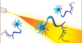
- Ideal for Fiber Photometry Applications
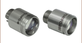
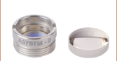
F950SMA-A
SMA905 Multimode Collimator
Front
Front
Back
Back
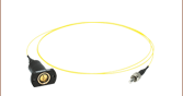
F950FC-C
FC/PC Multimode Collimator
Our multimode collimators contain a cemented achromatic doublet and a meniscus lens.


Please Wait
 Zemax Files Zemax Files |
|---|
| Click on the red Document icon next to the item numbers below to access the Zemax file download. Our entire Zemax Catalog is also available. |
Features
- High-NA Achromatic Collimators for Multimode Fiber
- Factory Aligned at 473, 850, or 1310 nm
- 10 mm Effective Focal Length
- Ø11.0 mm Clear Aperture
- Can Be Used as a Coupler or Collimator
- Available with Either FC/PC 2.2 mm Wide Key or SMA905 Connectors
- Non-Magnetic Stainless Steel Housing
Thorlabs' High-NA Achromatic Collimators are designed for use with high-NA multimode fiber, and are therefore ideal for applications such as fiber photometry. These triplet collimators feature a meniscus lens and an achromatic doublet for high performance across the visible spectrum with low spherical abberation. The optics are offered with our -A, -B, or -C broadband antireflection (AR) coatings for 350 to 700 nm, 650 to 1050 nm, or 1050 to 1700 nm, respectively, at the air-to-glass interfaces to minimize losses caused by surface reflections. The collimators with Item # suffixes -A, -B, and -C are factory aligned at 473, 850, and 1310 nm, respectively. The collimator housing includes either an FC/PC 2.2 mm wide key connector or an SMA905 port; typically, FC/PC collimators will offer better coupling efficiency.
The multimode collimators are compatible with the AD15F, AD15NT, and AD15F2 adapters for setups requiring SM1-threaded or Ø1" smooth bore compatibility; additional collimator mounting adapters are also available. When using these collimators as a free-space coupler, precise alignment is needed for good coupling efficiency. For autofluorescence and fiber photometry applications, our fluorescence filter cube is ideal for directing a free-space collimated beam towards fluorescence imaging filters. It is also possible to use a kinematic tip-and-tilt mount paired with an XYZ adjustable platform (such as our KM100V Kinematic V-Mount and MT3(/M) XYZ Translation Stage). Please note that using these collimators without a kinematic mount will introduce 1 dB of loss or more.
Thorlabs offers a wide variety of multimode patch cables that can be used with these collimators, including lightweight cables for optogenetics and low-autofluorescence cables for fiber photometry applications.
We also offer a line of aspheric fiber collimators, including our fixed collimators and our FiberPort adjustable collimation packages, that are well suited for use with a wide range of wavelengths. For our complete line of collimation and coupling options, please see the Collimator Guide tab.
| Item # | Alignment Wavelength |
Lens AR Coatinga | Beam Diameterb,c | Full-Angle Divergenceb |
Focal Lengthd |
Connector Style | NA | Le |
|---|---|---|---|---|---|---|---|---|
| F950FC-Af | 473 nm | 350 - 700 nm Ravg < 0.5% |
LED Source: 10.0 mm Laser Source: 4.5 mm |
1.0° | 9.9 mm | 2.2 mm Wide Key FC/PC | 0.54 | 28.6 mm (1.13") |
| F950SMA-Af | SMA905 | 31.5 mm (1.24") | ||||||
| F950FC-B | 850 nm | 650 - 1050 nm Ravg < 0.5% |
LED Source: 10.0 mm Laser Source: 2.5 mm |
10.1 mm | 2.2 mm Wide Key FC/PC | 28.6 mm (1.13") | ||
| F950SMA-B | SMA905 | 31.5 mm (1.24") | ||||||
| F950FC-C | 1310 nm | 1050 - 1700 nm Ravg < 0.5% |
10.2 mm | 2.2 mm Wide Key FC/PC | 28.6 mm (1.13") | |||
| F950SMA-C | SMA905 | 31.5 mm (1.24") |
Beam Diameter and Divergence
The 1/e2 beam diameter and divergence were simulated for each of our F950 collimators utilizing a laser or LED source at various wavelengths.
Click to Enlarge
Click for Raw Data
Typical 1/e2 beam diameter from a high-NA, -A coated, achromatic collimator with a single mode fiber-coupled laser input through 1 m of 0.22 NA single mode fiber (multimode fiber used for 473 nm); performance will be similar for fibers with NAs from 0.22 to 0.5.
Click to Enlarge
Click for Raw Data
Typical 1/e2 beam diameter from a high-NA, -A coated, achromatic collimator with multimode fiber-coupled LED input through 1 m of 0.50 NA fiber.
Click to Enlarge
Click for Raw Data
Typical divergence in a high-NA, -A coated, achromatic collimator with multimode light sources input through 1 m of fiber; when using a laser as the input source, performance will be similar for fiber NAs from 0.22 to 0.5.

Click to Enlarge
Click for Raw Data
Typical 1/e2 beam diameter from a high-NA, -B coated, achromatic collimator with a single mode fiber-coupled laser input through 1 m of 0.22 NA single mode fiber; performance will be similar for fibers with NAs from 0.22 to 0.5.
Click to Enlarge
Click for Raw Data
Typical 1/e2 beam diameter from a high-NA, -B coated, achromatic collimator with multimode fiber-coupled LED input through 1 m of 0.50 NA fiber.
Click to Enlarge
Click for Raw Data
Typical divergence in a high-NA, -B coated, achromatic collimator with multimode light sources input through 1 m of fiber; when using a laser as the input source, performance will be similar for fiber NAs from 0.22 to 0.5.

Click to Enlarge
Click for Raw Data
Typical 1/e2 beam diameter from a high-NA, -C coated, achromatic collimator with a single mode fiber-coupled laser input through 1 m of 0.22 NA single mode fiber; performance will be similar for fibers with NAs from 0.22 to 0.5.

Click to Enlarge
Click for Raw Data
Typical 1/e2 beam diameter from a high-NA, -C coated, achromatic collimator with multimode fiber-coupled LED input through 1 m of 0.50 NA fiber.
Click to Enlarge
Click for Raw Data
Typical divergence in a high-NA, -C coated, achromatic collimator with multimode light sources input through 1 m of fiber; when using a laser as the input source, performance will be similar for fiber NAs from 0.22 to 0.5.
Insertion Loss and AR Coating Performance
Click to Enlarge
F950 series collimators pair insertion loss measured using a previous generation SLS201 light source, an optical spectrum analyzer, and 0.39 NA, Ø200 µm core multimode optical fiber. The blue, red, and green shaded regions denote the antireflective ranges of the -A, -B, and -C coatings, respectively.
Click to Enlarge
Reflectance per surface of the broadband antireflection coating on the air-to-glass interfaces of each -A coated collimator. The blue-shaded region denotes the reflection band for which the performance is guaranteed to meet the stated specifications. Performance outside the shaded region will vary from lot to lot and is not guaranteed.
Click to Enlarge
Reflectance per surface of the broadband antireflection coating on the air-to-glass interfaces of each -B coated collimator. The blue-shaded region denotes the reflection band for which the performance is guaranteed to meet the stated specifications. Performance outside the shaded region will vary from lot to lot and is not guaranteed.
Click to Enlarge
Reflectance per surface of the broadband antireflection coating on the air-to-glass interfaces of each -C coated collimator. The blue-shaded region denotes the reflection band for which the performance is guaranteed to meet the stated specifications. Performance outside the shaded region will vary from lot to lot and is not guaranteed.

Insights into Best Lab Practices
Scroll down to read about a practice we follow when setting up lab equipment.
- Align Fiber Collimators to Create Free Space Between Fibers
Click here for more insights into lab practices and equipment.
Align Fiber Collimators to Create Free Space Between Fibers
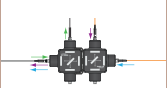
Two collimators, inserted into a fiber optic setup, provide free-space access to the beam. The first collimator accepts the highly diverging light from the first fiber and outputs a free-space beam, which propagates with an approximately constant diameter to the second collimator. The second collimator accepts the free-space beam and couples that light into the second fiber. Some collimation packages, including the pair used in this demonstration, are designed for use with optical fibers and mate directly to fiber connectors.
Ideally, 100% of the light emitted by the first fiber would be coupled into the second fiber, but some light will always be lost due to reflections, scattering, absorption, and misalignment. Misalignment, typically the largest source of loss, can be minimized using the alignment and stabilization techniques described in this video.
In this demonstration, the first fiber is single mode. The optical power incident on the second collimator, as well as the power output by the second fiber, are measured. When the second fiber is multimode with a 50 µm diameter core, alignment resulted in 91% of the power incident on the second collimator being measured at the fiber output. This value was 86% when the second fiber is single mode. Some differences in collimator designs, and their effects on the characteristics of the collimated beams, are also discussed.
If you would like more information about tips, tricks, and other methods we often use in the lab, we recommend our other Video Insights. In addition, our webinars provide practical and theoretical introductions to our different products.
| Products Featured During Demonstration | ||||
|---|---|---|---|---|
| Fiber-Coupled Laser | Kinematic Mounts | Fiber Adapter Cap (for Power Sensor) |
Single Mode Patch Cable (FC/PC) | Fiber Cable Storage Reels |
| Triplet Fiber Optic Collimators | Power Sensor | Power Meter | Hybrid Single Mode Patch Cable | 2" Posts |
| Adapter (Mount-to-Collimator) |
SM1 Thread Adapter (for Power Sensor) |
Fiber Connector Cleaner | Step-Index Multimode Patch Cable | Ø1/2" Post Holders |
Date of Last Edit: April 21, 2021
Fiber Collimator Selection Guide
Click on the collimator type or photo to view more information about each type of collimator.
| Type | Description | |
|---|---|---|
| Fixed FC, APC, or SMA Fiber Collimators | 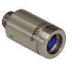 |
These fiber collimation packages are pre-aligned to collimate light from an FC/PC-, FC/APC-, or SMA-terminated fiber. Each collimation package is factory aligned to provide diffraction-limited performance for wavelengths ranging from 405 nm to 4.55 µm. Although it is possible to use the collimator at detuned wavelengths, they will only perform optimally at the design wavelength due to chromatic aberration, which causes the effective focal length of the aspheric lens to have a wavelength dependence. |
| Air-Spaced Doublet, Large Beam Collimators | 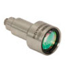 |
For large beam diameters (Ø5.3 - Ø8.5 mm), Thorlabs offers FC/APC, FC/PC, and SMA air-spaced doublet collimators. These collimation packages are pre-aligned at the factory to collimate a laser beam propagating from the tip of an FC or SMA-terminated fiber and provide diffraction-limited performance at the design wavelength. |
| Triplet Collimators |  |
Thorlabs' High Quality Triplet Fiber Collimation packages use air-spaced triplet lenses that offer superior beam quality performance when compared to aspheric lens collimators. The benefits of the low-aberration triplet design include an M2 term closer to 1 (Gaussian), less divergence, and less wavefront error. |
| Achromatic Collimators for Multimode Fiber | 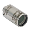 |
Thorlabs' High-NA Achromatic Collimators pair a meniscus lens with an achromatic doublet for high performance across the visible to near-infrared spectrum with low spherical aberration. Designed for use with high-NA multimode fiber, these collimators are ideal for Optogenetics and Fiber Photometry applications. |
| Reflective Collimators | 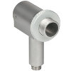 |
Thorlabs' metallic-coated Reflective Collimators are based on a 90° off-axis parabolic mirror. Mirrors, unlike lenses, have a focal length that remains constant over a broad wavelength range. Due to this intrinsic property, a parabolic mirror collimator does not need to be adjusted to accommodate various wavelengths of light, making them ideal for use with polychromatic light. Our fixed reflective collimators are recommended for collimating single and multimode fiber and coupling into multimode fiber. These collimators are available with UV-enhanced aluminum or protected silver reflective coatings and with FC/PC, FC/APC, or SMA connector compatibility. |
| Compact Reflective Collimators |  |
Thorlabs' Compact Reflective Collimators incorporate a 90° off-axis parabolic mirror with a protected silver coating. Because the focal length is independent of wavelength for an off-axis parabolic mirror, they are ideal for use with polychromatic light. Our fixed reflective collimators are recommended for collimating single and multimode fiber and coupling into multimode fiber. These collimators are directly compatible with our 16 mm cage system. They are available with FC/PC, FC/APC, or SMA connector inputs. |
| Adjustable Reflective Collimators |  |
Thorlabs' Adjustable Focus Reflective Collimators use a 90° off-axis parabolic (OAP) mirror with a protected silver coating to collimate light from a fiber or couple light into a fiber. The adjustable fiber-to-OAP distance, combined with the OAP having a constant focal length across wavelengths, makes these collimators ideal for optimizing collimation or coupling of polychromatic light with single mode or multimode fiber. These adjustable collimators have a 15.0 mm or 33.0 mm reflected focal length and are available with FC/PC, FC/APC, or SMA connectors. |
| FiberPorts | 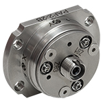 |
These compact, ultra-stable FiberPort micropositioners provide an easy-to-use, stable platform for coupling light into and out of FC/PC, FC/APC, or SMA terminated optical fibers. It can be used with single mode, multimode, or PM fibers and can be mounted onto a post, stage, platform, or laser. The built-in aspheric or achromatic lens is available with five different AR coatings and has five degrees of alignment adjustment (3 translational and 2 pitch). The compact size and long-term alignment stability make the FiberPort an ideal solution for fiber coupling, collimation, or incorporation into OEM systems. |
| Adjustable Fiber Collimators |  |
These collimators are designed to connect onto the end of an FC/PC, FC/APC, or SMA connector and contain an AR-coated aspheric lens. The distance between the aspheric lens and the tip of the fiber can be adjusted to compensate for focal length changes or to recollimate the beam at the wavelength and distance of interest. |
| Achromatic Fiber Collimators with Adjustable Focus | 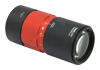 |
Thorlabs' Achromatic Fiber Collimators with Adjustable Focus are designed with an effective focal length (EFL) of 20 mm, 40 mm, or 80 mm, have optical elements broadband AR coated for one of three wavelength ranges, and are available with FC/PC, FC/APC, or SMA905 connectors. A four-element, air-spaced lens design produces superior beam quality (M2 close to 1) and less wavefront error when compared to aspheric lens collimators. These collimators can be used for free-space coupling into a fiber, collimation of output from a fiber, or in pairs for collimator-to-collimator coupling over long distances, which allows the beam to be manipulated prior to entering the second collimator. |
| Zoom Fiber Collimators | 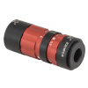 |
These collimators provide a variable focal length between 6 and 18 mm, while maintaining the collimation of the beam. As a result, the size of the beam can be changed without altering the collimation. This universal device saves time previously spent searching for the best suited fixed fiber collimator and has a very broad range of applications. They are offered with FC/PC, FC/APC, or SMA905 connectors with three different antireflection wavelength ranges to choose from. |
| Single Mode Pigtailed Collimators | 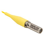 |
Our single mode pigtailed collimators come with one meter of fiber, consist of an AR-coated aspheric lens pre-aligned with respect to a fiber, and are collimated at one of eight wavelengths: 532 nm, 633 nm, 780 nm, 850 nm, 1030 nm, 1064 nm, 1310 nm, or 1550 nm. Although it is possible to use the collimator at any wavelength within the coating range, the coupling loss will increase as the wavelength is detuned from the design wavelength. |
| Polarization Maintaining Pigtailed Collimators | 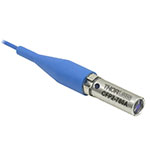 |
Our polarization maintaining pigtailed collimators come with one meter of fiber, consist of an AR-coated aspheric lens pre-aligned with respect to a fiber, and are collimated at one of five wavelengths: 633 nm, 780 nm, 980 nm, 1064 nm, or 1550 nm. Custom wavelengths and connectors are available as well. A line is engraved along the outside of the housing that is parallel to the fast axis. As such, it can be used as a reference when polarized light is launched accordingly. Although it is possible to use the collimator at any wavelength within the coating range, the coupling loss will increase as the wavelength is detuned from the design wavelength. |
| GRIN Fiber Collimators | 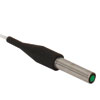 |
Thorlabs offers gradient index (GRIN) fiber collimators that are aligned at a variety of wavelengths from 630 to 1550 nm and have either FC terminated, APC terminated, or unterminated fibers. Our GRIN collimators feature a Ø1.8 mm clear aperture, are AR-coated to ensure low back reflection into the fiber, and are coupled to standard single mode or graded-index multimode fibers. |
| GRIN Lenses |  |
These graded-index (GRIN) lenses are AR coated for applications at 630, 830, 1060, 1300, or 1560 nm that require light to propagate through one fiber, then through a free-space optical system, and finally back into another fiber. They are also useful for coupling light from laser diodes into fibers, coupling the output of a fiber into a detector, or collimating laser light. Our GRIN lenses are designed to be used with our Pigtailed Glass Ferrules and GRIN/Ferrule sleeves. |
| Posted Comments: | |
Colin Stephen
(posted 2025-01-23 13:15:15.847) Hi,
Would it be possible to make these for the AB coating range? We're looking into using your 0.50 and 0.39 NA large diameter fibres with diamond NV- so need to pass 530-850 nm efficiently for excitation and broad band fluorescence collection, ideally without too much chromatic shift. What sort of lead time would there be and cost increase over your standard offerings?
Thanks,
Colin tdevkota
(posted 2025-01-24 12:09:15.0) Thank you for contacting Thorlabs. Requests for customization of our stock optics can be made by emailing us at techsupport@thorlabs.com. I have reached out to you directly to discuss the feasibility of this request. user
(posted 2024-09-26 10:51:08.517) Can i know the damage threshold of the surface coating for f950fc-a?
Because we use to focus a laser to optic fiber but it burned
Our laser is FIU-15 EGies
(posted 2024-10-02 04:15:56.0) Thank you for contacting Thorlabs. We have not performed LIDT testing of the F950FC-A collimator with a supercontinuum source. The damage threshold for this collimator will be affected by both the AR coating and by the lens and cement materials used. I have reached out to you directly regarding your specific application. Yuhao Xu
(posted 2024-07-04 12:42:13.837) Hello,
I would like to inquire about a fiber coupler for the Ocean HDX spectrometer used for visible light. Our current optical fiber is not equipped with a coupler and has a diameter of 1mm. I am looking to configure a coupler and fiber to achieve the larger possible collection area. Do you think this product is suitable? Or do you have any other recommended products?
Thank you for your assistance.
Best regards, cdolbashian
(posted 2024-07-12 08:58:05.0) Thank you for reaching out to us with this inquiry. I have contacted you directly to discuss your coupling geometry with the goal of improving your collection efficiency. Jaeheon Seol
(posted 2024-04-25 17:16:59.02) Hello Thorlabs
I would like to use this product to collimate the beam of a 450nm fiber coupled laser diode with a 0.22NA value.
The connector type is SMA905.
My question is, is there a way to adjust the distance between the lens and the fiber when the SMA 905 connector is fully engaged?
Thank you cdolbashian
(posted 2024-04-26 02:07:21.0) Thank you for reaching out to us with this inquiry. These collimators are Fixed focus collimators, and are aligned to the design wavelength in house. I would recommend using one of our adjustable aspheric collimators: https://www.thorlabs.com/newgrouppage9.cfm?objectgroup_id=15651 Wilson Adams
(posted 2023-10-20 16:18:05.263) Do y'all offer an NIR optimized / AR coated version of this component? Or is there any estimates on how this item would perform in the NIR regime? cdolbashian
(posted 2023-10-27 11:51:40.0) Thank you for reaching out to us with this inquiry Wilson! We do not have this specific collimator with the AR range you are looking for, but perhaps we have a different one which can satisfy your collimator requirements! I have contacted you directly to discuss this. 高 健
(posted 2023-09-23 09:21:27.167) 您好,这个器件可以对光纤中637nm荧光信号进行准直吗 cdolbashian
(posted 2023-10-19 02:26:34.0) Thank you for reaching out to us with this inquiry! I have contacted you directly to understand more about your application. gao jian
(posted 2023-09-22 16:36:25.37) 您好这个激光准直器可以用于637nm的荧光准直吗 cdolbashian
(posted 2023-10-02 03:55:32.0) Thank you for reaching out to us with this inquiry. Without knowing more about your microscopy design, we cannot comment on this. I would recommend reaching out to your local tech support team, techsupport-cn@thorlabs.com, for application advice. user
(posted 2023-09-12 13:53:57.44) Could Thorlabs manufacture a FC/APC version of this collimator? ksosnowski
(posted 2023-09-13 11:34:22.0) Hello, thanks for reaching out to Thorlabs. We are typically able to offer our other fiber connector options on the fixed focus collimators by special request. For inquiries like this we recommend contacting techsupport@thorlabs.com to further discuss the application and requirements. 健 高
(posted 2023-09-04 09:15:32.413) 您好,这个器件可以用于波长为637nm的荧光准直吗 cdolbashian
(posted 2023-10-19 09:03:08.0) Thank you for reaching out to us with this inquiry. Depending on your optical configuration, you certainly could use this component to gather light for fluorescence measurements. I have reached out to you to discuss your application. user
(posted 2023-05-02 16:53:09.22) The F950xx-x collimator specifies the output beam diameter as "LED Source: 10.0 mm
and Laser Source: 4.5 mm" for a "0.39 NA, Ø200 µm core multimode fiber". Why is there a difference in output beam diameters for LED versus laser sources given that the fiber itself determines the beam propagation characteristics and overwrites the beam propagation characteristics of the source? ksosnowski
(posted 2023-05-25 10:33:58.0) Thanks for reaching out to Thorlabs. The launch conditions of the source can effect the beam profile and diameter. Over a short section of multimode fiber, it is possible to launch a singlemode source and underfill some modes in the MM fiber. However LEDs and other non-point source tend to overfill an MM fiber in which case the output is highly defined by the fiber properties. I have reached out to discuss this in more detail. Eliezer Twaik
(posted 2021-11-10 11:07:30.947) Hi,
I understood that manufacturers have various definitions for NA of fibers, based on 50 percent intensity level, 5 percent intensity level, 1 percent intensity level, etc.
What is the definition that you use?
Thanks,
Eliezer jgreschler
(posted 2021-11-10 02:51:05.0) Hi Eliezer,
We define the numerical aperture of our fibers to be the square root of the difference in indices between core and cladding squared. You can read more about our convention on this page: https://www.thorlabs.com/newgrouppage9.cfm?objectgroup_id=10417 Eliezer Twaik
(posted 2021-11-10 10:52:59.92) Hi,
I'd be happy to understand, what's the exact difference between "Alignment Wavelength" and "Design Wavelengths".
Thanks,
Eliezer YLohia
(posted 2021-11-23 02:04:29.0) Hello Eliezer, thank you for contacting Thorlabs. The wavelength an optic is specifically designed for is referred to as "Design Wavelength". This is the wavelength where the optic is optimized for performance and the wavelength at which the focal length spec is valid. For other wavelengths, the focal length will shift. Since these parts are sold as systems, for proper coupling or collimation, the distance between the fiber tip and the optic needs to be set in accordance with the effective focal length (which is impacted by the focal length shift). Therefore, there is an "alignment wavelength" or the wavelength at which the entire system is optimized for. user
(posted 2021-10-12 12:24:10.687) Is there a High-NA Achromatic Collimator for Multimode Fibers in the NIR (700-1000nm) available? YLohia
(posted 2021-10-13 09:37:09.0) Hello, thank you for contacting Thorlabs. Unfortunately, we currently do not offer a high NA achromatic collimator in this packaging for that wavelength range. The closest option we current offer is the PAF2-A7B (or similar) for the 650 - 1050 nm range. Michael Brookman
(posted 2021-09-15 16:18:37.62) I am curious about the temperature rating for this part and do not see it on the page. Could you share it with me and add it? YLohia
(posted 2021-09-17 03:49:41.0) Thank you for contacting Thorlabs. The operating temperature of this part would be limited by the epoxy used in the assembly, which is specified for a temperature range of -54 to +107 C. That being said, please note that this is not a formal spec since we have only tested the collimator down to 0 C. We have also performed a limited amount of autoclave testing up to 132 C and have not seen any issues (but we cannot guarantee performance up to this temperature due to the max temp spec for the epoxy). Danny Bachman
(posted 2021-02-05 17:35:17.21) I'm trying to find the most efficient way to couple to my multimode fiber from the output of a microscope objective. The microscope objective has an output aperture of 8.4mm and the fiber has a NA of 0.22. I read that most efficient coupling is achieved by matching the NA of the collimator to the fiber so will this product work best? I was also looking at the fiberport series but the input aperture of those devices is much smaller and would probably not be efficient? YLohia
(posted 2021-02-18 10:32:17.0) Thank you for contacting Thorlabs. For the 8.4mm beam coming from the back end the objective, our F950 collimators would cause the NA of the light to be very high with respect to the fiber NA which will cause a large amount light to fall out of the angle of acceptance of the fiber. A higher efficiency option would be the C80FC-A (or C80SMA-A depending on your connector). Andreas Seifahrt
(posted 2019-10-15 05:42:06.743) Thanks for adding this product. It would be great if you would consider offering them with a broader AR coating (400-1100nm) or even uncoated for broadband applications. YLohia
(posted 2019-10-16 09:39:35.0) Hello Andreas, thank you for your feedback. I have posted your request in our internal engineering forum for further consideration by our design engineers as a future product idea. user
(posted 2019-05-27 15:01:04.69) Is NA 0.54 as stated or 0.45? YLohia
(posted 2019-05-29 08:59:13.0) Hello, yes, the NA is 0.54. If you have further questions, please feel free to contact us at techsupport@thorlabs.com. |