 Products Home / Fiber Components / Collimation / Coupling / Large-Beam Achromatic Fiber Collimators, Adjustable Focus
Large-Beam Achromatic Fiber Collimators, Adjustable Focus
- Long Effective Focal Length: 20 mm, 40 mm, or 80 mm
- FC/PC, FC/APC, or SMA Connector
- Four-Element, Air-Spaced-Lens Design
- Three AR Coating Wavelength Ranges Available
Application Idea
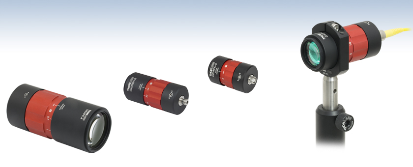
C40FC-C Collimator Mounted on a Ø1/2" Post Using an SM1RC Slip Ring
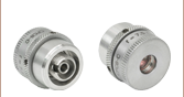
C80APC-A (Front View)
80 mm Focal Length
FC/APC Connector
AR Coated for 400 - 650 nm
C40SMA-B (Back View)
40 mm Focal Length
SMA905 Connector
AR Coated for 650 - 1050 nm
C20APC-C (Back View)
20 mm Focal Length
FC/APC Connector
AR Coated for 1050 - 1650 nm


Please Wait

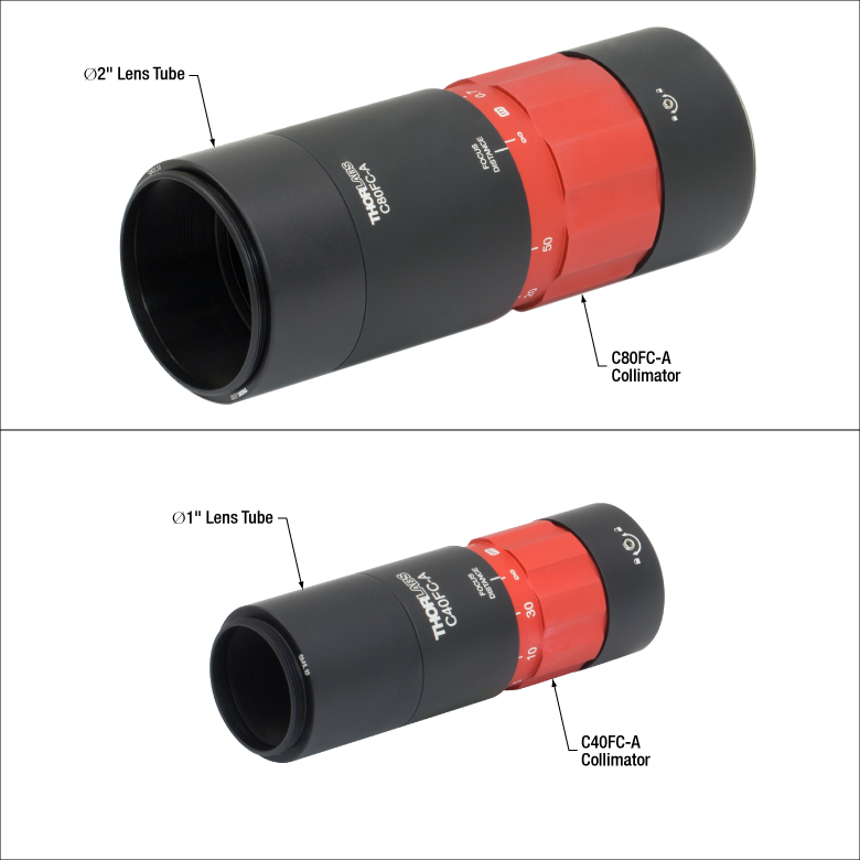
Click to Enlarge
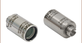
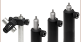
The C80 collimators have external SM2 threading on the free-space end for attaching Ø2" lens tubes, while the C40 collimators have SM1 threading for attaching Ø1" lens tubes.
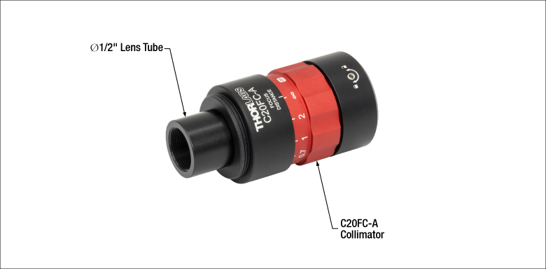
Click to Enlarge
In addition to external SM1 threading, the C20 collimators have internal SM05 threading on the free-space end for attaching Ø1/2" lens tubes.
Features
- Ideal for Fiber-to-Free-Space Collimation or Coupling
- Effective Focal Length (EFL): 20 mm, 40 mm, or 80 mm
- Accepts Input Fiber NA up to 0.25
- Large Clear Aperture: Ø10.9 mm, Ø20.5 mm, or Ø42.5 mm
- Three Broadband Antireflection Coatings Available (See the Coatings Tab for Plots)
- 400 nm - 650 nm: Rmax < 0.5%
- 650 nm - 1050 nm: Rmax < 0.5%
- 1050 nm - 1650 nm: Rmax < 0.5%
- Closest Focusing Distance: 0.2 m (20 mm EFL), 0.35 m (40 mm EFL), or 0.7 m (80 mm EFL)
- Near-Gaussian Output from Single Mode Fiber
- Excellent Off-Axis Performance for Large Multimode Fibers (See the Multimode Tab)
- Diffraction-Limited Wavefront Error: λ/8 (Typical, P-V at 633 nm with 0.14 NA Fiber)
- Available with a 2.2 mm Wide Key FC/PC, 2.2 mm Wide Key FC/APC, or SMA905 Port
- Ø1.2" or Ø2.2" Outer Diameter Provides Compatibility with Slip Rings and Tube Clamps
- External SM1 or SM2 Threading for Compatibility with Ø1" or Ø2" Lens Tubes
Thorlabs' Achromatic Fiber Collimators with adjustable focus are designed with an effective focal length (EFL) to the fiber of 20 mm, 40 mm, or 80 mm. Each collimation package is available with an AR coating for one of three wavelength ranges and an FC/PC, FC/APC, or SMA connector. The four-element, air-spaced-lens design produces superior beam quality (M2 close to 1 for single mode fiber input) and less wavefront error when compared to aspheric lens collimators. The focusing distance can be adjusted between infinity and the collimator's closest focusing distance using the red ring in the middle of the housing. These achromatic collimators can also be used for collimator-to-collimator coupling over long distances, which allows the free-space beam to be manipulated prior to entering the second collimator and can be useful in long-distance-communication applications. See the Performance tab for more information about free-space coupling and focusing performance.
For increased stability, the focus adjustment can be locked by tightening a nylon-tipped setscrew on the side of the housing using the included 0.05" (1.3 mm) hex key. The SM threads and fiber connector at either end of the collimator do not rotate when turning the focus adjustment ring, allowing the focus to be adjusted without disturbing any attached optics or optical fibers (see the Performance tab for more information).
To minimize losses caused by surface reflections, all the lenses in the collimator feature a broadband AR coating on both sides (see the Coatings tab for details). AR coatings for three different wavelength ranges are available from stock: 400 - 650 nm, 650 - 1050 nm, or 1050 - 1650 nm. For laser line (V) AR coatings centered at a specific wavelength, please contact Tech Support.
Collimation packages with ports for 2.2 mm wide key FC/PC or FC/APC connectors have tightly toleranced ceramic sleeves that provide excellent pointing repeatability, allowing the user to easily adjust the focus distance and replace the fiber without the need for large realignments. Please note that careful alignment is needed when mating a narrow key polarization maintaining fiber with the collimator's wide key receptacle.
The 40 mm EFL and 80 mm EFL achromatic fiber collimators are designed for use with large beam diameters. For additional large-beam collimators, please see our line of fixed focus, air-spaced doublet collimators. We also offer a variety of other collimators, including zoom fiber collimators, fixed collimators, and FiberPort adjustable collimation packages, which are well suited for use with a wide range of wavelengths. See the Collimator Guide tab for our complete line of collimation and coupling options.
Mounting Options
The 40 mm EFL and 80 mm EFL collimators feature external SM1 (1.035"-40) and SM2 (2.035"-40) threading on the free-space end, respectively, while the 20 mm EFL collimators include both internal SM05 (0.035"-40) and external SM1 (1.035"-40) threading. This allows a lens tube to be attached to the free-space end of the collimator, as shown in the images to the right. The black-anodized sections of each collimator housing have outer diameters of 1.2" or 2.2", which match the outer diameters of our Ø1" or Ø2" lens tubes, respectively. As a result, these collimators can be easily mounted to a post using slip rings or tube clamps, or integrated into our optical cage systems. For example, the collimators with a 1.2" outer diameter can be inserted into a 30 mm cage system using a CP36 Cage Plate.
Collimation
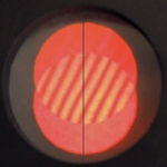
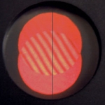
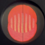
When collimating light, a shearing interferometer can be used to determine if a coherent beam of light is collimated. The interferometer is comprised of a wedged optical flat mounted at 45° and a diffuser plate with a ruled reference line down the middle.
The diffuser plate can then be used to view the interference fringes created by Fresnel reflections from the front and back surfaces of the optical flat (as shown in the images to the right). If the beam is collimated, the resulting fringe pattern will be parallel to the ruled reference line. In addition to the degree of collimation, the fringes will also be sensitive to spherical aberration, coma, and astigmatism.
Free-Space Coupling
When using our Large-Beam Achromatic Fiber Collimators as free-space couplers, precise alignment is needed for good coupling efficiency. In general, six movement degrees of freedom are recommended, such as pairing a kinematic mount with an XYZ translation stage. For example, the 20 mm or 40 mm collimators can be mounted with a KM100T, KC1-T (KC1-T/M), or KS1T kinematic mount and an MT3 (MT3/M) translation stage. The 80 mm collimators can be mounted using a KM200T, KC2T(/M), or KS2T kinematic mount and an MT3 (MT3/M) translation stage. The beam can be focused anywhere between the maximum waist distance (see the Divergence tab for details) and the closest focusing distance, enabling easy optimization of coupling efficiency. AR-coated single mode or polarization-maintaining patch cables can be used to further increase coupling efficiency and beam quality; these cables feature an AR coating on one connector end that improves return loss at the fiber-to-free-space interface when coupling.

Click to Enlarge
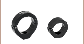
The red focusing ring provides smooth adjustment of the focusing distance.
Adjustment
Light collimated from a single mode fiber has a nearly Gaussian beam profile, with waist diameter and divergence angle depending on both the wavelength of light and the mode field diameter (MFD) of the fiber. When our Large-Beam Achromatic Fiber Collimators are adjusted so that they do not fully collimate the beam, the position of the beam waist will also exhibit sensitivity to the wavelength and MFD. In light of these application-specific dependencies, the ring has been engraved with the focusing distances obtained for light from a point source at the fiber tip location, using ray optics. These wavelength-independent values do not correspond to the waist locations for beams obtained from single mode fibers, so if the waist location is important for a given application then it should be determined in the particular setup.
Thorlabs' achromatic fiber collimators provide a fixed 20 mm, 40 mm, or 80 mm focal length to the fiber while allowing the beam to be focused between the maximum waist distance (see the Divergence tab) and the closest focusing distance. This allows for simple optimization of coupling efficiency from a free-space laser beam into a fiber.
To adjust the focusing distance, rotate the red section of the housing as shown in the image to the right; this will alter the focal point of the beam. There is a setscrew on one end for locking the focus which can be adjusted using the included 0.05" (1.3 mm) hex key.
Longitudinal Chromatic Aberration
When used within the specified operating wavelength range, these achromatic fiber collimators are designed to minimize the longitudinal chromatic aberration, also known as chromatic focal shift. This aberration occurs when the focal planes for different wavelengths of light are located at different distances from the same focusing optic.
The focal shift produced by these collimators when they are used to couple free-space collimated beams into fibers is shown in the graphs below. The theoretical deviation of the focal plane location from the nominal focal length is plotted over the operating wavelength range. The calculation was performed for each coating type at the available focal lengths (20 mm, 40 mm, and 80 mm).
Click to Enlarge
Click Here for Theoretical Data
The chromatic focal shift for the 400 - 650 nm achromatic fiber collimators. The blue-shaded region indicates the specified operating wavelength range of the collimator.

Click to Enlarge
Click Here for Theoretical Data
The chromatic focal shift for the 650 - 1050 nm achromatic fiber collimators. The blue-shaded region indicates the specified operating wavelength range of the collimator.

Click to Enlarge
Click Here for Theoretical Data
The chromatic focal shift for the 1050 - 1650 nm achromatic fiber collimators. The blue-shaded region indicates the specified operating wavelength range of the collimator.
When collimating light from single-mode fibers, our Large-Beam Achromatic Fiber Collimators produce beams with large waist diameters and low divergence, making them usefully collimated over a long distance. The graphs below illustrate the theoretical 1/e2 beam diameter as a function of propagation distance for certain SM-coupled laser wavelengths using our achromatic fiber collimators, adjusted for minimum divergence by setting the focusing distance to infinity. The effect of changing the fiber or the wavelength can be estimated using the theoretical approximations below the graphs.

Click to Enlarge
Click Here for Theoretical Data
This data is calculated for SM600 single mode fiber and our large beam collimators for 400 - 650 nm.
Click to Enlarge
Click Here for Theoretical Data
This data is calculated for 780HP single mode fiber and our large beam collimators for 650 - 1050 nm.
Click to Enlarge
Click Here for Theoretical Data
This data is calculated for SMF-28-J9 single mode fiber and our large beam collimators for 1050 - 1650 nm.
Theoretical Approximation of the Divergence Angle
The divergence angle can be approximated theoretically using the formula below as long as the light emerging from the fiber has a Gaussian intensity profile. Consequently, the formula works well for single mode (SM) fibers, but will underestimate the divergence angle for multimode (MM) fibers since light emerging from a MM fiber typically has a non-Gaussian intensity profile.
The full divergence angle in degrees is approximated by
where MFD is the mode field diameter of the fiber and f is the focal length of the collimator. MFD and focal length must have the same units in this equation.
Example Calculation:
When the C40APC-A collimator is used with the P3-460B-FC-1 SM patch cable, MFD = 3.6 µm, f ≈ 40 mm, and λ = 543 nm, the divergence angle is:
θ ≈ (0.0036 mm / 40 mm) x (180 / 3.1416) ≈ 0.0051° or 0.089 mrad.
Theoretical Approximation of the Output Beam Diameter
The 1/e2 output beam diameter at the front focal plane of the collimator, when the collimator is set to minimize divergence, can be found using the approximation
where λ is the wavelength of light being used, MFD is the mode field diameter of the fiber, and f is the focal length of the collimator.
Example Calculation:
When the C80FC-C collimator (f = 80 mm) is used with the P1-SMF28E-FC-1 patch cable (MFD = 10.5 µm) at 1550 nm, the output beam diameter is:
d = 4 x 1550 nm x [80 mm / (3.1416 · 10.5 µm)] = 15.0 mm
Theoretical Approximation of the Maximum Waist Distance
For a given collimator, SM fiber, and wavelength of light, there is a maximum possible waist distance, which can be approximated by
where f is the focal length of the collimator, λ is the wavelength of light used, and MFD is the mode field diameter of the fiber.
Example Calculation:
When the C40FC-A collimator is used with the P3-460B-FC-1 SM patch cable, MFD = 3.6 µm, f = 40.0 mm, and λ = 543 nm, then the maximum waist distance is:
40 mm + (2 x (40 mm)2 x (543 nm) / (3.1416) x (3.6 µm)2) = 42.7 m.
Click to Enlarge
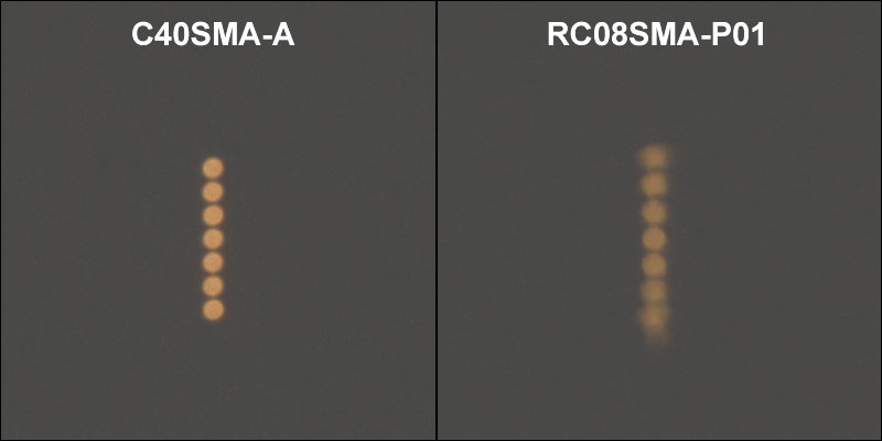
The picture above shows the image produced by the C40SMA-A Achromatic Fiber Collimator (left) and the RC08SMA-P01 Protected Silver Reflective Collimator (right) using a round-to-linear fiber bundle.

Click to Enlarge
The drawing above is an illustration of multimode fiber core image formation. The image is formed at the focusing distance determined by the adjustment ring.
Off-Axis Performance
Thorlabs' FC/PC- and SMA-terminated achromatic fiber collimators are excellent for use with multimode fibers. To demonstrate this feature, light from a halogen light source was collected with the round end of a BFL105LS02 Round-to-Linear Multimode Fiber Bundle. A C40SMA-A Achromatic Fiber Collimator and a reflective collimator were each used to image the output from the linear end onto a viewing screen placed approximately 0.35 m from the output, which is the closest focusing distance for the C40SMA-A collimator.
The image to the right demonstrates the C40SMA-A achromatic collimator’s excellent off-axis image performance for large multimode fiber cores, showing all 7 fiber cores in sharp, distinguishable focus. By contrast, the RC08SMA-P01 Reflective Collimator demonstrates significant off-axis aberrations (i.e. coma, astigmatism, and field curvature), when used with the same round-to-linear multimode fiber bundle. These aberrations result from the fact that parabolic mirrors do not perfectly collimate light from point sources located away from the focus of the paraboloid.
For large multimode fibers, our large-beam collimators also do not show significant vignetting (reduction of the image's intensity at its edges compared to at the center).
Imaging of Multimode Fiber Cores
When the focusing distance of the collimator is finite, an image of the multimode fiber core will be produced. The drawing to the right shows a ray optics picture of the formation of an image of a multimode fiber core. As the focusing distance of the collimator is changed, the size of the image will also change. The size of the image produced can be approximated with the following equation:
 .
.
The graphs below illustrate the theoretical imaged core diameter as a function of focusing distance using our SMA- or FC/PC-terminated achromatic fiber collimators. These results are independent of wavelength and connector type, but depend on the effective focal length of the collimator.

The graphs below show the reflectance with respect to the wavelength of the AR coatings used on the 8 lens surfaces in our achromatic fiber collimators (two surfaces per lens). The blue shaded region indicates the wavelength range specified for each coating. The table below details which AR coating is used with each collimator.

| Antireflection Coatings | |||||
|---|---|---|---|---|---|
| Item # Suffix | Wavelength Range | Reflectance (Per Surface)a | |||
| -A | 400 - 650 nmb | Rmax < 0.5% | |||
| -B | 650 - 1050 nm | Rmax < 0.5% | |||
| -C | 1050 - 1650 nm | Rmax < 0.5% | |||
| Damage Threshold Specifications | ||
|---|---|---|
| Item # Suffix | AR Coating | Damage Threshold |
| -A | 400 - 650 nm | 3 J/cm2 (532 nm, 10 Hz, 10 ns, Ø408 μm) |
| -B | 650 - 1050 nm | 7.5 J/cm2 (810 nm, 10 Hz, 10 ns, Ø76.9 μm) |
| -C | 1050 - 1650 nm | 3 J/cm2 (1542 nm, 1 Hz, 10 ns, Ø268 μm) |
Damage Threshold Data for Thorlabs' Achromatic Fiber Collimators
The specifications to the right are measured data for Thorlabs' Achromatic Fiber Collimators.
Laser Induced Damage Threshold Tutorial
The following is a general overview of how laser induced damage thresholds are measured and how the values may be utilized in determining the appropriateness of an optic for a given application. When choosing optics, it is important to understand the Laser Induced Damage Threshold (LIDT) of the optics being used. The LIDT for an optic greatly depends on the type of laser you are using. Continuous wave (CW) lasers typically cause damage from thermal effects (absorption either in the coating or in the substrate). Pulsed lasers, on the other hand, often strip electrons from the lattice structure of an optic before causing thermal damage. Note that the guideline presented here assumes room temperature operation and optics in new condition (i.e., within scratch-dig spec, surface free of contamination, etc.). Because dust or other particles on the surface of an optic can cause damage at lower thresholds, we recommend keeping surfaces clean and free of debris. For more information on cleaning optics, please see our Optics Cleaning tutorial.
Testing Method
Thorlabs' LIDT testing is done in compliance with ISO/DIS 11254 and ISO 21254 specifications.
First, a low-power/energy beam is directed to the optic under test. The optic is exposed in 10 locations to this laser beam for 30 seconds (CW) or for a number of pulses (pulse repetition frequency specified). After exposure, the optic is examined by a microscope (~100X magnification) for any visible damage. The number of locations that are damaged at a particular power/energy level is recorded. Next, the power/energy is either increased or decreased and the optic is exposed at 10 new locations. This process is repeated until damage is observed. The damage threshold is then assigned to be the highest power/energy that the optic can withstand without causing damage. A histogram such as that below represents the testing of one BB1-E02 mirror.

The photograph above is a protected aluminum-coated mirror after LIDT testing. In this particular test, it handled 0.43 J/cm2 (1064 nm, 10 ns pulse, 10 Hz, Ø1.000 mm) before damage.

| Example Test Data | |||
|---|---|---|---|
| Fluence | # of Tested Locations | Locations with Damage | Locations Without Damage |
| 1.50 J/cm2 | 10 | 0 | 10 |
| 1.75 J/cm2 | 10 | 0 | 10 |
| 2.00 J/cm2 | 10 | 0 | 10 |
| 2.25 J/cm2 | 10 | 1 | 9 |
| 3.00 J/cm2 | 10 | 1 | 9 |
| 5.00 J/cm2 | 10 | 9 | 1 |
According to the test, the damage threshold of the mirror was 2.00 J/cm2 (532 nm, 10 ns pulse, 10 Hz, Ø0.803 mm). Please keep in mind that these tests are performed on clean optics, as dirt and contamination can significantly lower the damage threshold of a component. While the test results are only representative of one coating run, Thorlabs specifies damage threshold values that account for coating variances.
Continuous Wave and Long-Pulse Lasers
When an optic is damaged by a continuous wave (CW) laser, it is usually due to the melting of the surface as a result of absorbing the laser's energy or damage to the optical coating (antireflection) [1]. Pulsed lasers with pulse lengths longer than 1 µs can be treated as CW lasers for LIDT discussions.
When pulse lengths are between 1 ns and 1 µs, laser-induced damage can occur either because of absorption or a dielectric breakdown (therefore, a user must check both CW and pulsed LIDT). Absorption is either due to an intrinsic property of the optic or due to surface irregularities; thus LIDT values are only valid for optics meeting or exceeding the surface quality specifications given by a manufacturer. While many optics can handle high power CW lasers, cemented (e.g., achromatic doublets) or highly absorptive (e.g., ND filters) optics tend to have lower CW damage thresholds. These lower thresholds are due to absorption or scattering in the cement or metal coating.

LIDT in linear power density vs. pulse length and spot size. For long pulses to CW, linear power density becomes a constant with spot size. This graph was obtained from [1].

Pulsed lasers with high pulse repetition frequencies (PRF) may behave similarly to CW beams. Unfortunately, this is highly dependent on factors such as absorption and thermal diffusivity, so there is no reliable method for determining when a high PRF laser will damage an optic due to thermal effects. For beams with a high PRF both the average and peak powers must be compared to the equivalent CW power. Additionally, for highly transparent materials, there is little to no drop in the LIDT with increasing PRF.
In order to use the specified CW damage threshold of an optic, it is necessary to know the following:
- Wavelength of your laser
- Beam diameter of your beam (1/e2)
- Approximate intensity profile of your beam (e.g., Gaussian)
- Linear power density of your beam (total power divided by 1/e2 beam diameter)
Thorlabs expresses LIDT for CW lasers as a linear power density measured in W/cm. In this regime, the LIDT given as a linear power density can be applied to any beam diameter; one does not need to compute an adjusted LIDT to adjust for changes in spot size, as demonstrated by the graph to the right. Average linear power density can be calculated using the equation below.

The calculation above assumes a uniform beam intensity profile. You must now consider hotspots in the beam or other non-uniform intensity profiles and roughly calculate a maximum power density. For reference, a Gaussian beam typically has a maximum power density that is twice that of the uniform beam (see lower right).
Now compare the maximum power density to that which is specified as the LIDT for the optic. If the optic was tested at a wavelength other than your operating wavelength, the damage threshold must be scaled appropriately. A good rule of thumb is that the damage threshold has a linear relationship with wavelength such that as you move to shorter wavelengths, the damage threshold decreases (i.e., a LIDT of 10 W/cm at 1310 nm scales to 5 W/cm at 655 nm):

While this rule of thumb provides a general trend, it is not a quantitative analysis of LIDT vs wavelength. In CW applications, for instance, damage scales more strongly with absorption in the coating and substrate, which does not necessarily scale well with wavelength. While the above procedure provides a good rule of thumb for LIDT values, please contact Tech Support if your wavelength is different from the specified LIDT wavelength. If your power density is less than the adjusted LIDT of the optic, then the optic should work for your application.
Please note that we have a buffer built in between the specified damage thresholds online and the tests which we have done, which accommodates variation between batches. Upon request, we can provide individual test information and a testing certificate. The damage analysis will be carried out on a similar optic (customer's optic will not be damaged). Testing may result in additional costs or lead times. Contact Tech Support for more information.
Pulsed Lasers
As previously stated, pulsed lasers typically induce a different type of damage to the optic than CW lasers. Pulsed lasers often do not heat the optic enough to damage it; instead, pulsed lasers produce strong electric fields capable of inducing dielectric breakdown in the material. Unfortunately, it can be very difficult to compare the LIDT specification of an optic to your laser. There are multiple regimes in which a pulsed laser can damage an optic and this is based on the laser's pulse length. The highlighted columns in the table below outline the relevant pulse lengths for our specified LIDT values.
Pulses shorter than 10-9 s cannot be compared to our specified LIDT values with much reliability. In this ultra-short-pulse regime various mechanics, such as multiphoton-avalanche ionization, take over as the predominate damage mechanism [2]. In contrast, pulses between 10-7 s and 10-4 s may cause damage to an optic either because of dielectric breakdown or thermal effects. This means that both CW and pulsed damage thresholds must be compared to the laser beam to determine whether the optic is suitable for your application.
| Pulse Duration | t < 10-9 s | 10-9 < t < 10-7 s | 10-7 < t < 10-4 s | t > 10-4 s |
|---|---|---|---|---|
| Damage Mechanism | Avalanche Ionization | Dielectric Breakdown | Dielectric Breakdown or Thermal | Thermal |
| Relevant Damage Specification | No Comparison (See Above) | Pulsed | Pulsed and CW | CW |
When comparing an LIDT specified for a pulsed laser to your laser, it is essential to know the following:

LIDT in energy density vs. pulse length and spot size. For short pulses, energy density becomes a constant with spot size. This graph was obtained from [1].
- Wavelength of your laser
- Energy density of your beam (total energy divided by 1/e2 area)
- Pulse length of your laser
- Pulse repetition frequency (prf) of your laser
- Beam diameter of your laser (1/e2 )
- Approximate intensity profile of your beam (e.g., Gaussian)
The energy density of your beam should be calculated in terms of J/cm2. The graph to the right shows why expressing the LIDT as an energy density provides the best metric for short pulse sources. In this regime, the LIDT given as an energy density can be applied to any beam diameter; one does not need to compute an adjusted LIDT to adjust for changes in spot size. This calculation assumes a uniform beam intensity profile. You must now adjust this energy density to account for hotspots or other nonuniform intensity profiles and roughly calculate a maximum energy density. For reference a Gaussian beam typically has a maximum energy density that is twice that of the 1/e2 beam.
Now compare the maximum energy density to that which is specified as the LIDT for the optic. If the optic was tested at a wavelength other than your operating wavelength, the damage threshold must be scaled appropriately [3]. A good rule of thumb is that the damage threshold has an inverse square root relationship with wavelength such that as you move to shorter wavelengths, the damage threshold decreases (i.e., a LIDT of 1 J/cm2 at 1064 nm scales to 0.7 J/cm2 at 532 nm):

You now have a wavelength-adjusted energy density, which you will use in the following step.
Beam diameter is also important to know when comparing damage thresholds. While the LIDT, when expressed in units of J/cm², scales independently of spot size; large beam sizes are more likely to illuminate a larger number of defects which can lead to greater variances in the LIDT [4]. For data presented here, a <1 mm beam size was used to measure the LIDT. For beams sizes greater than 5 mm, the LIDT (J/cm2) will not scale independently of beam diameter due to the larger size beam exposing more defects.
The pulse length must now be compensated for. The longer the pulse duration, the more energy the optic can handle. For pulse widths between 1 - 100 ns, an approximation is as follows:

Use this formula to calculate the Adjusted LIDT for an optic based on your pulse length. If your maximum energy density is less than this adjusted LIDT maximum energy density, then the optic should be suitable for your application. Keep in mind that this calculation is only used for pulses between 10-9 s and 10-7 s. For pulses between 10-7 s and 10-4 s, the CW LIDT must also be checked before deeming the optic appropriate for your application.
Please note that we have a buffer built in between the specified damage thresholds online and the tests which we have done, which accommodates variation between batches. Upon request, we can provide individual test information and a testing certificate. Contact Tech Support for more information.
[1] R. M. Wood, Optics and Laser Tech. 29, 517 (1998).
[2] Roger M. Wood, Laser-Induced Damage of Optical Materials (Institute of Physics Publishing, Philadelphia, PA, 2003).
[3] C. W. Carr et al., Phys. Rev. Lett. 91, 127402 (2003).
[4] N. Bloembergen, Appl. Opt. 12, 661 (1973).

In order to illustrate the process of determining whether a given laser system will damage an optic, a number of example calculations of laser induced damage threshold are given below. For assistance with performing similar calculations, we provide a spreadsheet calculator that can be downloaded by clicking the LIDT Calculator button. To use the calculator, enter the specified LIDT value of the optic under consideration and the relevant parameters of your laser system in the green boxes. The spreadsheet will then calculate a linear power density for CW and pulsed systems, as well as an energy density value for pulsed systems. These values are used to calculate adjusted, scaled LIDT values for the optics based on accepted scaling laws. This calculator assumes a Gaussian beam profile, so a correction factor must be introduced for other beam shapes (uniform, etc.). The LIDT scaling laws are determined from empirical relationships; their accuracy is not guaranteed. Remember that absorption by optics or coatings can significantly reduce LIDT in some spectral regions. These LIDT values are not valid for ultrashort pulses less than one nanosecond in duration.
Figure 71A A Gaussian beam profile has about twice the maximum intensity of a uniform beam profile.
CW Laser Example
Suppose that a CW laser system at 1319 nm produces a 0.5 W Gaussian beam that has a 1/e2 diameter of 10 mm. A naive calculation of the average linear power density of this beam would yield a value of 0.5 W/cm, given by the total power divided by the beam diameter:
However, the maximum power density of a Gaussian beam is about twice the maximum power density of a uniform beam, as shown in Figure 71A. Therefore, a more accurate determination of the maximum linear power density of the system is 1 W/cm.
An AC127-030-C achromatic doublet lens has a specified CW LIDT of 350 W/cm, as tested at 1550 nm. CW damage threshold values typically scale directly with the wavelength of the laser source, so this yields an adjusted LIDT value:
The adjusted LIDT value of 350 W/cm x (1319 nm / 1550 nm) = 298 W/cm is significantly higher than the calculated maximum linear power density of the laser system, so it would be safe to use this doublet lens for this application.
Pulsed Nanosecond Laser Example: Scaling for Different Pulse Durations
Suppose that a pulsed Nd:YAG laser system is frequency tripled to produce a 10 Hz output, consisting of 2 ns output pulses at 355 nm, each with 1 J of energy, in a Gaussian beam with a 1.9 cm beam diameter (1/e2). The average energy density of each pulse is found by dividing the pulse energy by the beam area:

As described above, the maximum energy density of a Gaussian beam is about twice the average energy density. So, the maximum energy density of this beam is ~0.7 J/cm2.
The energy density of the beam can be compared to the LIDT values of 1 J/cm2 and 3.5 J/cm2 for a BB1-E01 broadband dielectric mirror and an NB1-K08 Nd:YAG laser line mirror, respectively. Both of these LIDT values, while measured at 355 nm, were determined with a 10 ns pulsed laser at 10 Hz. Therefore, an adjustment must be applied for the shorter pulse duration of the system under consideration. As described on the previous tab, LIDT values in the nanosecond pulse regime scale with the square root of the laser pulse duration:
This adjustment factor results in LIDT values of 0.45 J/cm2 for the BB1-E01 broadband mirror and 1.6 J/cm2 for the Nd:YAG laser line mirror, which are to be compared with the 0.7 J/cm2 maximum energy density of the beam. While the broadband mirror would likely be damaged by the laser, the more specialized laser line mirror is appropriate for use with this system.
Pulsed Nanosecond Laser Example: Scaling for Different Wavelengths
Suppose that a pulsed laser system emits 10 ns pulses at 2.5 Hz, each with 100 mJ of energy at 1064 nm in a 16 mm diameter beam (1/e2) that must be attenuated with a neutral density filter. For a Gaussian output, these specifications result in a maximum energy density of 0.1 J/cm2. The damage threshold of an NDUV10A Ø25 mm, OD 1.0, reflective neutral density filter is 0.05 J/cm2 for 10 ns pulses at 355 nm, while the damage threshold of the similar NE10A absorptive filter is 10 J/cm2 for 10 ns pulses at 532 nm. As described on the previous tab, the LIDT value of an optic scales with the square root of the wavelength in the nanosecond pulse regime:
This scaling gives adjusted LIDT values of 0.08 J/cm2 for the reflective filter and 14 J/cm2 for the absorptive filter. In this case, the absorptive filter is the best choice in order to avoid optical damage.
Pulsed Microsecond Laser Example
Consider a laser system that produces 1 µs pulses, each containing 150 µJ of energy at a repetition rate of 50 kHz, resulting in a relatively high duty cycle of 5%. This system falls somewhere between the regimes of CW and pulsed laser induced damage, and could potentially damage an optic by mechanisms associated with either regime. As a result, both CW and pulsed LIDT values must be compared to the properties of the laser system to ensure safe operation.
If this relatively long-pulse laser emits a Gaussian 12.7 mm diameter beam (1/e2) at 980 nm, then the resulting output has a linear power density of 5.9 W/cm and an energy density of 1.2 x 10⁻⁴ J/cm2 per pulse. This can be compared to the LIDT values for a WPQ10E-980 polymer zero-order quarter-wave plate, which are 5 W/cm for CW radiation at 810 nm and 5 J/cm2 for a 10 ns pulse at 810 nm. As before, the CW LIDT of the optic scales linearly with the laser wavelength, resulting in an adjusted CW value of 6 W/cm at 980 nm. On the other hand, the pulsed LIDT scales with the square root of the laser wavelength and the square root of the pulse duration, resulting in an adjusted value of 55 J/cm2 for a 1 µs pulse at 980 nm. The pulsed LIDT of the optic is significantly greater than the energy density of the laser pulse, so individual pulses will not damage the wave plate. However, the large average linear power density of the laser system may cause thermal damage to the optic, much like a high-power CW beam.

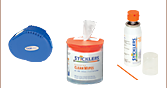
Click to Enlarge
Old Collimator Packaging
Click to Enlarge
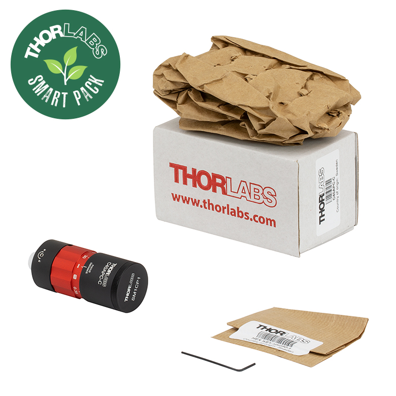
New Collimator Packaging
Smart Pack Goals
- Reduce Weight of Packaging
- Increase Usage of Recyclable Materials
- Improve Packing Integrity
- Decrease Shipping Costs
Thorlabs' Smart Pack Initiative is aimed at minimizing waste while providing adequate protection for our products. By eliminating any unnecessary packaging, implementing design changes, and utilizing eco-friendly materials, this initiative seeks to reduce the environmental impact of our product packaging.
The new large-beam fiber collimator packaging is made from compostable, 100% recycled paper products. The transition from plastic bags and styrofoam to recycled paper results in a 29.68% reduction in the amount of CO2 produced per kg of packing materials. All products on this page have transitioned or are in the process of transitioning to recycled paper.
As we move through our product line, we will indicate re-engineered, eco-friendly packaging with our Smart Pack logo, which can be seen in the image to the right.

Insights into Beam Characterization
Scroll down to read about:
- Beam Size Measurement Using a Chopper Wheel
Click here for more insights into lab practices and equipment.
Beam Size Measurement Using a Chopper Wheel
Click to Enlarge
Figure 2: The blade traces an arc length of Rθ through the center of the beam and has an angular rotation rate of  f. The chopper wheel shown is MC1F2.
Click to Enlarge
Figure 1: An approximate measurement of beam size can be found using the illustrated setup. As the blade of the chopper wheel passes through the beam, an S-curve is traced out on the oscilloscope.
Click to Enlarge
Figure 4: The diameter of a Gaussian beam is often given in terms of the 1/e2 full width.

Click to Enlarge
Figure 3: Rise time (tr ) of the intensity signal is typically measured between the 10% and 90% points on the curve. The rise time depends on the wheel's rotation rate and the beam diameter.
Camera and scanning-slit beam profilers are tools for characterizing beam size and shape, but these instruments cannot provide an accurate measurement if the beam size is too small or the wavelength is outside of the operating range.
A chopper wheel, photodetector, and oscilloscope can provide an approximate measurement of the beam size (Figure 1). As the rotating chopper wheel's blade passes through the beam, an S-shaped trace is displayed on the oscilloscope.
When the blade sweeps through the angle θ , the rise or fall time of the S-curve is proportional to the size of the beam along the direction of the blade's travel (Figure 2). A point on the blade located a distance R from the center of the wheel sweeps through an arc length (Rθ ) that is approximately equal to the size of the beam along this direction.
To make this beam size measurement, the combined response of the detector and oscilloscope should be much faster than the signal's rate of change.
Example: S-Curve with Rising Edge
The angle ftr )ftr )
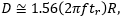
includes a factor of 1.56, which accounts for the portion of the beam measured between the 10% and 90% intensity points being smaller than the 1/e2 beam diameter.
Date of Last Edit: June 22, 2021
Content improved by our readers!
| Posted Comments: | |
user
(posted 2024-11-07 18:04:34.027) The divergence equation which is provided is only applied to the minimum divergence when the "FOCUS DISTANCE" is set to infinite. I would like to know how to calculate the divergence when the "FOCUS DISTANCE" is changed. Thank you. srydberg
(posted 2024-11-08 04:24:49.0) Hello, thank you for contacting Thorlabs! The divergence when the collimator is set to focusing can be simulated using the Zemax blackbox files that we provide on the website. I have contacted you to discuss your application. Anton Buchberger
(posted 2024-10-29 06:24:26.267) What is the operation temperature range of the C20FC-A? acanales
(posted 2024-10-29 10:28:06.0) Thank you for contacting us! We are using a 5-min epoxy for the collimators with the following temperature specs:
Long Term Exposure: -23°C to 49°C
Short Term Exposure:-23°C to 150°C user
(posted 2024-09-27 15:11:37.397) Dear Thorlabs Support,
I recently purchased two of your Achromatic Fiber Collimators with an adjustable focus and an effective focal length (EFL) to the fiber of 80 mm. In your website mentions that the focusing distance can be adjusted between infinity and the closest focusing point using the red ring in the housing.
I’m currently establishing a free-space optical link and want to predict its performance theoretically. By adjusting the focusing distance, does this affect the EFL, or does it alter another parameter? Should the EFL being left unaltered in my calculations?
Thank you for your help.
Best regards, srydberg
(posted 2024-10-03 03:27:36.0) Hi, thank you for contacting Thorlabs! The effective focal length of the C80 collimator is almost constant. Changing the red ring will change the output beam from a collimated beam at the infinity symbol to a convergent beam with a waist located in front of the collimator in a distance indicated on the scale of the collimator. Kim Minsu
(posted 2024-09-18 20:19:10.29) Dear Thorlabs Support Team,
I hope this message finds you well. My name is Minsu Kim, and I am a student at Chungbuk National University in South Korea, currently conducting research on free-space optical communication.
I am using SFP modules (BiDi) operating at 1490nm and 1550nm for my research over a distance of 50 meters. For the optical system, I am utilizing Thorlabs' C40FC-C lens. However, I have encountered an issue where automatic tracking is not feasible with this lens. To address this, I am planning to develop a system that enables automatic tracking using WDM, a beam splitter, and a photodiode.
I understand that the optical system is crucial in free-space optical communication, but as an electrical engineering major, my knowledge of optical systems is limited. Therefore, I would appreciate any technical advice you could provide on the following points:
1. Could you provide the specifications of the lens used in the C40FC-C? If this is not possible, is there a way to purchase the specific lens used in the C40FC-C?
2. Could you recommend an optimal lens for use at 50 meters with both 1490nm and 1550nm wavelengths?
3. I have set the beam diameter to 20mm when it hits the first lens after passing through free space. Is this a reasonable choice?
Thank you very much for your time and assistance. I look forward to your response.
Sincerely,
Minsu Kim
Student, Department of Electrical and Information Engineering
Chungbuk National University, South Korea acanales
(posted 2024-09-19 06:29:52.0) Thank you for reaching out to Thorlabs! We have contacted you directly to discuss your application. user
(posted 2024-07-08 12:40:27.637) What is the approximate M2 of your C20APC-A collimator? How does it compare to your triplet collimator series? acanales
(posted 2024-07-09 10:32:48.0) Thank you for contacting Thorlabs! The Large-Beam Achromatic Fiber Collimators are designed to the same specs as our Triplet Fiber Collimators and provide a superior beam quality. The benefits of the low-aberration optical design include a clean beam profile and an M2 term close to 1.0. WASIN LIMTHUNYALAK
(posted 2023-12-26 15:45:40.747) I can't download Drawing files with error message,
Access denied
Error 15
www.thorlabs.com
2023-12-26 06:44:26 UTC
What happened?
This request was blocked by our security service
Your IP: 61.7.192.202
Proxy IP: 45.60.119.153 (ID 101486-100)
Incident ID: 1486000680422688558-130436185486921991
Powered by
Imperva mkarlsson
(posted 2023-12-27 02:41:46.0) Thank you for reaching out! I've contacted you directly to provide you with the supporting files. user
(posted 2023-03-16 10:27:36.327) Is it possible to obtain focus at infinity for the C20xxxx model (the 20 mm focal length options) for the wavelength range of 635 nm to 1550 nm, or is the focus adjustment range insufficient to achieve this? Thank you fnero
(posted 2023-03-20 04:13:07.0) Thank you for reaching out. The C20APC-B can be collimated from 635 to 1550nm. The data can be extracted from the Zemax Black Box files we provide on the webpage.
The C20APC-C can be collimated from 1050nm and upwards. If the transmission of the C20APC-B is not sufficient for the application, a modified version can be discussed. For further discussions, please contact techsupport.se@thorlabs.com. user
(posted 2022-04-25 15:48:49.207) Are there some TYPO's in your information about the closest working distance for these adjustable focus (large beam) collimators ? eg for the F20 you state closest distance is 0.2 m. But that is 20 cm, not 20 mm. Just thought I'd let you know. jgreschler
(posted 2022-04-26 04:30:27.0) Thank you for reaching out to Thorlabs. To address your concern, the bullet point in question relates the focusing distance with the focal length of the lens system we used in the design, the two are not meant to be equal to each other. Pattabhi Dyta
(posted 2022-04-25 01:52:31.99) Hello, looking for telecentric and collimating lenses for spectrometers with SMA 905. Please suggest which category and appropriate models. We are looking for an online fruit sorting application. cdolbashian
(posted 2022-05-04 04:36:10.0) Thank you for reaching out to us with this inquiry. As this is more of an application-based inquiry, we have reached out to you directly to discuss potential components which will satisfy this application. For future similar inquiries, please contact us via techsupport@thorlabs.com Guillaume Blanquer
(posted 2021-11-23 07:41:48.07) Hello,
I would like to use an Achromatic collimator (C80SMA-B) to couple a polychromatic beam to an optical fiber with a NA of 0.5. Dans les spécifications, il est dit que le NA maximum du collimateur ne doit pas être supérieur à 0.25 NA. Dois-je tenir compte de la NA pour le couplage ?
Thank you in advance for your answer.
Guillaume YLohia
(posted 2021-11-23 03:25:42.0) Hello Guillaume, thank you for contacting Thorlabs. The 0.25 NA specified for collimating the output; if you have larger than 0.25NA fiber then you will overfill the aperture and, thus, get intensity loss. For coupling into a fiber, you can certainly use a 0.5 NA fiber, but you would not fill all of the modes of the fiber. Jonathan Twichell
(posted 2021-07-01 15:55:57.21) The data for visible, near IR etc are all bounded at the specified operating range. I need one to operate at 810 and 850, but would like to run a tag beam at 635. The data stops abruptly at 650 For many filters etc, you provide data beyond the designed operating range, sometimes by a lot. This is most appreciated. Sometimes coatings just fall apart at the edge, sometimes they just degrade. It looks like the 650 is for manufacturing tolerance but with modest penalty, it should be ok to 635. Data outside the designed wavelengths would be much appreciated YLohia
(posted 2021-07-09 03:05:24.0) The AR coating plots are supplied in the "Coatings" tab on this page. The raw data can be downloaded from our general Optical Coatings page here: https://www.thorlabs.com/newgrouppage9.cfm?objectgroup_id=5840&tabname=AR%20Coating. Viktor Dubec
(posted 2021-04-22 16:20:39.337) Hi, I think about using the C40SMA-A as a coupler. My TEM00 532nm beam diameter is 4mm. But high power, therefore I want to use MM fiber (perhaps ~400um). In order to not destroy the fiber with high power density, I plan to de-focus it with C40SMA-A. Question: what will be the maximum possible spot diameter of my beam at the fiber input? Thank you very much! mdiekmann
(posted 2021-04-29 08:29:20.0) Thank you for contacting us! We have reasched out directly to discuss your application in detail. 卢 尚
(posted 2021-04-22 19:15:10.67) Hello, we want to purchase two types of optical fiber collimators C40FC-A and ZC618FC-A. May I ask whether the order can be delivered first, and when can I ship the goods as soon as possible. We are more anxious here and want to use it by the end of May this year. YLohia
(posted 2021-04-22 11:08:29.0) Hello, questions on ordering our stock items can be directed to your local Thorlabs Sales Team (in your case, chinasales@thorlabs.com). We will reach out to you directly. 立恒 施
(posted 2020-05-12 12:17:10.617) 1. 关于调焦和束腰距离:请问调焦的话会改变束腰距离吗?根据网页上公式计算的最大束腰距离是不是通过调焦实现的?
2. 关于准直与耦合:根据网页上公式计算的准直光直径比器件口径要小不少,是否意味着将该准直器用于耦合器使用时,仅对该直径的入射光有最佳耦合效率?对于不同直径的空间入射光,其耦合效率变化大吗?
3. 关于自由空间耦合:作为耦合器时,该器件对入射高斯光束的六自由度姿态敏感程度是怎样的?比如说,我打算使用2个C40APC-C分别作为准直器和耦合器,使二者相距20m远,当耦合器的六自由度姿态发生变化时,对耦合效率的影响是怎样的? YLohia
(posted 2020-05-12 09:22:02.0) Thank you for contacting Thorlabs. An Applications Engineer from our team in China will reach out to you directly. kevin.yyw
(posted 2018-11-22 03:02:10.983) Dear Thorlabs team:
For this item of focuser, can we change the connector for SMA905?
We need it to do the fiber alingment, but we must use SMA905 connector, because our customer require select SMA905 connector fiber. YLohia
(posted 2018-12-03 12:20:32.0) Hello, thank you for contacting Thorlabs. Custom beam expanders can be requested through techsupport@thorlabs.com. I will reach out to you directly regarding the possibility of obtaining one of these. rkharrison
(posted 2018-07-25 12:23:26.577) Hi,
Can you make one of these with SMA fiber coupling?
Thanks,
Rick YLohia
(posted 2018-07-26 08:44:34.0) Hi Rick, I have reached out to you directly to discuss the possibility of offering this. user
(posted 2018-01-17 18:15:09.33) divergence calculation is wrong. Should be 0.089 mrad. tcampbell
(posted 2018-01-19 10:11:51.0) Hello, thank you for contacting Thorlabs. Our calculation already shows the result of 0.089 mrad. Feel free to contact us at techsupport@thorlabs.com if you have further questions about our calculations. |
Fiber Collimator Selection Guide
Click on the collimator type or photo to view more information about each type of collimator.
| Type | Description | |
|---|---|---|
| Fixed FC, APC, or SMA Fiber Collimators | 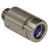 |
These fiber collimation packages are pre-aligned to collimate light from an FC/PC-, FC/APC-, or SMA-terminated fiber. Each collimation package is factory aligned to provide diffraction-limited performance for wavelengths ranging from 405 nm to 4.55 µm. Although it is possible to use the collimator at detuned wavelengths, they will only perform optimally at the design wavelength due to chromatic aberration, which causes the effective focal length of the aspheric lens to have a wavelength dependence. |
| Air-Spaced Doublet, Large Beam Collimators | 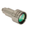 |
For large beam diameters (Ø5.3 - Ø8.5 mm), Thorlabs offers FC/APC, FC/PC, and SMA air-spaced doublet collimators. These collimation packages are pre-aligned at the factory to collimate a laser beam propagating from the tip of an FC or SMA-terminated fiber and provide diffraction-limited performance at the design wavelength. |
| Triplet Collimators | 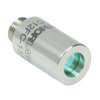 |
Thorlabs' High Quality Triplet Fiber Collimation packages use air-spaced triplet lenses that offer superior beam quality performance when compared to aspheric lens collimators. The benefits of the low-aberration triplet design include an M2 term closer to 1 (Gaussian), less divergence, and less wavefront error. |
| Achromatic Collimators for Multimode Fiber | 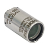 |
Thorlabs' High-NA Achromatic Collimators pair a meniscus lens with an achromatic doublet for high performance across the visible to near-infrared spectrum with low spherical aberration. Designed for use with high-NA multimode fiber, these collimators are ideal for Optogenetics and Fiber Photometry applications. |
| Reflective Collimators | 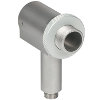 |
Thorlabs' metallic-coated Reflective Collimators are based on a 90° off-axis parabolic mirror. Mirrors, unlike lenses, have a focal length that remains constant over a broad wavelength range. Due to this intrinsic property, a parabolic mirror collimator does not need to be adjusted to accommodate various wavelengths of light, making them ideal for use with polychromatic light. Our fixed reflective collimators are recommended for collimating single and multimode fiber and coupling into multimode fiber. These collimators are available with UV-enhanced aluminum or protected silver reflective coatings and with FC/PC, FC/APC, or SMA connector compatibility. |
| Compact Reflective Collimators |  |
Thorlabs' Compact Reflective Collimators incorporate a 90° off-axis parabolic mirror with a protected silver coating. Because the focal length is independent of wavelength for an off-axis parabolic mirror, they are ideal for use with polychromatic light. Our fixed reflective collimators are recommended for collimating single and multimode fiber and coupling into multimode fiber. These collimators are directly compatible with our 16 mm cage system. They are available with FC/PC, FC/APC, or SMA connector inputs. |
| Adjustable Reflective Collimators | 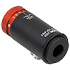 |
Thorlabs' Adjustable Focus Reflective Collimators use a 90° off-axis parabolic (OAP) mirror with a protected silver coating to collimate light from a fiber or couple light into a fiber. The adjustable fiber-to-OAP distance, combined with the OAP having a constant focal length across wavelengths, makes these collimators ideal for optimizing collimation or coupling of polychromatic light with single mode or multimode fiber. These adjustable collimators have a 15.0 mm or 33.0 mm reflected focal length and are available with FC/PC, FC/APC, or SMA connectors. |
| FiberPorts | 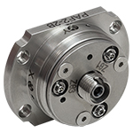 |
These compact, ultra-stable FiberPort micropositioners provide an easy-to-use, stable platform for coupling light into and out of FC/PC, FC/APC, or SMA terminated optical fibers. It can be used with single mode, multimode, or PM fibers and can be mounted onto a post, stage, platform, or laser. The built-in aspheric or achromatic lens is available with five different AR coatings and has five degrees of alignment adjustment (3 translational and 2 pitch). The compact size and long-term alignment stability make the FiberPort an ideal solution for fiber coupling, collimation, or incorporation into OEM systems. |
| Adjustable Fiber Collimators |  |
These collimators are designed to connect onto the end of an FC/PC, FC/APC, or SMA connector and contain an AR-coated aspheric lens. The distance between the aspheric lens and the tip of the fiber can be adjusted to compensate for focal length changes or to recollimate the beam at the wavelength and distance of interest. |
| Achromatic Fiber Collimators with Adjustable Focus | 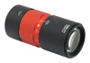 |
Thorlabs' Achromatic Fiber Collimators with Adjustable Focus are designed with an effective focal length (EFL) of 20 mm, 40 mm, or 80 mm, have optical elements broadband AR coated for one of three wavelength ranges, and are available with FC/PC, FC/APC, or SMA905 connectors. A four-element, air-spaced lens design produces superior beam quality (M2 close to 1) and less wavefront error when compared to aspheric lens collimators. These collimators can be used for free-space coupling into a fiber, collimation of output from a fiber, or in pairs for collimator-to-collimator coupling over long distances, which allows the beam to be manipulated prior to entering the second collimator. |
| Zoom Fiber Collimators | 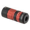 |
These collimators provide a variable focal length between 6 and 18 mm, while maintaining the collimation of the beam. As a result, the size of the beam can be changed without altering the collimation. This universal device saves time previously spent searching for the best suited fixed fiber collimator and has a very broad range of applications. They are offered with FC/PC, FC/APC, or SMA905 connectors with three different antireflection wavelength ranges to choose from. |
| Single Mode Pigtailed Collimators | 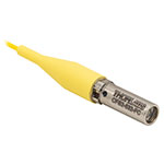 |
Our single mode pigtailed collimators come with one meter of fiber, consist of an AR-coated aspheric lens pre-aligned with respect to a fiber, and are collimated at one of eight wavelengths: 532 nm, 633 nm, 780 nm, 850 nm, 1030 nm, 1064 nm, 1310 nm, or 1550 nm. Although it is possible to use the collimator at any wavelength within the coating range, the coupling loss will increase as the wavelength is detuned from the design wavelength. |
| Polarization Maintaining Pigtailed Collimators | 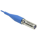 |
Our polarization maintaining pigtailed collimators come with one meter of fiber, consist of an AR-coated aspheric lens pre-aligned with respect to a fiber, and are collimated at one of five wavelengths: 633 nm, 780 nm, 980 nm, 1064 nm, or 1550 nm. Custom wavelengths and connectors are available as well. A line is engraved along the outside of the housing that is parallel to the fast axis. As such, it can be used as a reference when polarized light is launched accordingly. Although it is possible to use the collimator at any wavelength within the coating range, the coupling loss will increase as the wavelength is detuned from the design wavelength. |
| GRIN Fiber Collimators | 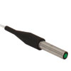 |
Thorlabs offers gradient index (GRIN) fiber collimators that are aligned at a variety of wavelengths from 630 to 1550 nm and have either FC terminated, APC terminated, or unterminated fibers. Our GRIN collimators feature a Ø1.8 mm clear aperture, are AR-coated to ensure low back reflection into the fiber, and are coupled to standard single mode or graded-index multimode fibers. |
| GRIN Lenses |  |
These graded-index (GRIN) lenses are AR coated for applications at 630, 830, 1060, 1300, or 1560 nm that require light to propagate through one fiber, then through a free-space optical system, and finally back into another fiber. They are also useful for coupling light from laser diodes into fibers, coupling the output of a fiber into a detector, or collimating laser light. Our GRIN lenses are designed to be used with our Pigtailed Glass Ferrules and GRIN/Ferrule sleeves. |
| Item # | EFLa | Typical Collimated Beam Diameterb,c |
Closest Focus Distance |
Clear Apertured |
Outer Diametere |
Threading | Connector | Transmission | AR Coating | Fiber NA (Max)f |
|---|---|---|---|---|---|---|---|---|---|---|
| C20FC-A | 20 mm | 3.8 mm (SM400 at 405 nm) 3.8 mm (SM450 at 543 nm) 3.8 mm (SM600 at 633 nm) |
0.2 m | Ø10.9 mm | 1.2" | Internal SM05 (0.035"-40) External SM1 (1.035"-40) |
2.2 mm FC/PC | 93% at 405 nm 93% at 543 nm 93% at 633 nm |
400 - 650 nm Rmax < 0.5% Per Surface |
0.25 |
| C20APC-A | 2.2 mm FC/APC | |||||||||
| C20SMA-A | SMA905 | |||||||||
| C40FC-A | 40 mm | 7.5 mm (SM400 at 405 nm) 7.4 mm (SM450 at 543 nm) 7.4 mm (SM600 at 633 nm) |
0.35 m | Ø20.5 mm | External SM1 (1.035"-40) |
2.2 mm FC/PC | ||||
| C40APC-A | 2.2 mm FC/APC | |||||||||
| C40SMA-A | SMA905 | |||||||||
| C80FC-A | 80 mm | 15.2 mm (SM400 at 405 nm) 14.9 mm (SM450 at 543 nm) 15.0 mm (SM600 at 633 nm) |
0.7 m | Ø42.5 mm | 2.2" | External SM2 (2.035"-40) |
2.2 mm FC/PC | |||
| C80APC-A | 2.2 mm FC/APC | |||||||||
| C80SMA-A | SMA905 |
| Item # | EFLa | Typical Collimated Beam Diameterb,c |
Closest Focus Distance |
Clear Apertured |
Outer Diametere |
Threading | Connector | Transmission | AR Coating | Fiber NA (Max)f |
|---|---|---|---|---|---|---|---|---|---|---|
| C20FC-B | 20 mm | 4.3 mm (780HP at 780 nm) 4.3 mm (SM980-5.8-125 at 980 nm) |
0.2 m | Ø10.9 mm | 1.2" | Internal SM05 (0.035"-40) External SM1 (1.035"-40) |
2.2 mm FC/PC | 96% at 780 nm 95% at 980 nm |
650 - 1050 nm Rmax < 0.5% Per Surface |
0.25 |
| C20APC-B | 2.2 mm FC/APC | |||||||||
| C20SMA-B | SMA905 | |||||||||
| C40FC-B | 40 mm | 8.6 mm (780HP at 780 nm) 8.6 mm (SM980-5.8-125 at 980 nm) |
0.35 m | Ø20.5 mm | External SM1 (1.035"-40) |
2.2 mm FC/PC | ||||
| C40APC-B | 2.2 mm FC/APC | |||||||||
| C40SMA-B | SMA905 | |||||||||
| C80FC-B | 80 mm | 17.3 mm (780HP at 780 nm) 17.2 mm (SM980-5.8-125 at 980 nm) |
0.7 m | Ø42.5 mm | 2.2" | External SM2 (2.035"-40) |
2.2 mm FC/PC | |||
| C80APC-B | 2.2 mm FC/APC | |||||||||
| C80SMA-B | SMA905 |
| Item # | EFLa | Typical Collimated Beam Diameterb,c |
Closest Focus Distance |
Clear Apertured |
Outer Diametere |
Threading | Connector | Transmission | AR Coating | Fiber NA (Max)f |
|---|---|---|---|---|---|---|---|---|---|---|
| C20FC-C | 20 mm | 4.4 mm (SM980-5.8-125 at 1064 nm) 3.6 mm (SMF-28-J9 at 1310 nm) 3.6 mm (SMF-28-J9 at 1550 nm) |
0.2 m | Ø10.9 mm | 1.2" | Internal SM05 (0.035"-40) External SM1 (1.035"-40) |
2.2 mm FC/PC | 92% at 1064 nm 92% at 1310 nm 92% at 1550 nm |
1050 - 1650 nm Rmax < 0.5% Per Surface |
0.25 |
| C20APC-C | 2.2 mm FC/APC | |||||||||
| C20SMA-C | SMA905 | |||||||||
| C40FC-C | 40 mm | 8.7 mm (SM980-5.8-125 at 1064 nm) 7.2 mm (SMF-28-J9 at 1310 nm) 7.3 mm (SMF-28-J9 at 1550 nm) |
0.35 m | Ø20.5 mm | External SM1 (1.035"-40) |
2.2 mm FC/PC | ||||
| C40APC-C | 2.2 mm FC/APC | |||||||||
| C40SMA-C | SMA905 | |||||||||
| C80FC-C | 80 mm | 17.5 mm (SM980-5.8-125 at 1064 nm) 14.5 mm (SMF-28-J9 at 1310 nm) 14.5 mm (SMF-28-J9 at 1550 nm) |
0.7 m | Ø42.5 mm | 2.2" | External SM2 (2.035"-40) |
2.2 mm FC/PC | |||
| C80APC-C | 2.2 mm FC/APC | |||||||||
| C80SMA-C | SMA905 |