 Products Home
Microscopy Slide and Test Target Holders
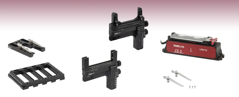
- Mount Microscope Slides, Filters, or Test Targets
- Fixed or Translating Slide Holder Options
- Slide Clips for Firmly Holding Samples in Place
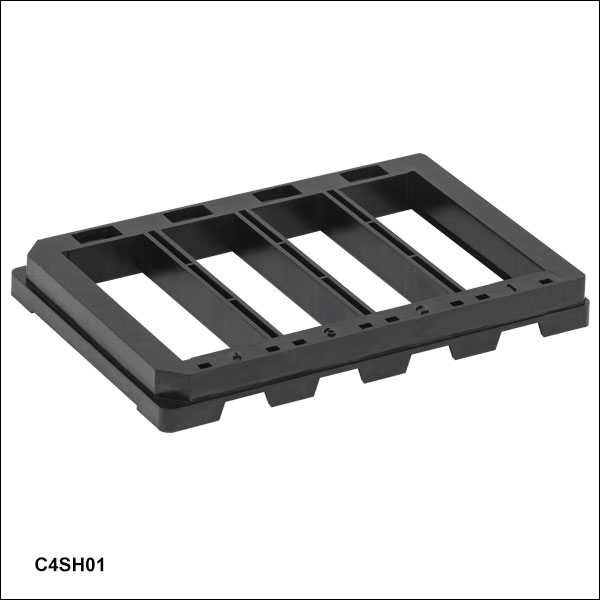
C4SH01
Multi-Slide Holder Tray
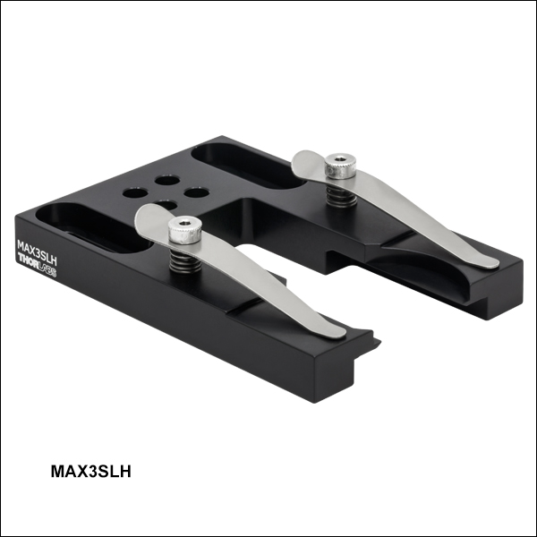
MAX3SLH
Fixed Microscope Slide Holder
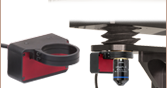
Application Idea
The LPSA1 slide holder with a microscope slide mounted on the LPS710 piezo stage.
SLH1
Microscope Slide Clips
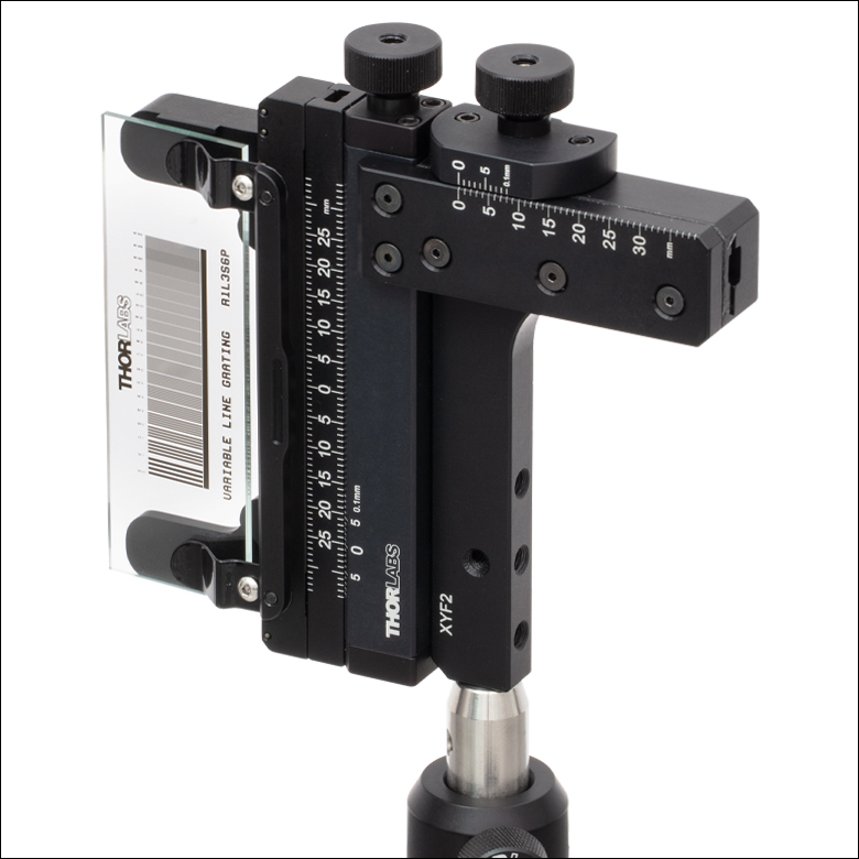
XYF2
XY Translation Mount
with Spring Clips
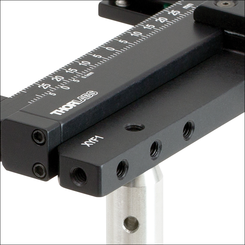
XYF1
XY Translation Mount
with Setscrews


Please Wait
Features
- Ideal for Mounting Rectangular Optics Such as Microscope Slides or Test Targets
- Fixed or Translating Versions
- Fixed Slide Holders for Mounting Single or Multiple Rectangular Optics
- Manual or Motorized Slide Holders with One- or Two-Axis Translation
- Versatile Mounting Arrangements
Fixed Microscope Slide Holders
Thorlabs offers two options for fixed microscope slide holders. The MAX3SLH fixed slide holder is compatible with microscope slides or test targets as well as any rectangular optic that has a minimum width of 1.73" (44.0 mm). It is directly compatible with our 3-axis flexure stages, as well as other translation stages that have 1/4"-20 (M6) taps on 2" (50.8 mm) centers. For mounting multiple microscope slides at once, we offer the C4SH01 slide holder, which supports up to four 25 mm x 75 mm, 1.1 ± 0.2 mm thick microscope slides per tray, enabling fast analysis of multiple cultures. It is directly compatible with any microscope stage insert that accepts standard multiwell microplates, such as Thorlabs’ Z-axis piezo stage, XY scanning stage (when the MLS203P1 plate adapter is also installed), or imaging cytometers. The C4SH01 slide holder is not compatible with the 26 mm x 76 mm slides sold by Thorlabs.
Translating Microscope Slide Holders
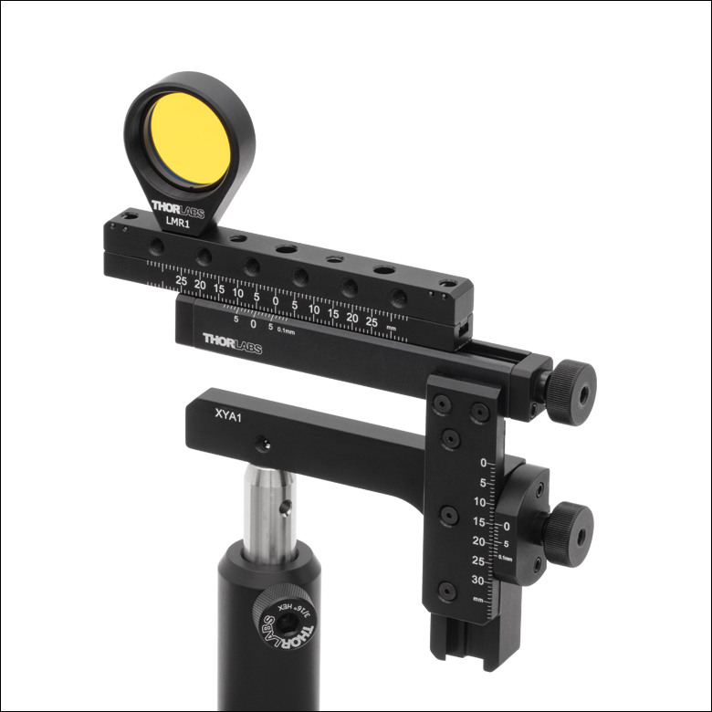
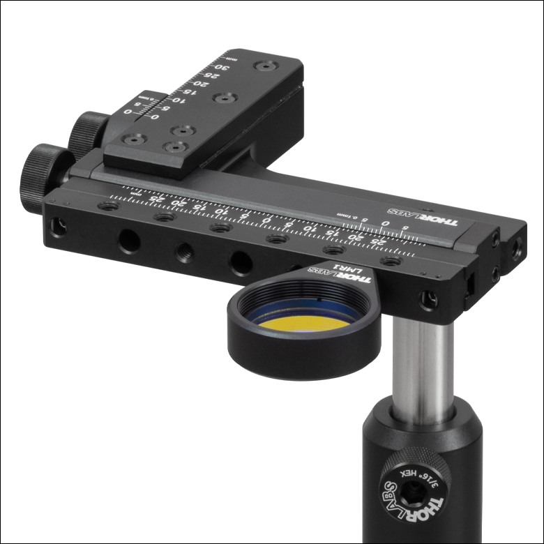
We offer two one-axis slide holders, the XF50(/M) for 50 mm translation and the XF100(/M) for 100 mm translation, as well two two-axis mounts (Item #s XYF1(/M) and XYF2(/M)). Both two-axis mounts provide translation over a 50 mm x 30 mm area. All translating microscope mounts are designed to provide stable, self-contained translation. The XF50(/M), XF100(/M), and XYF1(/M) mounts are ideal for mounting our microscope slides, test targets, filters, or any rectangular optic up to 126.2 mm (5") wide and 0.16" (4 mm) thick, while the XYF2(/M) accepts microscope slides and other optics between 2.95" (75.0 mm) to 3.03" (77.0 mm) wide, 0.98" (25.0 mm) to 3.03" (77.0 mm) tall, and 0.04" (1.0 mm) to 0.07" (1.7 mm) thick. For indirect mounting solutions utilizing fixed filter or optic mounts, the XYA1(/M) two-axis translation adapter also provides translation over a 50 mm x 30 mm area. Additionally, we have available the LPS710E(/M) amplified piezo stage with the LPSA1(/M) microscope slide holder; when used together, this stage and slide holder provide long range, fine focus Z-axis travel for a microscope slide while maintaining a compact, low-profile footprint. The LPSA1(/M) slide holder is compatible with microscope slides and test targets, as well as any rectangular optic from 2.88" (73.1 mm) to 3.00" (76.5 mm) wide and up to 0.055" (1.4 mm) thick and 1.00" (25.4 mm) tall.
Microscope Slide Spring Clips
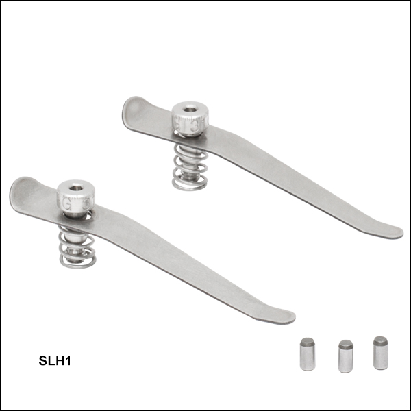
The SLH1(/M) microscope slide spring clips can be attached to any stage with 8-32 (M4) tapped holes to hold microscope slides or test targets of various sizes. Each clip is 2.51" (63.7 mm) long with a 0.20" (5.1 mm) wide tip and can be rotated 360° for easy access to slides. Three dowel pins are included to align slides over the central aperture of our XYR1(/M) and XYT1(/M) Translation Stages.
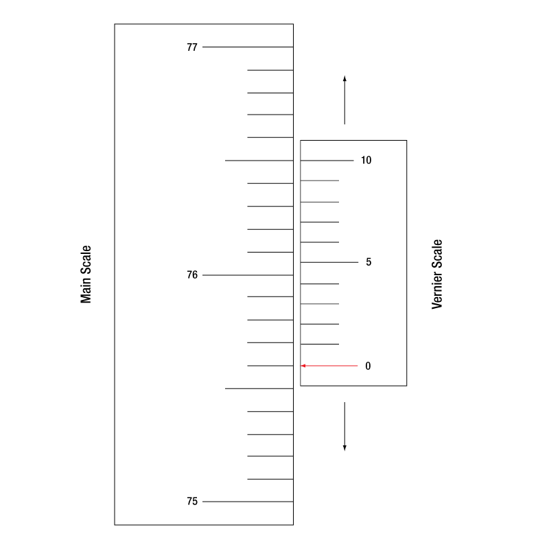
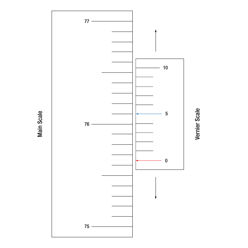
Reading a Vernier Scale on a Linear Main Scale
Vernier scales are typically used to add precision to standard, evenly divided scales (such as the scales on Thorlabs' rotation, goniometric, or translation mounts). A vernier scale has found common use in many precision measurement instruments, the most common being calipers and micrometers. The vernier scale uses two scales side-by-side: the main scale and the vernier scale. The direct vernier scale has a slightly smaller spacing between its tick marks owing to the vernier scale having N ticks for every N - 1 ticks on the main scale. Hence, the lines on the main scale will not line up with all the lines on the vernier scale. Only one line from the vernier scale will match well with one line of the main scale, and that is the trick to reading a vernier scale.
Figures 1 through 3 show a linear vernier scale system for three different situations. In each case, the scale on the left is the main scale, while the small scale on the right is the vernier scale. When reading a vernier scale, the main scale is used for the gross number, and the vernier scale gives the precision value. In this manner, a standard ruler or micrometer can become a precision instrument.
The 0 on the vernier scale is the "pointer" (marked by a red arrow in Figures 1 - 5) and will indicate the main scale reading. In Figure 1 we see the pointer is lined up directly with the 75.6 line. Notice that the only other vernier scale tick mark that lines up well with the main scale is 10. Since the pointer lines up with the main scale’s 75.6, the reading from Figure 1 is 75.60 (in whatever units the instrument measures).
That is essentially all there is to reading a vernier scale. It's a very straightforward way of increasing the precision of a measurement instrument. To expound, let’s look at Figure 2. Here we see that the pointer is no longer aligned with a line on the main scale, but instead it is slightly above 75.6 and below 75.7; thus, the gross measurement is 75.6. The first vernier line that coincides with a main scale line is the 5, shown with a blue arrow. The vernier scale gives the final digit of precision; since the 5 is aligned to the main scale, the precision measurement for Figure 2 is 75.65.
Since this vernier scale is 10% smaller than the main scale, moving the vernier scale by 1/10 of the main scale will align the next vernier marking. This asks the obvious question: what if the measurement is within the 1/10 precision of the vernier scale? Figure 3 shows just this. Again, the pointer line is in between 75.6 and 75.7, yielding the gross measurement of 75.6. If we look closely, we see that the vernier scale 7 (marked with a blue arrow) is very closely aligned to the main scale, giving a precision measurement of 75.67. However, the vernier scale 7 is very slightly above the main scale mark, and we can see that the vernier scale 8 (directly above 7) is slightly below its corresponding main scale mark. Hence, the scale on Figure 3 could be read as 75.673 ± 0.002. A reading error of about 0.002 would be appropriate for
this instrument.
Click to Enlarge
Figure 1: An example of how to read a vernier scale. The red arrow indicates what is known as the pointer. Since the tick mark labeled 10 on the vernier scale aligns with one of the tick marks on the main scale, this vernier scale is reading 75.60 (in whatever units the instrument measures).
Click to Enlarge
Figure 2: The red arrow indicates the pointer and the blue arrow indicates the vernier line that matches the main scale. This scale reads 75.65.

Click to Enlarge
Figure 3: The red arrow indicates the pointer, and the blue arrow indicates the vernier line that matches the main scale. This scale reads 75.67 but can be accurately read as
75.673 ± 0.002.
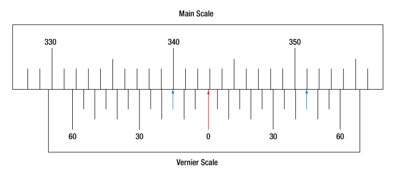
Reading a Vernier Scale on a Rotating Main Scale
The vernier scale may also be used on rotating scales where the main scale and vernier scale do not share units. Figures 4 and 5 show a vernier scale system for two different situations where the main scale is given in degrees and the vernier scale has ticks every 5 arcmin (60 arcmin = 1°). In each case, the scale on the top is the main scale, while the small scale on the bottom is the vernier scale.
In Figure 4 we see the pointer is lined up directly with the 341° line. Notice that the only other vernier scale tick marks that line up well with the main scale are ±60 arcmin. Since the pointer lines up with the main scale at 341°, the reading from Figure 4 is 341.00°.
There are two ways to determine the reading if the zero on the vernier scale line is between two lines of the main scale. For the first method, take the line on the left side of the pointer on the vernier scale and subtract that value (in arcmin) from the value on the main scale that is to the right on the main scale. As an example, in Figure 5 the vernier pointer is between 342° and 343°; using the left blue arrow of the vernier scale results in
As we've seen here, vernier scales add precision to a standard scale measurement. While it takes a bit of getting used to, with a little practice, reading these scales is fairly straightforward. Vernier scales, whether they are direct or retrograde*, are read in the same fashion.
*A retrograde vernier scale has a larger spacing between its tick marks with N ticks for every N + 1 ticks on the main scale.

Click to Enlarge
Figure 4: An example of a vernier scale where the main scale and the vernier scale are in different units (degrees and arcmins, respectively). The red arrow indicates the pointer. This scale reads 341.00°.
Click to Enlarge
Figure 5: The red arrow indicates the pointer and the blue arrows give the precision value from the vernier scale.
This scale reads 342.75°.
| Posted Comments: | |
ludoangot
(posted 2018-11-07 16:51:27.11) I have recently received the new XYF1 and also own the previous model. I find the new model to be stiffer to operate than the original (the actuators are stiffer). Also I feel a periodic resistance when rotating the horizontal axis actuator: that is to say, if one plotted the torque required to rotate the actuator vs distance traveled , the torque would follow a sine wave like pattern rather than be constant. In an attempt to improve the new model's operation I applied some grease on the lead screw and rack and pinion (the old model had grease, the new one not). This helped but didn't completely solve either issues. Could you please comment on the use of grease (a dry mechanism is a clear advantage as it prevents any contamination of the test target, but it has to be smooth), and is there anything I could adjust in order to improve operation? llamb
(posted 2018-11-09 09:24:00.0) Thank you for your feedback. This new XYF1 filter holder was designed to be greaseless to both prevent contamination of the test target and to also prevent exposed components from sticking over time. The design is naturally stiffer than the previous filter holder. If you see uneven rotation torque that inhibits your application, you can consider removing the brass translation locking screw and applying grease in the axle. Our mechanics team is now more closely monitoring the feel of these adjusters for future production. I will reach out to you directly to discuss further. cwong3
(posted 2018-10-11 13:49:50.037) Do you have any XYFM1 still in stock? I applied for funding to build a microscopy lab for the undergraduate class that I teach based on that model, and the new XYF1 is almost double in price and no longer fits in my budget. I only need one! I have a new lab discount, so I was counting on only spending $188 on this part. YLohia
(posted 2018-10-12 10:12:25.0) Hello, thank you for contacting Thorlabs. We are sorry to hear that the new XYF1 does not fit in your budget. We do still have a few units of the obsoleted item in our inventory. I will reach out to you via email with more information. mikael.malmstrom
(posted 2017-03-07 02:12:58.59) BEWARE! XYFM1 Translating Filter Mount does not work with the larger (100mm) ND filters as the image might fool you into thinking (https://www.thorlabs.com/newgrouppage9.cfm?objectgroup_id=1623)! tfrisch
(posted 2017-03-13 05:29:40.0) Hello, thank you for contacting Thorlabs. The maximum filter width for XYFM1 is 3" (76.2 mm). Please note that this is listed in the image caption, item name, and technical drawing. I will contact you directly about solutions for your application. user
(posted 2017-01-25 09:34:33.12) I second the idea (suggested below) of offering adapters for various cover slips sizes (especially 22 mm x 22 mm). tfrisch
(posted 2017-01-26 05:52:09.0) Hello, thank you for your feedback. I've posted your need in our internal engineering forum. If you have details on the dimensions of the slip, including thickness, please contact us directly at TechSupport@Thorlabs.com to discuss them. Thank you. mikael.malmstrom
(posted 2016-10-19 08:24:32.67) Hi can I put a Motorized Actuator on XYFM1/M one of the axes.
(I also vote for a slimmer version with only X translation) jlow
(posted 2016-10-24 03:05:58.0) Response from Jeremy at Thorlabs: Thank you for your feedback. Unfortunately we do not have a motorized actuator for the XYFM1(/M) at the moment. user
(posted 2016-09-22 14:11:35.207) Addition of a tapped hole on the back face of the mount would allow it to hold a microscope slide vertically like the xy stage can. jlow
(posted 2016-09-23 02:46:17.0) Response from Jeremy at Thorlabs: Thank you very much for your feedback. We will look into implementing this. loo
(posted 2016-02-05 15:05:09.033) Hi,
it would be nice if there was a bigger a more simple version of this product. Basically scrap the Y axis, make the X axis 100mm long and enlarge the optics bed to 25 x 100 x 4 mm, so we can fit a couple NDL-25C-4s. That's the setup I'been using for years, and it's annoying to order it to several companies every time I need one more. Also if the micrometric screw was easily motorizable it would be awesome. besembeson
(posted 2016-02-10 09:48:19.0) Response from Bweh at Thorlabs USA: Thanks for the feedback. We will review your suggestion. anthony.kaye
(posted 2014-04-07 09:10:24.09) A large number of our samples are small -- perhaps 10 mm x 10 mm; in some cases, we've had to cut them from larger substrates (so the edges aren't perfect). We would really like it if something like the XYFM1 could handle smaller (and/or oddly-shaped) samples. cdaly
(posted 2014-04-10 11:16:34.0) Response from Chris at Thorlabs: Unfortunately a 10 mm sample would be a bit too small for us to customize this mount for. The clamping fingers would end up covering the better part of the sample. Might it be possible to use the CH1A on a translation stage to hold your sample? ben_mangum
(posted 2013-05-15 16:51:51.62) It would be great if you could offer extra spring clips separately. Also, adapters allowing mounting of various sizes of coverslips would be great too. tcohen
(posted 2013-05-16 16:27:00.0) Response from Tim at Thorlabs: Thank you for sharing your idea. We’ll look into adapters and we can certainly provide the extra spring clips separately if desired. I will contact you directly to provide these. |

 Zoom
Zoom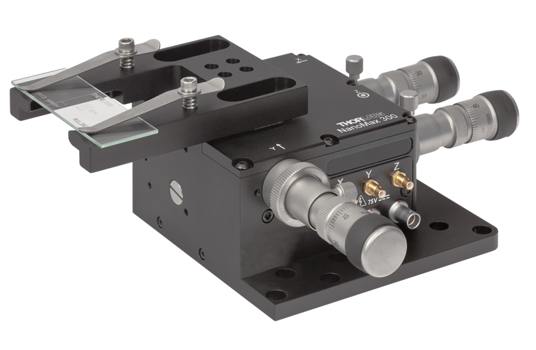
Click to Enlarge
The MAX3SLH Slide Holder can be Mounted Directly to our 3-Axis Nanopositioning Stage
- Compatible with
- Microscope Slides or ≥1.73" (44.0 mm) Wide Rectangular Optics
- Petri Dishes with Diameters from 1.46" (37.1 mm) to 1.63" (41.4 mm)
- Spring Clips Hold Sample Firmly in Place; Available Separately Below
- Mounts Directly to
- Our NanoMax, RollerBlock, and MicroBlock Flexure Stages
- Any Stage with 1/4"-20 (M6) Taps on 2" (50.8 mm) Centers
The MAX3SLH Microscopy Slide Holder allows petri dishes and microscope slides to be mounted on motion control stages for integration into custom microscopy setups such as optical tweezers. Two sets of mounting holes allow versatility. One set of four #6 (M3) counterbores is compatible with our 3-axis NanoMax flexure stages. A set of 1/4" (M6) slots with 2" (50.8 mm) separation is designed for mounting to many other components, including those with a 2" imperial hole pattern.
The spring clips are rotatable to accommodate easy swapping of petri dishes and microscope slides. There is a 1" long clear aperture between the mounting surfaces of the clips. They are also interchangeable with the SLH1 Microscope Slide Spring Clips sold below, as they both use 8-32 screws to secure them.

 Zoom
Zoom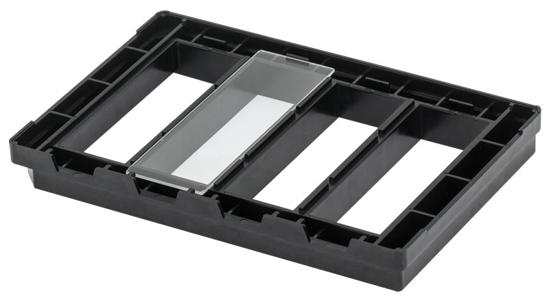
Click to Enlarge
Bottom of the C4SH01 Holder with Mounted Slide
- Compatible with 25 mm x 75 mm, 1.1 ± 0.2 mm Thick Microscope Slides
- Secures up to Four Slides and Requires Minimal Slide-to-Slide Focal Adjustments
- Mounts into Our Imaging Cytometers or on Our XY Scanning Stage
- Compatible with Most Common Robotic Plate Readers
The C4SH01 Four-Position Microscope Slide Holder, made from black PEI plastic, allows up to four 25 mm x 75 mm, 1.1 ± 0.2 mm thick slides to be mounted into our imaging cytometers or on microscope stages. Designed for inverted microscopes, this slide holder is highly versatile and adaptable for automated tissue analysis on multiple slides. As shown in the image to the right, slides are loaded into the bottom of the tray, ensuring excellent stability and maintaining near parfocality from slide to slide. This slide holder has the external footprint of a standard multiwell plate (127.6 mm × 85.5 mm), allowing it to be easily integrated into existing microscope stages (e.g., Thorlabs' MLS203 fitted with MLS203P1 or MZS500-E) or robotic plate loaders.
Note: The C4SH01 is not compatible with the 26 mm x 76 mm slides sold by Thorlabs.

 Zoom
Zoom
Click to Enlarge
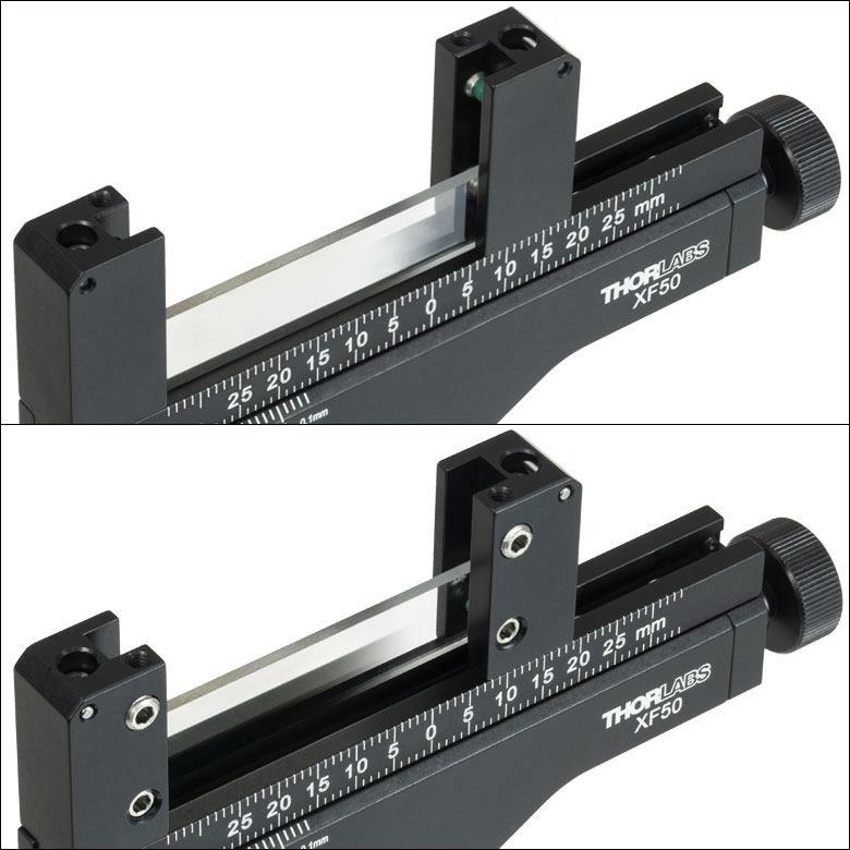
A channel allows for translation of the lockable support arms for accommodating optics with different widths.
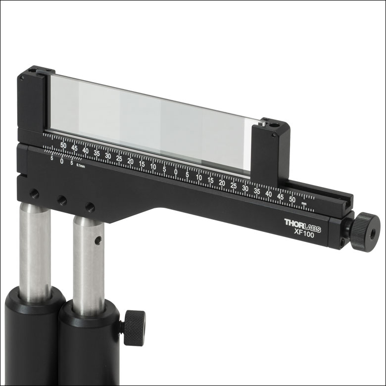
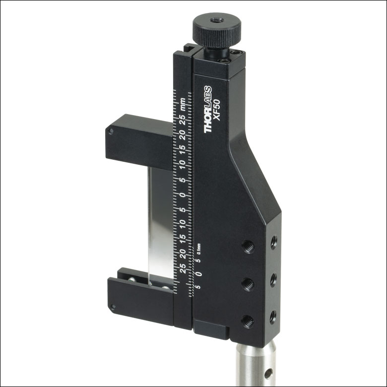
- Two Sizes Available:
- XF50(/M) Mounts Optics from 12.7 mm (0.50") to 76.2 mm (3.00") Wide
- XF100(/M) Mounts Optics from 12.7 mm (0.50") to 126.2 mm (4.97") Wide
- Maximum Optic Thickness of 4.0 mm (0.16")
- 50 mm or 100 mm Travel via Knurled Thumbscrew with 5/64" (2.0 mm) Hex
- Vernier Scale Provides 100 µm Resolution
- 8-32 (M4) Tapped Holes Support Several Post-Mounted Orientations
- Four Nylon-Tipped Setscrews Secure the Optic Between Two Mounting Arms
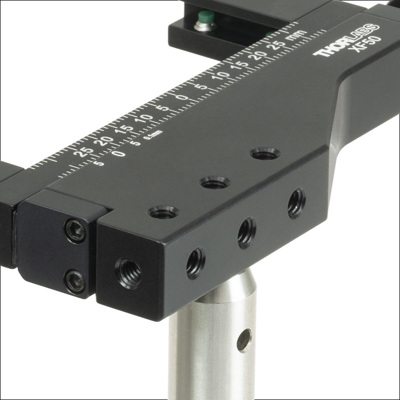
Thorlabs' One-Axis Rectangular Optic Mounts accept rectangular optics up to 4.0 mm (0.16") thick. The XF50(/M) offers 50 mm of travel and can mount optics from 12.7 mm (0.50") to 76.2 mm (3.00") wide. The XF100(/M) offers 100 mm of travel and can mount optics from 12.7 mm (0.50") to 126.2 mm (4.97") wide. These mounts are designed for use with our selection of resolution, distortion, slant edge, and calibration test targets. In addition, they are also compatible with our rectangular microscope slides, filters, dichroic mirrors, variable ND filters, and fluorescence imaging filters.
The actuator on the side of each mount enables travel along a single axis. The actuator can be adjusted by hand or with a 5/64" (2.0 mm) hex key (not included). A vernier scale that provides a resolution of 100 µm allows for repeatable positioning of the mounted optic. The actuator can be locked by a side-located 5/64" (2.0 mm) hex setscrew. Seven 8-32 (M4) tapped holes support several possible mounting orientations when used with our Ø1/2" posts. The three tapped holes along the front face of the mount are through holes allowing a post to be mounted on either side. Three of the mounting faces feature tapped holes spaced so that two Ø1/2" posts in post holders can be used next to each other for added stability.
Optics are secured with two support arms that each contain two nylon-tipped setscrews with a 5/64" (2.0 mm) hex. Each support arm can slide along a channel in the mount to accommodate different optic sizes; a 5/64" (2.0 mm) hex setscrew is used to lock each support arm in place. This mounting mechanism can be seen in the photo to the upper right. By loosening the top locking screws, the arms can be removed from the channel and interchanged, as shown in the image to the bottom left. When reattaching the arms, simply align each locking screw with one of the 2-56 captive nuts in the channel and tighten. This feature is useful in applications that require the target to be positioned close to a lens or other optical element in a system.
Please note that the support arms overlap the optic by 4.4 mm on each side.
Click for Details
The support arms can be removed from the channel and interchanged by loosening the locking screws.
Click to Enlarge
Each mount has seven 8-32 (M4) taps, allowing for several post-mountable orientations (see images to the right).
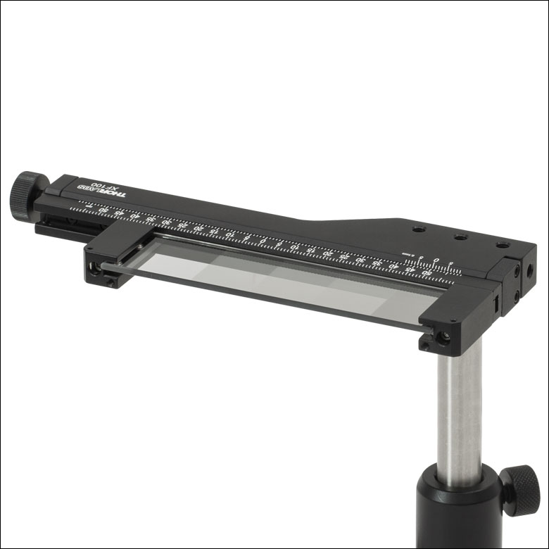
These Rectangular Optic Mounts can be used to position a rectangular optic horizontally, vertically, or perpendicular to the post axis and can be mounted using one or two posts.

 Zoom
Zoom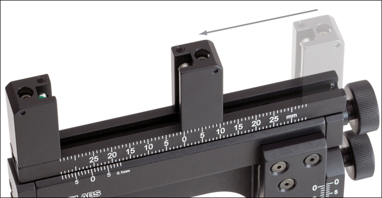
Click to Enlarge
A channel on the XYF1(/M) mount allows for translation of the lockable support arms for accommodating optics with different widths.
Click to Enlarge
The push bar on the XYF2(/M) mount moves the spring clips out to install a rectangular optic.
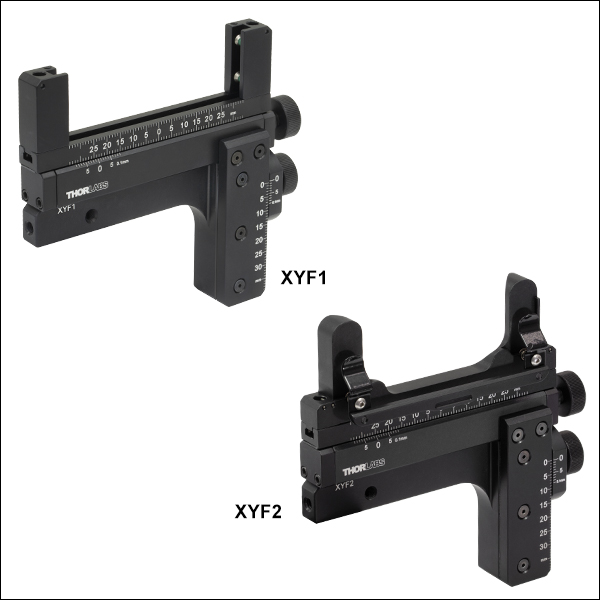
- Two Sizes Available:
- XYF1(/M): 1/2" (12.7 mm) to 3" (76.2 mm) Wide Rectangular Optics with a Max Thickness of 0.16" (4 mm)
- XYF2(/M): 2.95" (75.0 mm) to 3.03" (77.0 mm) Wide, 0.98" (25.0 mm) to 3.03" (77.0 mm) Tall Optics with a Thickness of 0.04" (1.0 mm) to 0.07" (1.7 mm)
- 50 mm (1.97") Horizontal Travel and 30 mm (1.18") Vertical Travel
- Each Axis Includes a Vernier Scale that Provides 100 µm Resolution
- 8-32 (M4) Tapped Holes Support Six Post-Mounted Orientations
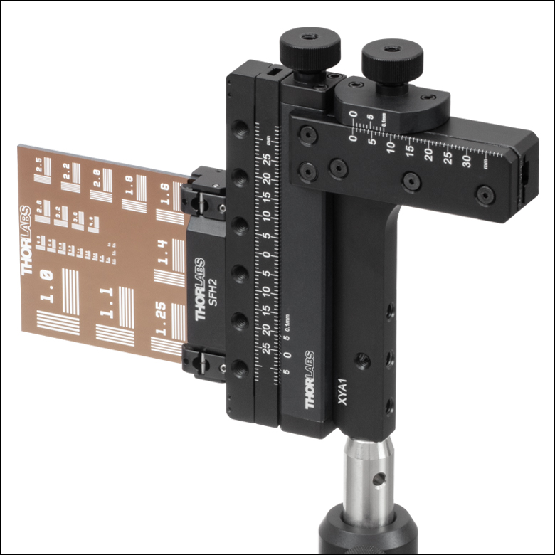
Thorlabs' XYF1(/M) Two-Axis Mount accepts a 1/2" (12.7 mm) to 3" (76.2 mm) wide rectangular optic up to 0.16" (4 mm) thick. The XYF2(/M) Two-Axis Mount accepts 2.95" (75.0 mm) to 3.03" (77.0 mm) wide, 0.98" (25.0 mm) to 3.03" (77.0 mm) tall, and 0.04" (1.0 mm) to 0.07" (1.7 mm) thick microscope slides and other optics. The mounts are ideal for general applications as well as home-built microscopy systems. The XYF1(/M) is designed for use with our selection of resolution, distortion, slant edge, and calibration test targets. In addition, it is also compatible with our rectangular microscope slides, filters, dichroic mirrors, variable ND filters, and fluorescence imaging filters. While the XYF2(/M) was designed for use with our microscope slides, it may also be used with a select range of resolution, distortion, and calibration test targets as well as filters and fluorescence imaging filters that do not exceed the size parameters. Alternatively, to accommodate other optic shapes and sizes, Thorlabs' XYA1(/M) translation adapter (available below) provides the same translation range as the XYF1(/M) and XYF2(/M) mounts, but features counterbores and threaded holes for mounting a fixed optic mount, such as a fixed filter holder.
Two actuator knobs on the side of each mount enable manual positioning over a 50 mm (1.97") x 30 mm (1.18") area, providing both vertical and horizontal translation. As an alternative to using the knobs, the actuators can also be adjusted using a 5/64" (2 mm) hex key or ball driver (not included). Next to each knob is a brass setscrew with a 5/64" (2 mm) hex for locking the translation axes, allowing for lockable, repeatable positioning of the mounted optic. Each mount is also equipped with a vernier scale that provides a resolution of 100 µm. Five 8-32 (M4) tapped holes support six possible mounting orientations when used with our Ø1/2" posts, of which a selection are shown below.
Optics are secured in the XYF1(/M) mount with two support arms that each contain two 5/64" (2 mm) hex, nylon-tipped setscrews. Each support arm can slide along a channel in the mount to accommodate different optic sizes; a 5/64" (2 mm) hex setscrew is used to lock each support arm in place. This mounting mechanism can be seen in the photo to the upper right. By loosening the top locking screws, the arms can be removed from the channel and reversed, as shown in the image to the bottom left. When reattaching the arms, simply align each locking screw with one of the 2-56 captive nuts in the channel and tighten. This feature is useful in applications that require the target to be positioned close to a lens or other optical element in a system. Please note that the support arms overlap the optic by 4.4 mm on each side.
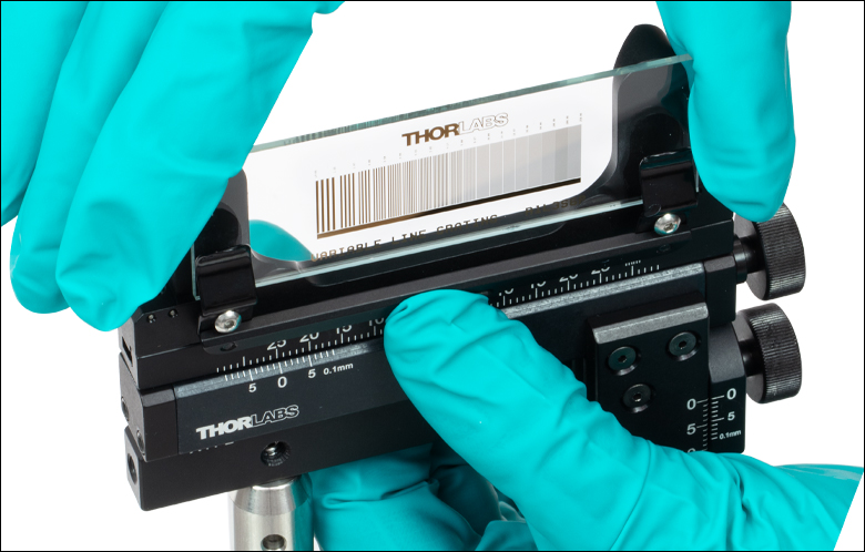
Optics are secured in the XYF2(/M) mount using two fixed spring clips. Please note that the distance between the two cannot be adjusted. To install a microscope slide in the XYF2(/M) mount, gently press on the push bar, lifting up the spring clips, and slide the optic in (see photo to the right). A 1.3 mm (0.05") hex setscrew below each spring clip allows fine adjustment of the distance between it and the back plate.

Click to Enlarge
The support arms on the XYF1(/M) mount can be removed from the channel and reversed by loosening the locking screws.
Click to Enlarge
The mounts have five 8-32 (M4) taps, allowing for six post-mountable orientations (see images to the right).
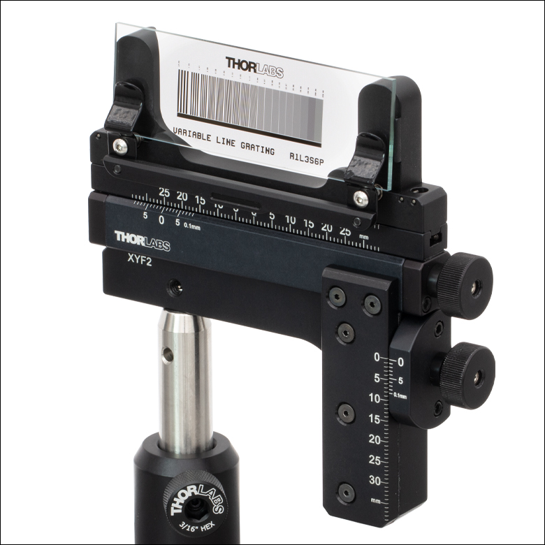
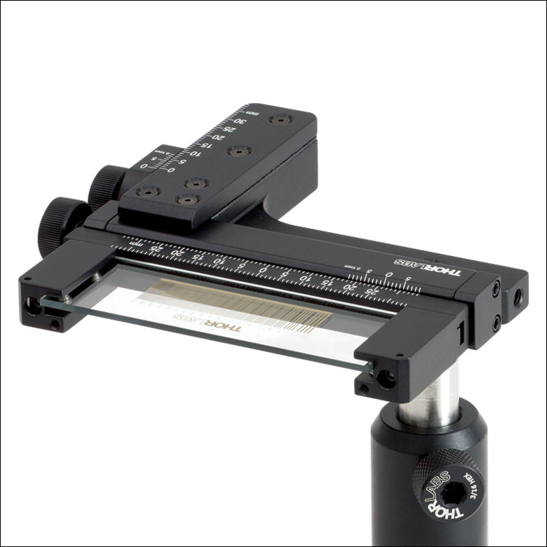
The XYF2(/M) (left and middle) and XYF1(/M) (right) mounts can be used to position a rectangular optic
(Item # R1L3S6P) horizontally, vertically, or perpendicular to the post axis.

 Zoom
Zoom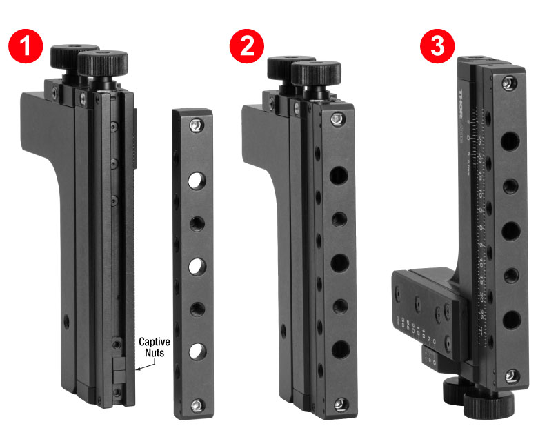
Click to Enlarge
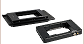
In order to secure an optic mount using the counterbores, the top bar needs to be removed. To reattach it, (1) tilt one end of the XYA1(/M) translation adapter downwards and allow both 2-56 captive nuts to slide to the bottom of the channel. (2) Align and tighten the bottom screw in the top bar. (3) Flip the translation adapter to allow the second 2-56 captive nut to slide to the bottom. Note that the nut will not be visible as it will be behind the partially attached top bar. The second screw can then be tightened and the top bar secured.
- XY Translation Over a 50 mm (1.97") x 30 mm (1.18") Area
- Removable Top Bar for Mounting Fixed Optic Mounts and Other Small Components
- Two 8-32 (M4 x 0.7) Tapped and Three #8 (M4) Counterbores in Top Surface
- Six 8-32 (M4 x 0.7) Tapped Through Holes on the Sides
- Supports Added Component Weight of <0.20 kg
- Each Axis Includes a Vernier Scale that Provides 100 µm Resolution
- Lockable Translation Axes for Repeatable Positioning
- Five 8-32 (M4) Tapped Holes for Mounting to Ø1/2" Posts
Thorlabs' XYA1(/M) Two-Axis Translation Adapter provides XY translation for fixed optic mounts (such as fixed lens, fixed mirror, and fixed filter mounts) and other small components that attach via an 8-32 (M4) tap or counterbore. The removable top bar features two 8-32 (M4 x 0.7) tapped holes and three #8 (M4) counterbored holes on the top, with six 8-32 (M4 x 0.7) tapped through holes on the sides. These features make the adapter ideal for general applications as well as home-built microscopy systems. For a version of this XY translation adapter that directly accepts rectangular optics, please see the XYF1(/M) Rectangular Optic Mount.
Two actuator knobs on the side of the mount enable manual positioning over a 50 mm (1.97") x 30 mm (1.18") area, which can be oriented either vertically or horizontally. These actuators can be adjusted by hand or with a 5/64" (2 mm) hex key or ball driver (not included). Next to each knob is a brass setscrew with a 5/64" (2 mm) hex for locking the traslation axes, allowing for lockable, repeatable positioning of the mounted component. This mount is also equipped with a vernier scale that provides a resolution of 100 µm; please see the Vernier Scales tab for more information. Five 8-32 (M4) tapped holes support several possible mounting orientations when used with our Ø1/2" posts, such that either translation axis can be oriented vertically or both axes can be oriented horizontally. A selection of possible mounting orientations is shown below.
The removable top bar is secured via two captive 5/64" (2 mm) hex setscrews which lock it in place. By loosening these locking screws, the top bar can be removed so that components can be mounted using the counterbored holes. To reattach the top bar, tip the adapter towards one end so that the 2-56 captive nuts in the top channel fall to one side. Replace the top bar and tighten the lower of the captive 5/64" (2 mm) hex setscrews. Then, tilt the adapter towards the other end and allow the second 2-56 captive nut to slide to that side of the adapter. The second locking screw can then be tightened, securing the top bar in place. This process can be seen in the image to the right.
Click to Enlarge
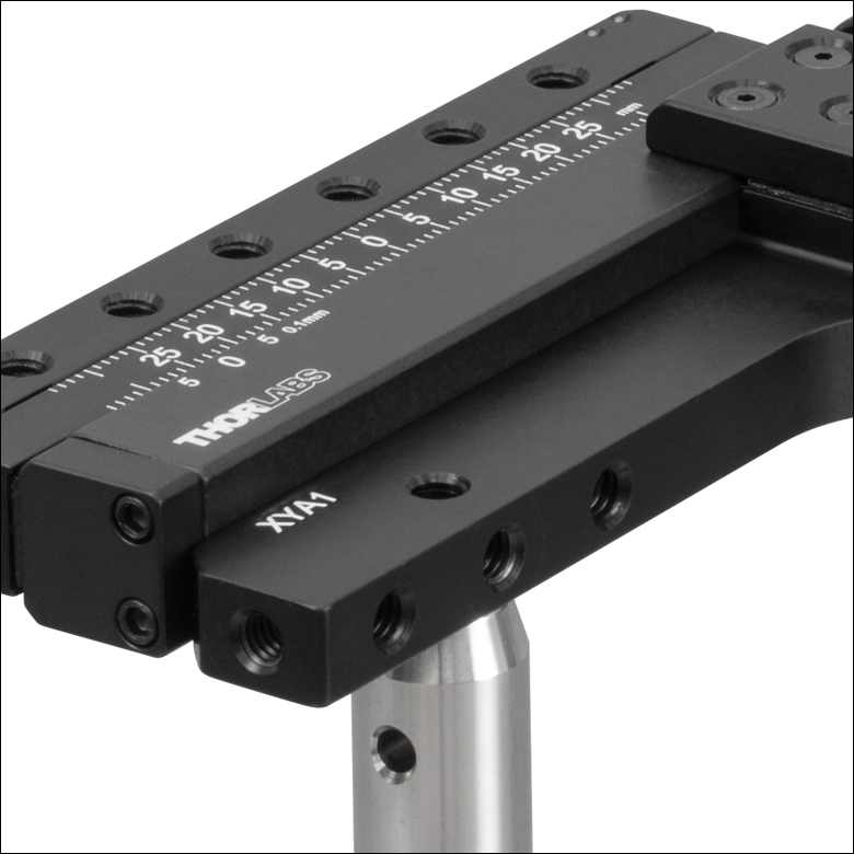
The XYA1 Adapter has five 8-32 (M4) taps, allowing for several post-mountable orientations (see images to the right for examples).
The XYA1 Adapter can be used in conjunction with fixed filter and lens mounts to position test targets, dichroic beamsplitters, and other optics. Either translation axis can be oriented vertically, or they can both be oriented horizontally.

 Zoom
Zoom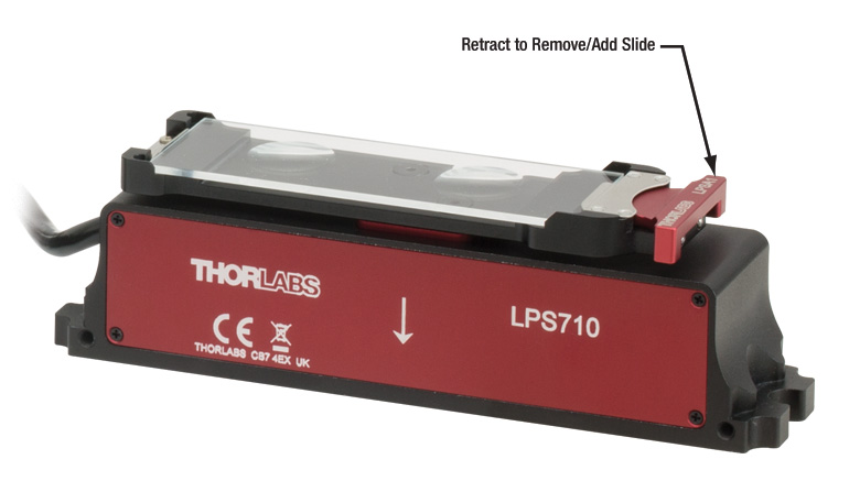
Click to Enlarge
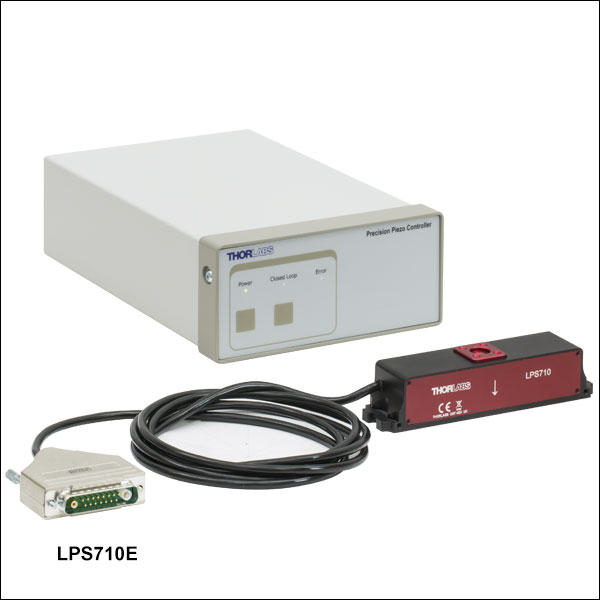
Once mounted onto the LPS710(/M) stage, secure a microscope slide onto the LPSA1(/M) holder using the spring-loaded plunger.
| LPS710E(/M) Key Specificationsa | ||
|---|---|---|
| Drive Voltage Range (Max) | -25 V to 150 V | |
| Travel | Open Loop | 1100 µm ± 10% |
| Closed Loop | 800 µm | |
| Resolution | Open Loop | 2 nm |
| Closed Loop | 6 nm | |
| Accuracy | Closed Loop | ±0.06% (Over Full Travel Range) |
| Bidirectional Repeatability | Closed Loop | ±0.03% (Over Full Travel Range) |
| Angular Error | Closed Loop | ±40 µrad (Over Full Travel Range) |
| Maximum Loadb | 300 g (0.66 lbs) | |
| Outer Dimensions (L x W x H) |
130 mm x 28 mm x 30 mm (5.1" x 1.1" x 1.2") |
|

- Slide Holder Compatible with 2.88" (73.1 mm) to 3.00" (76.5 mm) Wide Rectangular Optics
- Maximum Optic Thickness of 0.055" (1.4 mm)
- Piezo Stage Provides Long Range Z-Axis Motion; See Table for Details
- Mount Stage to Rigid Stands, Translating Platforms, or Directly to an Optical Table
- Kinesis® and APT™ Interfaces, ThorImage®LS Integration, and Control via External Voltage
- Click Here for the Full Web Presentation
The LPS710E(/M) Amplified Piezo Stage provides long range, fine focus Z-axis travel for a microscope slide while maintaining a compact, low-profile footprint. It features submicron repeatability, nanometer positioning resolution, low angular error, and fast millisecond response and settling times. Each stage is shipped with a piezo controller that has been factory calibrated to the specific stage to achieve maximum accuracy. When used with the LPSA1(/M) microscope slide holder, the stage is ideal for imaging modalities requiring sensitive sample positioning and sectioning, such as confocal laser scanning microscopy. This stage is not compatible with trans-illumination.
The stage is driven by a discrete piezo stack housed within a hardened steel flexure structure that preloads the piezo stack and amplifies its displacement. See the table to the right for key specifications. The base of the stage includes two slots for 1/4"-20 (M6) cap screws and two slots for 4-40 (M3) cap screws that can be used to secure the stage to a stage or breadboard for use with a microscope, such as our Rigid Stands or Translating Platforms, or directly to an optical table. In addition, the stage has two bottom- and side-located 4-40 (M3) mounting holes that can be used to secure the stage using our line of mini-series components.
The LPSA1(/M) slide holder uses two countersunk cap screws to attach to the 21.0 mm x 21.0 mm mounting surface on the top of the LPS710E(/M) stage. The mounting surface is equipped with four 4-40 (M3) blind mounting holes that are 4.8 mm deep to orient the slide holder in two orthogonal positions on the stage. The slide holder is compatible with microscope slides and test targets, as well as any rectangular optic from 2.88" (73.1 mm) to 3.00" (76.5 mm) wide and up to 0.055" (1.4 mm) thick and 1.00" (25.4 mm) tall. Slides are secured using the red, spring-loaded plunger, as shown in the image to the upper right.
More details on this piezo stage and microscope slide holder are available at their full web presentation.

 Zoom
Zoom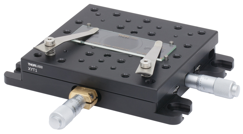
Click to Enlarge
SLH1 Spring Clips Attached to the XYT1 Translation Stage, Holding a Test Target That is Aligned Over the Central Aperture Using the Provided Dowel Pins
- Compatible with Microscope Slides and Test Targets of Various Sizes
- Attaches Directly to Any Stage with 8-32 (M4) Tapped Holes
- Dowel Pins Included for Aligning Standard Slides Over the Through Hole in Our XYR1(/M) or XYT1(/M) Translation Stages (See Photo to the Right)
These steel spring clips, which are ideal for securely holding various sizes of microscope slides and test targets, come with two 8-32 (M4) threaded shoulder screws, each of which has a 3/32" (2.5 mm) hex socket for simple attachment to a variety of stages. Each clip is 2.51" (63.7 mm) long with a 0.20" (5.1 mm) wide tip and can be rotated 360° for easy access to, or positioning of, a slide. The tip of the clip is curved upwards to help prevent damage and facilitate the mounting of slides, while also providing enough holding force to secure it in place.
The inclusion of three Ø1/8" x 1/4" dowel pins makes these spring clips an excellent choice for use with our XYR1(/M) and XYT1(/M) Translation Stages (see the image to the right). These stages have a central Ø1" hole that is SM1 threaded (1.035"-40), and the top plate contains three alignment holes that are used with the Ø1/8" dowel pins. The dowel pins are positioned on the stage so that standard 1" x 3" (25.4 mm x 76.2 mm) slides are centered over the aperture, allowing for repeatable and accurate positioning of the slides.
Please note that any XYR1(/M) stage purchased before June 4, 2014 does not have dowel pin holes in the top mounting plate.