 Products Home / Optical Elements / Test Targets, Calibration Targets, and Reticles / Resolution Test Targets
Resolution Test Targets
- Test Targets Identify Resolution of an Imaging System
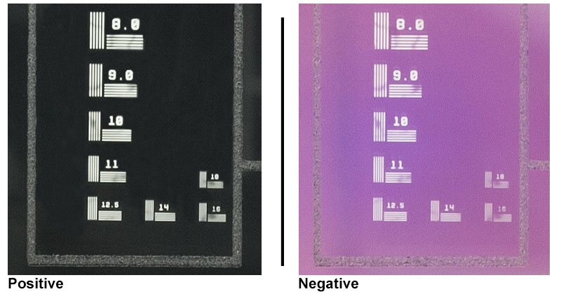
- Positive, Negative, or Birefringent Pattern
- Combined Resolution and Distortion Targets Available
R1DS1N
Ø1" 1951 USAF Target
R1L3S6PR
Reflective Variable Line Grating Target
R1L1S1P
Combined Resolution
and Distortion Target
R3L3S1N
Negative 1951 USAF Target
R1L1S2P
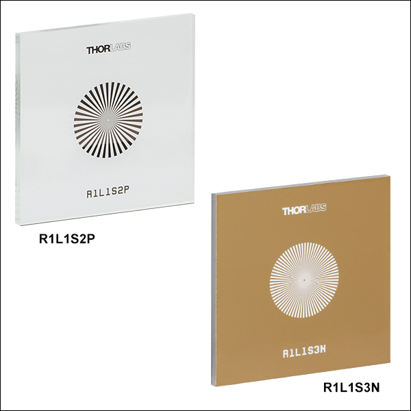
Sector Star Target
R2L2S1P1
Positive, High-Frequency
NBS 1963A Target


Please Wait
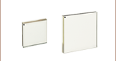
| Type | Photolithographic | Birefringent |
|---|---|---|
| Design | Chrome-on-Glass | Birefringent Pattern |
| Substrate | Clear Soda Lime Glassa | Variesb |
| Substrate Thickness | 0.06" (1.5 mm) | Variesb |
Quick Links
- 1951 USAF Resolution Test Targets, Ø1"
- 1951 USAF Resolution Test Targets, 1" x 1"
- 1951 USAF Resolution Test Targets, 1.5" x 1.5"
- 1951 USAF Resolution Test Targets, 3" x 1"
- 1951 USAF Birefringent Resolution Test Target, 3" x 1"
- 1951 USAF Resolution Test Targets, 3" x 3"
- NBS 1952 Resolution Test Target, 3" x 1"
- NBS 1952 Resolution Test Target, 3" x 3"
- NBS 1963A Resolution Test Targets, 2" x 2"
- High-Frequency NBS 1963A Resolution Test Targets, 2" x 2"
- NBS 1963A Birefringent Resolution Target, 2" x 2"
- Sector Star Targets, 1" x 1"
- Ronchi Ruling Targets, 3" x 1"
- Variable Line Grating, 3" x 1"
- Concentric Circles and Crosshairs Grid Target, 3" x 3"
- Combined Resolution and Distortion Test Targets, 18 mm x 18 mm
- Combined Resolution and Distortion Test Target, 3" x 1"
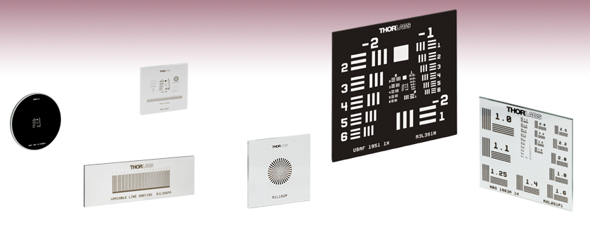
Resolution test targets are typically used to measure the resolution of an imaging system. They consist of reference line patterns with well-defined thicknesses and spacings and are designed to be placed in the same plane as the object being imaged. By identifying the largest set of non-distinguishable lines, one determines the resolving power of a given system. Thorlabs offers resolution test targets with 1951 USAF, NBS 1952, and NBS 1963A patterns. Targets are also available with sector star (also known as Siemens star) patterns, Ronchi rulings, a variable line grating, or a combination of patterns for resolution and distortion testing. For more information on each pattern, see the Resolution Targets tab.
All of our resolution test target patterns are manufactured using photolithography and available as positive targets; and many have negative versions as well. We also offer several versions of high-contrast positive reflective targets. The positive targets consist of low-reflectivity, vacuum-sputtered chrome patterns plated on clear substrates and are useful for front-lit and general applications. The negative targets use low-reflectivity chrome to cover the substrates, leaving the patterns clear, and work well in back-lit and highly illuminated applications. The positive reflective targets are composed of a low-reflectivity chrome pattern etched on soda lime glass with a chrome background for high contrast in reflective applications. See the Graphs tab for spectral data of the materials used in these test targets.
Mounting
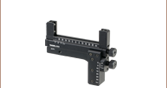
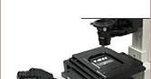
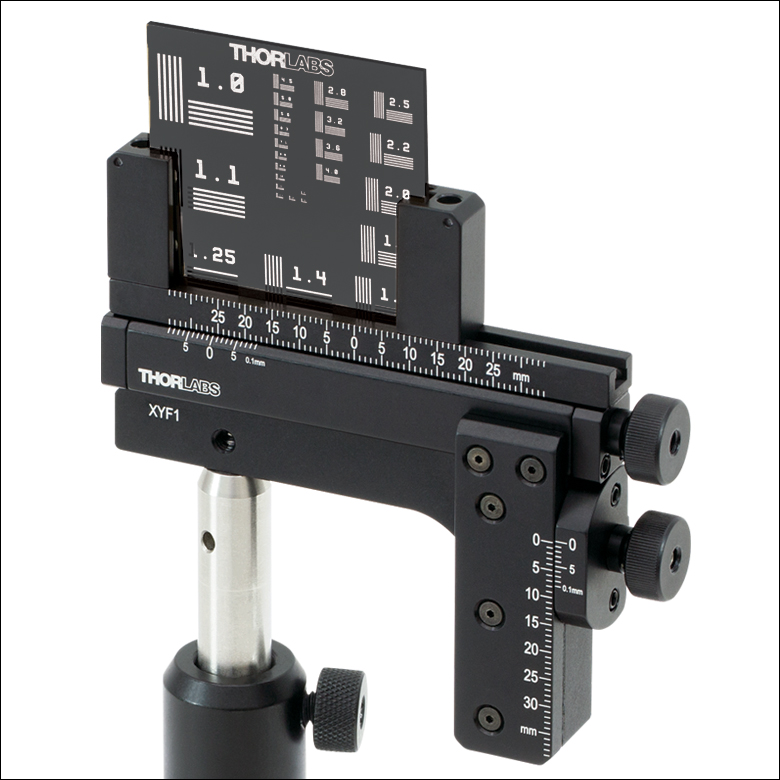
These resolution test targets can be mounted in one of four of our microscopy slide holders. Our MAX3SLH Fixed Slide Holder provides two spring clips to mount the optic and can be mounted to any of our 3-axis translation stages. The MAX3SLH is only compatible with test targets greater than or equal to 2" wide and provides a clear aperture of 1", which may cover the chrome pattern on some of the test targets. Thorlabs also offers our XYF1(/M) Test Target Positioning Mount (see photo to the right) capable of translating a 1" to 3" wide rectangular target over a 50 mm x 30 mm area. The mount offers five 8-32 (M4) taps for six post-mountable orientations. The XYF1(/M) mount uses nylon-tipped setscrews to secure the optic. Please note that the mount's support arms overlap the optic by 4.4 mm on each side. For users of our high-speed motorized XY scanning stages, we offer the MLS203P2 Slide Holder for Inverted Microscopes, which can mount slides 25 mm to 26.5 mm wide and petri dishes 30 mm to 60 mm in diameter.
Photolithographic Target Manufacturing
Our extensive production capabilities enable us to provide solutions for imaging system calibration and measurements. We use contact photolithography with a mask aligner to define the pattern on the glass substrate. Once the pattern is defined, we chemically etch the substrates and clean them in a class 100 cleanroom.
Birefringent Target Manufacturing
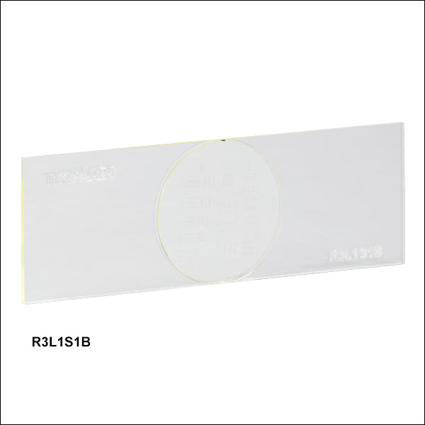
Our R3L1S1B and R2L2S1B Birefringent Resolution Targets have a pattern that is invisible unless viewed through a pair of crossed polarizers, making them ideal for calibration of polarization-sensitive systems. The pattern is created by using a photo alignment process to set the fast axis of the liquid crystal polymer layer, which is protected by two layers of glass. These devices are engineered so that the fast axis of the overall target is aligned parallel to the side of the glass covers, whereas the fast axis for the patterned area is aligned 45° to this edge. The entire targets have a retardation of 280 ± 20 nm. Additionally, they can display both positive and negative patterns by changing the orientation of the crossed polarizers. If the crossed polarizers are aligned with the sides of the target, the positive image will be formed. If the crossed polarizers are aligned at 45° to the sides of the target, the negative image will be formed.
Thorlabs also offers a complete line of reticles for superimposing a reference pattern onto an object.
| Targets Selection Guide | ||||
|---|---|---|---|---|
| Resolution Test Targets | Calibration Targets | Distortion Test Targets | Slant Edge MTF Target | Stage Micrometers |
Click to Enlarge
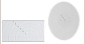
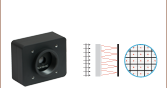
Line pairs help measure how well a camera can distinguish two objects from one another.
Imaging Resolution
The resolution of an imaging system is often specified in line pairs per millimeter (lp/mm), where a line pair is one light line and one dark line. This value represents the smallest distance between two objects that can be registered by the system; a higher value in lp/mm means the distance between each pair of lines is smaller.
The diagram to the right illustrates the resolution limit of a system. The line pair imaged by the camera on the left cannot be resolved; the two lines are registered by adjacent pixels on the camera sensor, causing them to appear as a single object. In contrast, the line pair on the right has a greater spacing, and thus can be resolved by the system.
The sections below describe the line patterns found on the resolution test targets sold on this page.
1951 USAF Targets
- Conforms to MIL-S-150A Standard
- Spurious Resolution Minimized by Line Sets of Three
- Positive and Negative Targets Available
- 3" x 3" Targets (10 Groups), 3" x 1" Targets (8 Groups), 3" x 1" Wheel Pattern Targets (6 Groups), 1.5" x 1.5" Targets (8 Groups), 1" x 1" Targets (8 Groups), 18 mm x 18 mm Combined Targets (6 Groups), Ø1" Targets (6 or 8 Groups), and Ø1" Wheel Pattern Targets (6 Groups)
- 3" x 1" Birefringent Target (6 Groups) Available
| 1951 USAF Target Options | ||||
|---|---|---|---|---|
| Item # | # of Groups | Groups | Configuration | Dimensions |
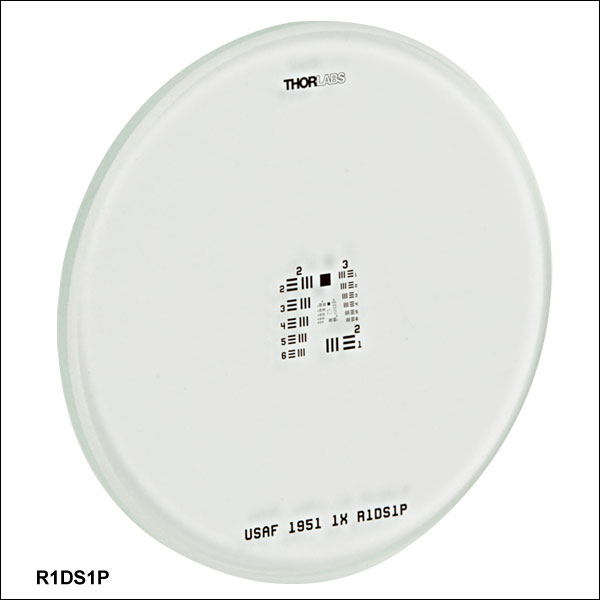
| R1DS1P | 6 | +2 to +7 | Single Set | Ø1" |
| R1DS1N | ||||
| R1DS1P1 | 8 | 0 to +7 | ||
| R1DS1N1 | ||||
| R1DS1P2 | 6 | +2 to +7 | Wheel | |
| R1DS1N2 | ||||
| R1L1S1P | 10 | -2 to +7 | Combination | 18 mm x 18 mm |
| R1L1S1N | ||||
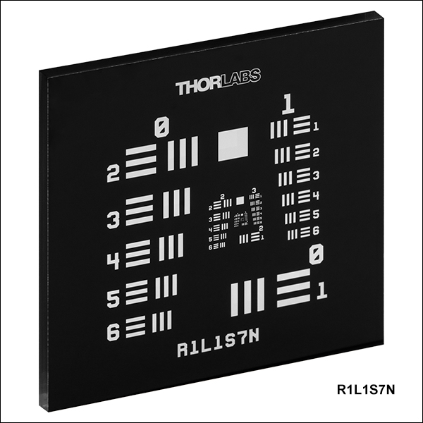
| R1L1S7P | 8 | 0 to +7 | Single Set | 1" x 1" |
| R1L1S7N | ||||
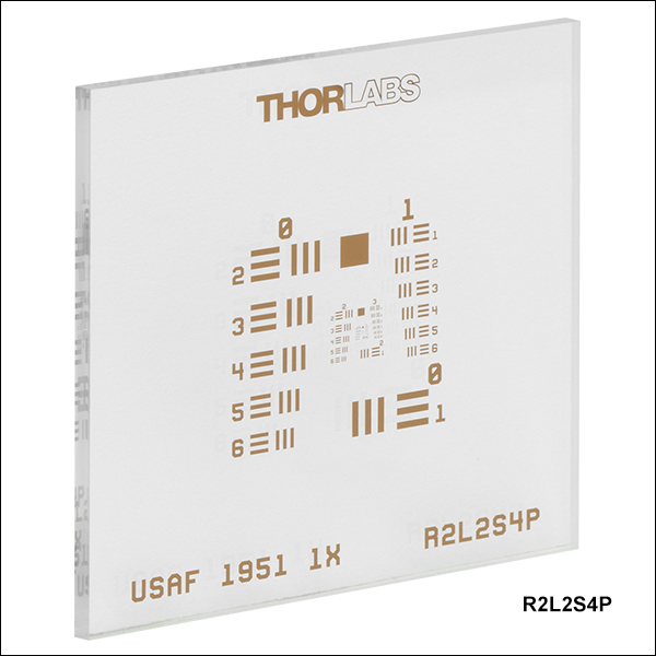
| R2L2S4P | 1.5" x 1.5" | |||
| R2L2S4N | ||||
| R3L1S4P1 | 3" x 1" | |||
| R3L1S4N1 | ||||
| R3L1S4P | 6 | +2 to +7 | Wheel | |
| R3L1S4N | ||||
| R3L1S4PR | ||||
| R3L1S1B | 0 to +5 | Single Set | ||
| R3L3S1P | 10 | -2 to +7 | Single Set | 3" x 3" |
| R3L3S1N | ||||
| R3L3S1PR | ||||
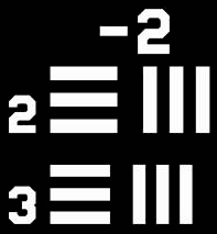
Example Line Sets
These resolution targets have a series of horizontal and vertical lines that are used to determine the resolution of an imaging system. A set of six elements (horizontal and vertical line pairs) are in one group, and ten groups compose the resolution chart. The image below shows Elements 2 and 3 of Group -2 on a resolution target.
With line sets of three, these targets offer the advantage of an increased ability to recognize spurious resolution. Spurious resolution occurs when a set of lines is sufficiently blurred such that the overlap appears to form inverted, more distinct lines. This can cause a misreading of the resolution of the optical system, since it will appear that the lines are distinguishable. Spurious resolution also results in the appearance of one less line than exists in the line set. Since the difference between three lines and two is more easily noticed than the difference between five lines and four, for example, it is easier to recognize the occurrence of spurious resolution in targets with sets of only three lines.
The spacing between the lines in each element is equal to the thickness of the line itself. When the target is imaged, the resolution of an imaging system can be determined by viewing the clarity of the horizontal and vertical lines. The largest set of non-distinguishable horizontal and vertical lines determines the resolving power of the imaging system. The chart below lists the number of line pairs per millimeter for a given element within a group based on the equation below. With our resolution targets, the maximum resolution is 228.0 line pairs per millimeter, which equates to roughly 4.4 µm per line pair. The 3" x 3" targets feature ten groups from -2 to +7; the 3" x 1" targets feature eight groups from 0 to +7; the 3" x 1" wheel pattern versions feature nine targets, each with six groups from +2 to +7; the 3" x 1" birefringent target features six group, from 0 to +5; the 1.5" x 1.5" targets feature eight groups from 0 to +7; the 1" x 1" targets feature eight groups from 0 to +7; the 18 mm x 18 mm (0.71" x 0.71") combined targets feature six groups from +2 to +7; the Ø1" targets feature either six groups, from +2 to +7, or eight groups, from 0 to +7; and the Ø1" wheel pattern versions feature six targets, each with six groups from +2 to +7.
| Element | Group Number | |||||||||
|---|---|---|---|---|---|---|---|---|---|---|
| -2 | -1 | 0 | 1 | 2 | 3 | 4 | 5 | 6 | 7 | |
| 1 | 0.250 | 0.500 | 1.00 | 2.00 | 4.00 | 8.00 | 16.00 | 32.00 | 64.00 | 128.00 |
| 2 | 0.280 | 0.561 | 1.12 | 2.24 | 4.49 | 8.98 | 17.95 | 36.0 | 71.8 | 144.0 |
| 3 | 0.315 | 0.630 | 1.26 | 2.52 | 5.04 | 10.10 | 20.16 | 40.3 | 80.6 | 161.0 |
| 4 | 0.353 | 0.707 | 1.41 | 2.83 | 5.66 | 11.30 | 22.62 | 45.3 | 90.5 | 181.0 |
| 5 | 0.397 | 0.793 | 1.59 | 3.17 | 6.35 | 12.70 | 25.39 | 50.8 | 102.0 | 203.0 |
| 6 | 0.445 | 0.891 | 1.78 | 3.56 | 7.13 | 14.30 | 28.50 | 57.0 | 114.0 | 228.0 |
Click to Enlarge
Close Up of the R3L3S6P NBS 1952 Target
NBS 1952 Targets
- Allows for One-Pass Scanning
- Spurious Resolution Minimized by Line Sets of Three
- Positive Targets Available
- 1" x 3" and 3" x 3" Sizes
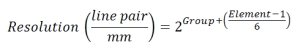
NBS 1952 Targets have sets of three vertical lines and sets of three horizontal lines. Each line and the space between it and the next line can be thought of as a line pair or a cycle. The resolution that each target is able to test is given by the frequency of line pairs in line pairs/mm (lp/mm). A list of every frequency available between our two NBS 1952 targets is given in the table below, along with the corresponding line widths.
These targets offer two main advantages: the minimization of spurious resolution and the feasibility of one-pass scanning. Spurious resolution occurs when a set of lines is sufficiently blurred such that the overlap appears to form inverted, more distinct lines. This can cause a misreading of the resolution of the optical system, since it will appear that the lines are distinguishable. Spurious resolution also results in the appearance of one less line than exists in the line set. Since the difference between three lines and two is more easily noticed than the difference between five lines and four, for example, it is easier to recognize the occurrence of spurious resolution in targets with sets of only three lines.
The advantage of one-pass scanning is made possible by the arrangement of the line sets on these targets. The horizontal and vertical line sets are arranged in an identical fashion, with identical frequencies, such that the target is symmetric across a diagonal line from the upper left to the lower right. If one scans from left to right or from top to bottom on the target, the frequency of the lines will increase until the center is reached and then decrease to the opposite edge. Whether done horizontally or vertically, this single pass across the full pattern covers each frequency available on the target. Thus, movement in only one direction is required to determine the resolution of an optical system.
| Resolution (lp/mm) | Line Width (µm) | Resolution (lp/mm) | Line Width (µm) | Resolution (lp/mm) | Line Width (µm) | Resolution (lp/mm) | Line Width (µm) |
|---|---|---|---|---|---|---|---|
| 0.48 | 1041.7 | 2.24 | 223.2 | 6.8 | 73.5 | 20 | 25 |
| 0.56 | 892.9 | 2.4 | 208.3 | 8 | 62.5 | 24 | 20.8 |
| 0.68 | 735.3 | 2.72 | 183.3 | 9.6 | 52.1 | 28 | 17.9 |
| 0.8 | 625 | 2.8 | 176.8 | 11.2 | 44.6 | 34 | 14.7 |
| 0.96 | 520.8 | 3.2 | 156.3 | 12 | 41.7 | 40 | 12.5 |
| 1.12 | 446.4 | 3.4 | 147.1 | 13.6 | 36.8 | 48 | 10.4 |
| 1.36 | 367.6 | 4 | 125 | 14 | 35.7 | 56 | 8.9 |
| 1.6 | 312.5 | 4.8 | 104.2 | 16 | 31.3 | 68 | 7.4 |
| 1.92 | 260.4 | 5.6 | 89.3 | 17 | 29.4 | 80 | 6.3 |

Click for Details
Microscope Image of R2L2S1N Negative Test Target
NBS 1963A Targets
- Positive, Negative, and Birefringent Targets Available
- High-Frequency Option
- 2" x 2" Size for Dedicated Targets, 1" x 3" Size for Combined Target
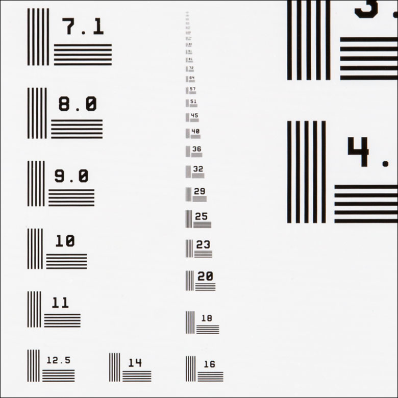
NBS 1963A Targets have line sets of five vertical and five horizontal lines. Each line and the space between it and the next line can be thought of as a line pair or a cycle. The resolution that each target is able to test is given by the frequency of the cycles in cycles/mm. On Thorlabs' NBS 1963A targets, each line set is labeled with its frequency. By determining the smallest lines that are distinguishable (highest cycles/mm), you can determine the resolution of an imaging system.
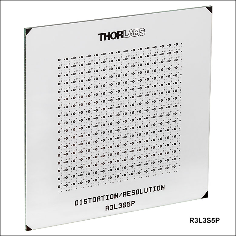
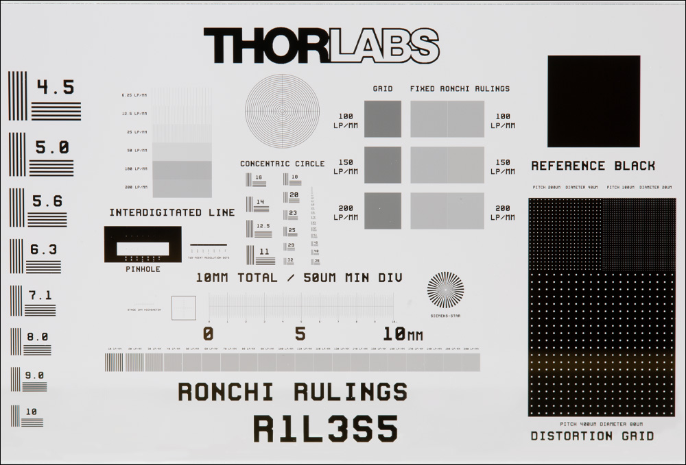
Our standard NBS 1963A targets offer 26 line sets with resolutions scaled from 1.0 cycles/mm to 18.0 cycles/mm. For more rigorous resolution testing, our high-frequency NBS 1963A targets have 48 line sets with frequencies from 1.0 cycles/mm to 228 cycles/mm, and our R1L3S5P combined resolution and distortion test target has 35 line sets with frequencies from 4.5 cycles/mm to 228 cycles/mm. The size of each cycle is simply the reciprocal of the frequency and is given for all available frequencies in the table below. For the individual line width, divide the cycle size in half.
| Cycles/mm | Cycle Size | Cycles/mm | Cycle Size | Cycles/mm | Cycle Size | Cycles/mm | Cycle Size |
|---|---|---|---|---|---|---|---|
| 1.0 | 1.00 mm | 4.0 | 0.250 mm | 16.0 | 0.063 mm | 64.0 | 0.016 mm |
| 1.1 | 0.909 mm | 4.5 | 0.222 mm | 18.0 | 0.056 mm | 72.0 | 0.014 mm |
| 1.25 | 0.800 mm | 5.0 | 0.200 mm | 20.0 | 0.05 mm | 81.0 | 0.012 mm |
| 1.4 | 0.714 mm | 5.6 | 0.179 mm | 23.0 | 0.043 mm | 91.0 | 0.011 mm |
| 1.6 | 0.625 mm | 6.3 | 0.159 mm | 25.0 | 0.040 mm | 102 | 0.010 mm |
| 1.8 | 0.556 mm | 7.1 | 0.141 mm | 29.0 | 0.034 mm | 114 | 0.009 mm |
| 2.0 | 0.500 mm | 8.0 | 0.125 mm | 32.0 | 0.031 mm | 128 | 0.008 mm |
| 2.2 | 0.455 mm | 9.0 | 0.111 mm | 36.0 | 0.028 mm | 144 | 0.007 mm |
| 2.5 | 0.400 mm | 10.0 | 0.100 mm | 40.0 | 0.025 mm | 161 | 0.0062 mm |
| 2.8 | 0.357 mm | 11.0 | 0.091 mm | 45.0 | 0.022 mm | 181 | 0.0055 mm |
| 3.2 | 0.313 mm | 12.5 | 0.080 mm | 51.0 | 0.020 mm | 203 | 0.0049 mm |
| 3.6 | 0.278 mm | 14.0 | 0.071 mm | 57.0 | 0.018 mm | 228 | 0.0044 mm |
Click to Enlarge
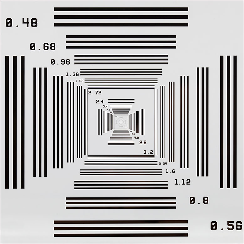
Close Up of the R1L1S3P Sector Star Pattern
Sector Star Targets
Sector star targets, also known as Siemens star targets, consist of a number of dark bars that increase in thickness as they radiate out from a shared center. The blank spaces between the bars can themselves be thought of as light bars, and they are designed to be the same thickness as the dark bars at any given radial distance. Theoretically, the bars meet only at the exact middle point of the target. Some sector star targets, including all those sold on this page, have a blank center circle that cuts the bars off before they touch. However, depending on the resolution of the optical system through which the targets are viewed, the bars will appear to touch at some distance from the center. By measuring this distance, the user is able to define the resolution of the optical system.
To calculate the resolution at any given radial distance from the center of the sector star, start by calculating the thickness of a line pair, or one dark bar and one light bar, at that radius. This can be done using the formula for the chord length, given below, where r is the radial distance from the center. The angle Θ is the number of degrees covered by one pair of light and dark bars and is equal to 360° divided by the total number of bars. Once the thickness of the line pair is calculated, the resolution is the reciprocal of the thickness.
Thorlabs offers two dedicated sector star targets (R1L1S2P and R1L1S3P) and three targets that include sector stars along with other patterns (R1L3S5P, R1L1S1P, and R1L1S1N). The table below summarizes the sector star pattern on each target.
| Item # | Pattern Type | Sector Star Pattern Outer Diameter | Center Circle Diameter | Number of Bars | Resolution at Outer Diameter | Resolution at Center Circle |
|---|---|---|---|---|---|---|
| R1L1S2P | Positive | 10 mm | 200 µm | 36 Over 360° | 1.15 lp/mm | 57.5 lp/mm |
| R1L1S3P | 72 Over 360° | 2.29 lp/mm | 115 lp/mm | |||
| R1L1S2N | Negative | 36 Over 360° | ||||
| R1L1S3N | 72 Over 360° | |||||
| R1L3S5P | Positive | 2 mm | 100 µm | 36 Over 360° | 5.75 lp/mm | 115 lp/mm |
| R1L1S1P | Positive | 2 mm | 20 µm | 36 Over 360° | 5.75 lp/mm | 575 lp/mm |
| R1L1S1N | Negative |

Click to Enlarge
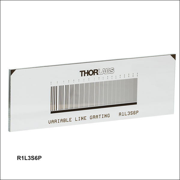
Close Up of R1L3S6P Variable Line Grating Pattern
Variable Line Gratings
Line gratings consist of dark, parallel bars with widths that are equal to the distance between them. In any line grating, one dark bar and one blank space compose a line pair. The resolution of an optical system is dependent on its ability to distinguish adjacent line pairs. Thus, the grating resolution is defined by the number of line pairs in a given amount of space and is typically given in line pairs per millimeter (lp/mm). A variable line grating has some number of grating sections, which increase or decrease in resolution as you move from one to the next. By identifying the highest resolution line grating that an optical system is able to resolve, the user determines the resolution of the system.
Thorlabs offers a variable line grating target with a range of resolutions from 1.25 lp/mm to 250 lp/mm. The table below gives the included resolutions along with a conversion of the line pair size.
| lp/mm | Line Pair Size | lp/mm | Line Pair Size | lp/mm | Line Pair Size |
|---|---|---|---|---|---|
| 1.25 | 0.80 mm | 3.85 | 0.26 mm | 16.67 | 0.06 mm |
| 1.67 | 0.60 mm | 4.17 | 0.24 mm | 50 | 0.02 mm |
| 2.08 | 0.48 mm | 5.0 | 0.20 mm | 100 | 0.01 mm |
| 2.5 | 0.40 mm | 6.67 | 0.15 mm | 200 | 0.005 mm |
| 2.86 | 0.35 mm | 10.0 | 0.10 mm | 250 | 0.004 mm |
| 3.33 | 0.30 mm | 12.5 | 0.08 mm | - | - |
Click to Enlarge
This graph shows the transmission of the soda lime glass used in the positive and negative test targets. It is not representative of the soda lime glass used in the R3L1S1B birefringent 1951 USAF test target.
Click to Enlarge
Spectral Curves of Reflective Test Targets
The large difference between the chrome (blue line) and low-reflectivity coated chrome (red line) in the visible region means that the positive reflective targets have high contrast between the pattern and the background.

Click to Enlarge
This graph shows a sample transmission curve of a R3L1S1B birefringent target, including the slide, cover glass, and birefringent liquid crystal polymer layer.
Click to Enlarge
This graph shows the transmission of a 10 mm thick sample of N-BK7, the material used for the substrate and cover plate of the R2L2S1B birefingent target.

Jason Williamson
Director of Business Development
Thorlabs Spectral Works
Need a Quote?
| Customization Parameters | ||
|---|---|---|
| Substrate Sizea | Min | 8 mm x 8 mm (5/16" x 5/16") |
| Max | 85 mm x 85 mm (3.35" x 3.35") | |
| Substrate Materials | Soda Lime Glass UV Fused Silica Quartz |
|
| Coating Material | Chromeb Low-Reflectivity Chromec |
|
| Coating Optical Density | ≥3d or ≥6e @ 430 nm | |
| Minimum Pinhole/Spot | Ø1 µm | |
| Minimum Line Width | 1 µm | |
| Line Width Tolerance | -0.25 / +0.50 µm | |
| Maximum Line Density | 500 lp/mm | |
Custom OEM Test Targets and Reticles
Our in-house photolithographic design and production capabilities enable us to create a range of patterned optics. We manufacture test targets, distortion grids, and reticles at our Thorlabs Spectral Works facility in Columbia, South Carolina. These components have served a wide variety of applications, being implemented in microscopes, imaging systems, and optical alignment setups.
In addition to our catalog test targets and reticles offered from stock, we can provide custom chrome patterns on soda lime, UV fused silica, or quartz substrates from 8 mm by 8 mm up to 85 mm by 85 mm. Substrates can be cut to shape for your application. Our photolithographic coating process allows us to create chrome features down to 1 µm. A few sample patterns are shown below, which can be made positive or negative, as shown in the image directly below.
For a quote on custom test targets and reticles, please contact us at TSW@thorlabs.com.
Sample Patterns
 Click to Enlarge
 Click to Enlarge
 Click to Enlarge
 Click to Enlarge
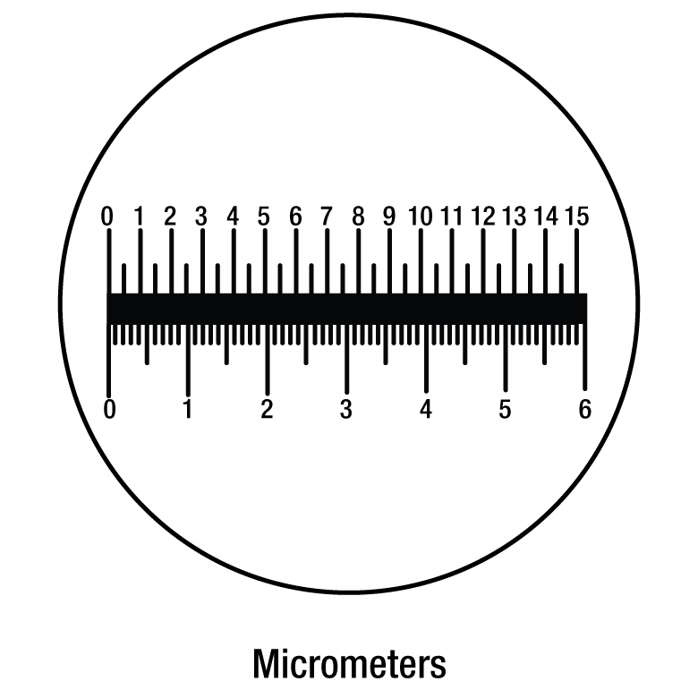 Click to Enlarge
 Click to Enlarge
 Click to Enlarge
 Click to Enlarge
Example Applications
- Etched Reticles
- Gray Scale Masks
- Resolution Reticles
- Diagnostic Reticles
- Recreational Scopes
- Notching Reticles
- Eyepiece Scales
- Illuminated Crosshairs
- Obstruction Targets
- Binocular Reticles
Click to Enlarge
Positive and Negative Crosshair Sample Pattern
This tab details an optimal cleaning technique developed by our engineers for cleaning reticles, test targets, distortion targets, and calibration targets.
Cleaning Procedure
- Use a clean wet sponge, preferably made of polyvinyl alcohol (PVA), and dish detergent to gently scrub the front and back surfaces of your reticle or target.
- Rinse with water.
- Blow dry with clean dry air, or allow the reticle or target to air dry on a clean surface.
We do not suggest using a towel, rag, or wipe to dry the surface. If contamination persists, soak the reticle or target in a detergent and water solution for 1 hour, repeating as necessary.
| Posted Comments: | |
Daniel Penagos
(posted 2024-11-07 01:01:26.553) Hi, Could you guys offer a 1inch 1951 USAF target for reflection too? Currently this only possible in the 3x1 format, not the 1inch one. cdolbashian
(posted 2024-11-12 11:42:02.0) Thank you for reaching out to us with this inquiry. We have both positive and negative test targets in the 1"x1" format as well as the 1" round format. I am not sure exactly what kind of target you are looking for in this sense. I have contacted you directly to discuss your application and requirements. Moshe Peleg
(posted 2024-11-07 17:02:26.517) Hello,
I have this product in the lab. What is its error percentage? cdolbashian
(posted 2024-11-12 09:19:17.0) Thank you for reaching out to us with this inquiry. For the target R1L3S6PR, we have measured an error in center-to-center position of features of +/-100nm, and an error in width/dimension of features on the order of +/-500nm. Gyeonghun Kim
(posted 2024-10-22 15:01:35.263) Hi, I would like to know the thickness of the Liquid Crystal Polymer layer in the birefringent 1951 USAF test target (R3L1S1B). I understand that each resolution target may have different retardance values. I’m just looking for a ballpark figure. Thanks. cdolbashian
(posted 2024-10-28 09:48:21.0) Thank you for contacting Thorlabs. We process the 1951 USAF Birefringent Resolution Test Targets by controlling the retardance rather than the thickness of the Liquid Crystal Polymer layer. The R3L1S1B has a retardance of approximately 0.5 waves at 532nm. Minh-Chau Nguyen
(posted 2024-06-14 09:11:59.607) Hello,
My name is Minh-Chau Nguyen, R&D engineer at Phasics SA, France. I am writing you in order to consult the characteristics of the birefringent test target R3L1S1B.
I carried out a measurement of the retardance on your test target. The measurement is based on the light intensity while rotating a linear retarder under a polarized incident beam. The retardance is then calculated from the min and max of intensity. From the result, I have some conclusions:
- A significant retardance presents on the whole test target (inside and outside the pattern).
- The measured retardance is close to the data announced by Thorlabs. The difference of retardance is relatively small between the pattern and the surrounding zone.
- The difference between the pattern and the surrounding zone is mostly on the angle of fast-axis (Δθ ≈ 33°), which is not mentioned in the description.
Can you please validate my method of measurement as well as the result on the retardance and the angle of fast-axis, since it is not clearly mentioned in the description?
I am looking forward to hearing from you soon. Thank in advance.
Yours sincerely,
Minh-Chau Nguyen cdolbashian
(posted 2024-07-01 04:29:26.0) Thank you for contacting Thorlabs. The retardance of entire test target can be slightly non-uniform, as usually this R3L1S1B is used as a visual resolution tool. The typical fast axis angle of background and pattern is 0 degree and 45 degrees respectively. Again, as a visual tool, the retardance and axis angle are not tightly controlled and may vary from lot to lot. A Babinet Compensator is used for retardance measurement during production process, the intensity measurement approach you mentioned is a common method for retardance testing, it should also be feasible. Yudong Fan
(posted 2024-05-21 21:03:23.003) The .step file and solidwork file are not valid cdolbashian
(posted 2024-05-24 02:45:45.0) Thank you for reaching out to us. I have contacted you directly to inquire regarding the problems you are having with the step files. Michael Tan
(posted 2024-04-16 15:05:28.9) Hi, I would like to check if there is the same negative target but with smaller diameter available for purchase? ksosnowski
(posted 2024-04-22 04:20:33.0) Hello Michael, thanks for reaching out to Thorlabs. We have offered some custom patterns and sizes before. I have reached out directly to discuss your application in further detail. luo kun
(posted 2023-12-04 16:23:03.573) group 2-7中1-6分别对应多少lp/mm cdolbashian
(posted 2023-12-11 10:44:00.0) Thank you for reaching out to us with this inquiry. All information regarding the line spacing and frequency is outlined on the product page above. Additionally, as this is an industry standard test target pattern, 1951 USAF test target, additional information can be found on the web. I have linked you to some of these resources via email. Louise Baehr
(posted 2022-10-26 11:59:29.04) Dear Sir or Madam,
I am sorry to bother you. I would like to have more information on how you calculated the outer and inner frequency of your Siemens star target.
Indeed, when I use your formula, taking 72 bars and so theta = 360°/72 = 5 and the outer diameter of 10mm, I get:
c = 2 * 10mm * sin(5°/2) = 0.8724 mm
resolution = 1 / 0.8724 = 1.1463 lp/mm
BUT, in your table, you indicate a frequency of 2.29 lp/mm at the outer diameter. Could it be possible to have the details of your calculations ? It seems I'm missing something and I really need to understand.
Thank you very much and sorry again for bothering you.
Best regards cdolbashian
(posted 2022-10-31 01:52:36.0) Thank you for reaching out to us! I think perhaps you may be overlooking the negative space between each feature. The size of each line pair should be considered in the 72 segments. Simply take the number of line pairs (72) and divide by the circumference of the circle (2*Pi*5mm~31mm). Taking this quotient (72/31mm) yields ~2.29lp/mm. I have contacted you directly to address this further. Kimi Huang
(posted 2022-02-17 16:32:57.09) Hi Sir,
A question about Reflectivity of pattern and clear area.
Would like to check the Reflectivity % of pattern is ? in the plot, it looks have high R% of pattern? but not make sense to me becuase pattern is black pattern. So I think I misunderstand something here.
So, the question is : what is the Reflectivity of Pattern and clear I should use in the model?
Thanks cdolbashian
(posted 2022-02-18 05:09:16.0) Thank you for reaching out to us Kimi. The substrate of the R1DS1P is soda lime glass, while the pattern is made with anti-reflective chrome. The reflectivity of the chrome and the transmission of the soda lime, can be found on the "Graphs" tab on this page. You can approximate the reflectivity of the soda lime glass as 1-Transmission at a given wavelength, but for a true reflectivity value, one must also consider the absorption of the soda lime substrate. I have reached out to you directly to discuss this further in context of your particular light source. Ulrich Leischner
(posted 2021-11-03 07:47:52.73) I need the precise values of the lines in this target. the value LP/mm is not completely clear. Is this the full diameter of 3 lines, or is this the periodic length (full diameter of 2 lines, a negative and a positive one)
A drawing with the values in the PDF would be very helpful.
Regards jgreschler
(posted 2021-11-12 04:45:20.0) Thank you for reaching out to Thorlabs. The definition of line pairs per millimeter (lp/mm) is defined by a pair of lines, one bright and one dark, in a given spacing. For example, if the specification is 1 lp/mm, that means that the coated line is 0.5mm and the uncoated line is 0.5mm. You can read more about this definition in our Resolution Targets tab at the top of the product page, further literature can be found here https://en.wikipedia.org/wiki/1951_USAF_resolution_test_chart Fidel Vega
(posted 2021-10-11 04:24:48.963) Dear Sir or Madam,
We are interested in buying some customized reticles & calibration tests. I would need to contact your technical department to ask some questions about the features of the items that we need. The 1st October I sent a message to TSW@thorlabs.com with this request, but I have not yet received any feedback from your side.
Thank you
Fidel cdolbashian
(posted 2021-12-23 11:38:58.0) Thank you for contacting us here at Thorlabs! We apologize deeply for our lack of communication. We have reached out to you directly to discuss your custom. Andrew Keys
(posted 2021-08-19 12:14:32.71) I recently ordered a positive and negative version of the R1L1S1P Resolution and Distortion Target. To be able to precisely navigate around the elements on this target, I ordered a XYF1 mount. Upon receipt, I now realize that the 18mm x 18mm target cannot easily be mounted in the XYF1 without covering much of the target elements. What is the recommended method of mounting these R1L1S1P targets? cdolbashian
(posted 2021-08-27 09:29:10.0) Thank you for reaching out to us here at Thorlabs! The test target you have selected is intended for use with a standard microscopy system, rather than free space optics. Because this is the case, using it with the XYF1 may result in the obscuration of some of the edges of the test pattern, due to the size of the target. I have reached out to you directly with alternative solutions. We are always hungry for feedback, so we appreciate you bringing this incompatibility of seemingly-compatible parts to our attention. moti yanuka
(posted 2021-02-17 20:19:35.317) I am interested in resolution and distortion targets, could you send to me quotations? YLohia
(posted 2021-02-17 10:20:33.0) Hello, thank you for your interest in our products. Quotes can be requested by contacting our Sales Team (sales@thorlabs.com) or by adding the items to your cart and clicking "Request a Quote" button on your cart page. Ananth Rao
(posted 2020-09-15 06:34:45.553) Hi ,
We have bought this resolution target R1L1S1N, there are two peculiar questions,
1. What is methodology to clean the target? Is there any documentation?
2. What is the surface flatness of the target? YLohia
(posted 2020-09-16 10:32:26.0) Hello, thank you for contacting Thorlabs. Unfortunately, we don't have specific documentation on cleaning the R1L1S1N. That being said, we do have a general optics cleaning guide here: https://www.thorlabs.com/newgrouppage9.cfm?objectgroup_id=9025. I have reached out to you directly to discuss your request. wen cao
(posted 2020-06-24 09:12:46.36) 这个分辨率板是透明的吗?可以背光照射吗? YLohia
(posted 2020-06-24 09:15:24.0) Thank you for contacting Thorlabs. An applications engineer from our team in China (techsupport-cn@thorlabs.com) will reach out to you directly. 程访 许
(posted 2019-11-26 16:41:58.167) 此产品镀的铬膜,对633nm的光,反射率是多少?望回复,我在产品介绍中没看到,最近课题组购买了此产品,我需要这个参数。 nbayconich
(posted 2019-12-03 04:04:53.0) Thank you for contacting Thorlabs. Although we do not specify a guaranteed reflectivity of this chrome coating, the reflectivity will be about 25% at 633nm. I will reach out to you directly. Soocheol Kim
(posted 2019-11-19 21:33:39.29) Dear Sir/Madame,
I checked the retardation of the entire target, which was to be 280±20 nm.
Is this retardation a retardation between the entire target and the patterned area?
I'd like to know the retardation between the entire target and the patterned area. nbayconich
(posted 2019-11-25 10:35:23.0) Thank you for contacting Thorlabs. The R2L2S1B is a half wave plate for 546 nm (or 273nm @546nm). The entire target has the same retardance, the pattern is created by having a 45 deg azimuth difference against the background. Anne De Paepe
(posted 2019-11-06 10:27:10.69) Dear Sir/Madam,
I am looking for a spatial resolution test for my Raman microscope (532nm, 633nm and 785nm lasers). Where I worked before we had a USAF target of Si on Quartz but not sure if this is the best one. What would you recommend?
Thank you YLohia
(posted 2019-11-08 10:51:17.0) Hello, thank you for contacting Thorlabs. Our Chrome on Glass targets are suitable for all wavelengths mentioned by you. Ultimately, the use comes down to personal preference, availability, and possible requirements on transmission/reflectivity. I have reached out to you directly to gain a better sense of your needs. Soojung Kim
(posted 2019-11-05 08:24:52.273) Hello.
How thick is the patterned chrome on R1L1S1P test target? It's very important point to test axial resolution of our equipment.
Sincerely. YLohia
(posted 2019-11-05 10:46:52.0) The thickness of the chrome layer on our targets is 0.120 µm. More information can be found in the specs table in the Overview tab. Fernando Brandi
(posted 2019-08-13 08:52:46.3) Dear Sir/Madame,
I am interested in you R2L2S1B Birefringent NBS 1963A Resolution Target, 2" x 2" for testing a polarizing imaging system.
For our porpoises we need to use both fundamental 1064 nm and second harmonic 532 nm laser light.
In order to evaluate the use of the R2L2S1B Birefringent NBS 1963A Resolution Target for our application I need to know the total optical path length of the target at the two wavelength (1064 nm and 532 nm) and for both ordinary and extraordinary polarization orientation.
Looking forwrd for your reply I thank you for the attention.
Kind regards,
Fernando Brandi, PhD
Consiglio Nazionale delle Ricerche (CNR)
Istituto Nazionale di Ottica (INO)
Sede Secondaria "A. Gozzini" di Pisa
Via Moruzzi 1, 56124-Pisa, Italy
Tel. +39 050 315 2584
Fax. +39 050 315 2247
E-Mail: fernando.brandi@ino.cnr.it
http://research.ino.it/Groups/ilil/it/about_it/ YLohia
(posted 2019-08-28 03:45:30.0) Hello Fernando, thank you for contacting Thorlabs. The design wavelength for half-wave retardance for the R2L2S1B is 546nm. The liquid crystal delta(n) is 0.1555 at 550 nm. Unfortunately, we do not have the data for your exact operating wavelengths. We reached out to you directly to discuss this further. user
(posted 2019-07-01 11:43:13.403) What mechanical mount do you suggest to hold R1L1S1P or R1L1S1N? YLohia
(posted 2019-07-01 12:19:11.0) Hello, thank you for contacting Thorlabs. We recommend the XF50, PC2, FH2, SFH2, CH1A, or FP01 mounts for these targets. Robert Standaert
(posted 2019-05-13 16:45:12.813) High-resolution or vector images of the targets would be very helpful. YLohia
(posted 2019-05-14 10:10:55.0) Hello, thank you for your feedback! We are in the process of discussing the possibility of publishing this information on our website. sureshbil67
(posted 2018-08-11 07:29:46.71) I want to know resolution target patterns specification of Night vision devices YLohia
(posted 2018-09-17 09:59:01.0) Hello, thank you for contacting Thorlabs. I have reached out to you directly to discuss your application in more detail. haolin.zhang
(posted 2018-05-09 20:12:29.3) I am using the R2L2S1B Resolution Target to implement a holographic experiment. Could you please provide me the refractive index of the liquid crystal polymer layer aligned in the target, please? Also, could you please provide the information about the material of this liquid crystal polymer layer? Thanks in advance. YLohia
(posted 2018-05-11 08:39:33.0) Hello, thank you for contacting Thorlabs. Unfortunately, we cannot disclose this information since it is proprietary. ayoub.mghari
(posted 2017-11-29 11:27:24.9) I am interested in ordering this target but I have the following question:
My understanding is that the target is made out of Chrome coating on Soda Lime Glass. This, due to a given illumination system will result in shadows on the rear side, correct?
Is it possible to have this target on a non-transparent glass?
Please send me a Quote by E-mail. nbayconich
(posted 2017-12-27 04:07:26.0) Thank you for contacting Thorlabs. You are correct if using the positive resolution targets then light incident on the front of the target light will reflect off of the chrome patterns. The negative targets have clear patterns with chrome coating the rest of the substrate which makes these intended for back lit applications. We can provide custom targets with non-transparent substrate such as opal. I will reach out to you directly to discuss our custom target capabilities. miguel.pleitez
(posted 2017-05-24 13:59:18.767) would it be possible to get this test targets but on a ZnSe substrate instead of glass? I would be very interested on them. Let me know.
Thanks in advance. nbayconich
(posted 2017-06-13 09:48:26.0) Thank you for contacting Thorlabs. I will contact you directly about our custom capabilities. yoonys
(posted 2016-12-06 01:07:03.37) It'd be helpful to draw what "line pair" is on the website, like Figure 1(b) in the following link.
http://www.edmundoptics.com/resources/application-notes/imaging/resolution/ tcampbell
(posted 2016-12-15 11:47:36.0) Response from Tim at Thorlabs: Thank you for your feedback. We will look into adding a diagram explaining line pairs and camera resolution soon. theodore_morse
(posted 2016-11-16 11:49:07.157) I wish to use a blue laser (266 nm) to get the
resolution. In the masks that you use, will it transmit blue light?
I would prefer it to be a quartz substrate.
Ted Morse
Prof. (Research)
School of Engineering
Brown University
Providence, RI 02912 tfrisch
(posted 2016-11-18 10:32:42.0) Hello Ted, thank you for contacting Thorlabs. I am checking on the transmission and reflection of the chrome and soda lime in UV regions now. I will contact you directly when I have more information. user
(posted 2014-06-02 12:59:19.84) What is the line width of the grids on the R1L1S1P resolution target? jlow
(posted 2014-06-03 10:41:23.0) Response from Jeremy at Thorlabs: The grid line width is 5µm for both the 100µm and 50µm grids, and 1.5µm for the 10µm grid. pnon
(posted 2012-12-24 11:58:00.0) Response from Pauline at Thorlabs: The masks used for our test targets are calibrated to NIST-traceable standards. We use contact photolithography with a mask aligner to define the pattern on the glass substrate. Once the pattern is defined, we chemically etch the substrates to produce the finished targets. Although similar in performance with the mask, we do not provide NIST traceable certificates. I will contact you shortly to provide information in getting targets with NIST certificates. mmarcoux
(posted 2012-12-17 10:05:40.897) Are the R1L3S3P distortion targets N.I.S.T. certified/traceable? tcohen
(posted 2012-06-18 10:51:00.0) Response from Tim at Thorlabs: Information on this question was provided for a previous request @400nm below: “The reflectivity of dark pattern on reticle is less than 12% @400nm. For the white pattern, it is just sodium lime glass, so the reflectivity is estimated to be ~ 3.5% @ 400nm ( assuming refractive index is ~ 1.463).” I have contacted you to find out your wavelength and to see if you require more information. cooljkpark
(posted 2012-06-15 07:09:36.0) Can you tell me the reflection coefficient of glass and chrome in your resolution target? bdada
(posted 2012-06-05 19:09:00.0) Response from Buki at Thorlabs to marctessier:
Thank you for participating in our feedback forum. We are developing some new crossed reticles and we have contacted you for a drawing of the custom reticle you need.
We have an office in France and the information is included on the web page linked below that lists our offices and distributors world wide:
http://www.thorlabs.de/Distributors.cfm marctessier
(posted 2012-06-05 17:31:41.0) Hello,
I'm working in Rillieux la Pape, near Lyon, in France, and I must find a custom 1" crossed reticle. I've a PDF file showing it.
I need only one part.
Are you able to supply such good?
Do you have a french retailer?
Best regards,
Marc bdada
(posted 2012-02-27 17:34:00.0) Response from Buki to dick.verhaart:
For our reticle products, we use chrome with O.D.=>3.0 @430nm. The reflectivity of dark pattern on reticle is less than 12% @400nm. For the white pattern, it is just sodium lime glass, so the reflectivity is estimated to be ~ 3.5% @ 400nm ( assuming refractive index is ~ 1.463).
Please contact TechSupport@thorlabs.com if you have any questions. bdada
(posted 2012-02-24 18:46:00.0) Response from Buki at Thorlabs to dick.verhaart:
Thank you for your feedback. We are looking into this and will contact you shortly with more information and post an update here. dick.verhaart
(posted 2012-02-02 05:48:19.0) Can this product (R3L3S1P/N) be used with 405 nm reflective illumination? I find with similar products from other suppliers that the reflection contrast, at this wavelength, between glass and chrome is very small, contrast reversal may occur. Does Thorlabs specific refelctivity of "black"and "white"at 405 nm? bdada
(posted 2011-08-01 14:14:00.0) Response from Buki at Thorlabs:
We measured the smallest grid pattern (10um) of R1L2S2P using a micrometric system, OLYMPUS MX50, and the tolerance of the pattern is < +/-0.1um. Please contact TechSupport@thorlabs.com with additional questions. ajh
(posted 2011-07-26 03:05:25.0) Can you provide specifications for the accuracy of the graduations on your stage micrometers, R1L2S2P and R1L2S1P? I assume they are very accurate but when calibrating image scale you do want to know how accurate your calibrator is. user
(posted 2011-01-31 10:50:15.0) Response from Buki to Paul. Thank you so much for your feedback. We are expanding our selection of reticles and will make them more compatible with our cage system. We will contact you directly to learn how we can better meet your needs. paul
(posted 2011-01-24 12:02:31.0) I am surprised (given the sophistication of your product line)you do not stock reticles that can be used with the cage plate systems. I currently buy reticles elsewhere and then mount them in cage plates. |

 Zoom
Zoom
Click to Enlarge
Microscope Image of R1DS1N Negative Test Target
| Optical Specifications | ||||||
|---|---|---|---|---|---|---|
| Item # | R1DS1P1 | R1DS1N1 | R1DS1P | R1DS1N | R1DS1P2 | R1DS1N2 |
| Pattern | LRa Chrome | Clear | LRa Chrome | Clear | LRa Chrome | Clear |
| Background | Clear | LRa Chrome | Clear | LRa Chrome | Clear | LRa Chrome |
| Surface Flatness | <50 µm | <15 µm | ||||
| Chrome Optical Densityb | ≥3.0 | |||||
- Ø1.00" (Ø25.4 mm) Targets for Alignment in Ø1" Lens Tubes
- Determine Resolution of an Optical System
- Conforms to MIL-S-150A Standard
- Positive and Negative Targets Available
- Sets of Three Lines Minimize Spurious Resolution
Thorlabs offers positive and negative Ø1.00" (Ø25.4 mm) resolution test targets that are made by plating low-reflectivity, vacuum sputtered chrome on a soda lime glass substrate. These targets are available with either 6 groups (+2 to +7) or 8 groups (0 to +7), each with 6 elements, offering a maximum resolution of 228.0 line pairs (one light line and one dark line) per millimeter. We also offer wheel pattern targets that have nine 1951 USAF targets, each with 6 groups (+2 to +7). For more information on the 1951 USAF pattern and available configurations, please see the Resolution Targets tab above.
Because these targets feature sets of three lines, they reduce the occurrence of spurious resolution and thus help prevent inaccurate resolution measurements. For more information on spurious resolution, please see the Resolution Targets tab.
The positive targets with Item # suffixes P, P1, and P2 consist of low-reflectivity chrome patterns plated onto a clear substrate and are useful for front-lit and general applications. Alternatively, the negative targets with Item # suffixes N, N1, and N2 use the same low-reflectivity chrome coating to cover the substrate, leaving the pattern itself clear, and work well in back-lit and highly illuminated applications.

 Zoom
Zoom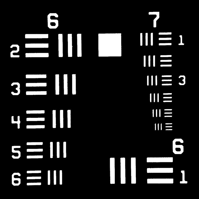
Click to Enlarge
Microscope Image of the smallest groups (6 and 7) on an R1L1S7N Negative Test Target
| Optical Specifications | ||
|---|---|---|
| Item # | R1L1S7P | R1L1S7N |
| Pattern | LRa Chrome | Clear |
| Background | Clear | LRa Chrome |
| Surface Flatness | ≤15 µm | |
| Chrome Optical Densityb | ≥3.0 | |
- 1.00" x 1.00" (25.4 mm x 25.4 mm) Targets for Measuring Resolution Across Image
- Determine Resolution of an Optical System
- Conforms to MIL-S-150A Standard
- Positive and Negative Targets Available
- Sets of Three Lines Minimize Spurious Resolution
Thorlabs offers positive and negative 1.00" x 1.00" (25.4 mm x 25.4 mm) resolution test targets that are made by plating low-reflectivity, vacuum sputtered chrome on a soda lime glass substrate. These targets have 8 groups (0 to +7) with 6 elements, offering a maximum resolution of 228.0 line pairs (one light line and one dark line) per millimeter. For more information on the 1951 USAF pattern, please see the Resolution Targets tab above.
Because these targets feature sets of three lines, they reduce the occurrence of spurious resolution and thus help prevent inaccurate resolution measurements. For more information on spurious resolution, please see the Resolution Targets tab.
The R1L1S7P positive target consists of a low-reflectivity chrome pattern plated on to a clear substrate and is useful for front-lit and general applications. Alternatively, the R1L1S7N negative target uses the same low-reflectivity chrome coating to cover the substrate, leaving the pattern itself clear, and works well in back-lit and highly illuminated applications.

 Zoom
ZoomClick to Enlarge
Microscope Image of the smallest groups (6 and 7) on an R2L2S4N Negative Test Target
| Optical Specifications | ||
|---|---|---|
| Item # | R2L2S4P | R2L2S4N |
| Pattern | LRa Chrome | Clear |
| Background | Clear | LRa Chrome |
| Surface Flatness | ≤15 µm | |
| Chrome Optical Densityb | ≥3.0 | |
- 1.50" x 1.50" (38.1 mm x 38.1 mm) Targets for Measuring Resolution Across Image
- Determine Resolution of an Optical System
- Conforms to MIL-S-150A Standard
- Positive and Negative Targets Available
- Sets of Three Lines Minimize Spurious Resolution
Thorlabs offers positive and negative 1.50" x 1.50" (38.1 mm x 38.1 mm) resolution test targets that are made by plating low-reflectivity, vacuum sputtered chrome on a soda lime glass substrate. These targets have 8 groups (0 to +7) with 6 elements, offering a maximum resolution of 228.0 line pairs (one light line and one dark line) per millimeter. For more information on the 1951 USAF pattern, please see the Resolution Targets tab above.
Because these targets feature sets of three lines, they reduce the occurrence of spurious resolution and thus help prevent inaccurate resolution measurements. For more information on spurious resolution, please see the Resolution Targets tab.
The R2L2S4P positive target consists of a low-reflectivity chrome pattern plated on to a clear substrate and is useful for front-lit and general applications. Alternatively, the R2L2S4N negative target uses the same low-reflectivity chrome coating to cover the substrate, leaving the pattern itself clear, and works well in back-lit and highly illuminated applications.

 Zoom
ZoomClick to Enlarge
Microscope Image of the smallest groups (6 and 7) on an R3L1S4N Negative Test Target
- 3.00" x 1.00" (76.2 mm x 25.4 mm) Targets for Measuring Resolution Across Image
- Determine the Resolution of an Optical System
- Conforms to MIL-S-150A Standard
- Positive, Negative, and Positive Reflective Targets Available
- Compatible with our MLS203 Microscope Stages via MLS203P2 Slide Holder
Thorlabs offers positive and negative 3.00" x 1.00" (76.2 mm x 25.4 mm) resolution test targets that are made by plating vacuum-sputtered low-reflectivity chrome on a soda lime glass substrate. The single targets (Item #s R3L1S4P1 and R3L1S4N1) each have 8 groups (0 to +7) with 6 elements. The wheel pattern targets (Item #s R3L1S4P, R3L1S4N, and R3L1S4PR) have nine 1951 USAF targets, each with 6 groups (+2 to +7). Both sets have a maximum resolution of 228.0 line pairs (one light line and one dark line) per millimeter. For more information on the 1951 USAF pattern, please see the Resolution Targets tab above.
| Optical Specifications | |||||
|---|---|---|---|---|---|
| Item # | R3L1S4P1 | R3L1S4N1 | R3L1S4P | R3L1S4N | R3L1S4PR |
| Pattern | LRa Chrome | Clear | LRa Chrome | Clear | LRa Chrome |
| Background | Clear | LRa Chrome | Clear | LRa Chrome | Chrome |
| Surface Flatness | ≤15 µm | ||||
| Chrome Optical Densityb | ≥3.0 | - | |||
| Chrome Reflectanceb | - | LRa Chrome: <10% Chrome: >40% |
|||
Because these targets feature sets of three lines, they reduce the occurrence of spurious resolution and thus help prevent inaccurate resolution measurements. For more information on spurious resolution, please see the Resolution Targets tab.
Thorlabs' R3L1S4P1 and R3L1S4P positive targets are composed of a low-reflectivity chrome pattern etched on clear soda lime glass, useful for front-lit and general applications. Alternatively, the R3L1S4N1 and R3L1S4N negative targets use low-reflectivity chrome to cover the substrate, leaving the pattern itself clear, and work well in back-lit and highly illuminated applications. The R3L1S4PR positive reflective target is composed of a dark low-reflectivity chrome pattern on a chrome background; the high contrast between the pattern and the background makes this target ideal for reflective applications. See the Graphs tab for details.

 Zoom
Zoom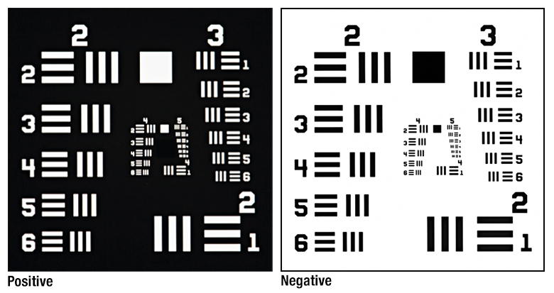
Click to Enlarge
This image depicts groups 2 to 5 of the R3L1S1B target as seen through two crossed polarizers. The positive and negative patterns were produced by rotating the crossed polarizers relative to the target.
| Optical Specifications | |
|---|---|
| Design | Liquid Crystal Polymer Between Soda Lime Glass Slide and Schott D 263® M Cover Glass |
| Slide Thickness | 1.0 mm (0.04") |
| Cover Slip Thickness | 0.2 mm |
- Determine Resolution of a Polarizing Optical System
- Birefringent Target Displays Both Positive and Negative Patterns
- Conforms to MIL-S-150A Standard
- 1.00" × 3.00" (25.4 mm × 76.2 mm) Soda Lime Glass Substrate with Cover Slip
Thorlabs offers a birefringent 1.00" x 3.00" (25.4 mm x 76.2 mm) 1951 USAF resolution test target that is made by sandwiching a birefringent pattern between a soda lime glass slide and a Schott D 263®† M cover slip. The R3L1S1B target features six groups (0 to 5) with six elements per group, offering a maximum resolution of 57.0 line pairs (one light line and one dark line) per millimeter. The test pattern is only observable if the target is placed between a pair of crossed polarizers, as shown in the image to the right. See the Resolution Targets tab above for more details on the test pattern.
The target is designed so that it can display both positive and negative patterns by adjusting the orientation of the test target relative to the crossed polarizers. If the polarizers are aligned with the sides of the slide, the positive image will be formed. If the polarizers are aligned at ~45° to the sides of the slide, the negative image will be formed.
Because of its polarization sensitivity, this resolution target is ideal for calibrating and testing the resolution of our birefringence imaging system and microscopes, polarizing microscopes, microscopes with a Nomarski mode, polarization imaging systems, or Mueller Matrix polarimeters.
† D 263® is a registered trademark of Schott AG.

 Zoom
ZoomClick to Enlarge
Microscope Image of R3L3S1N Negative Test Target
| Optical Specifications | |||
|---|---|---|---|
| Item # | R3L3S1P | R3L3S1N | R3L3S1PR |
| Pattern | LRa Chrome | Clear | LRa Chrome |
| Background | Clear | LRa Chrome | Chrome |
| Surface Flatness | ≤15 µm | ≤15 µm | |
| Chrome Optical Densityb | ≥3.0 | - | |
| Chrome Reflectanceb | - | LRa Chrome: <10% Chrome: >40% |
|
- 3.00" x 3.00" (76.2 mm x 76.2 mm) Targets Offer Resolution up to 4.4 µm per Line Pair
- Determine Resolution of an Optical System
- Conforms to MIL-S-150A Standard
- Positive, Negative, and Positive Reflective Targets Available
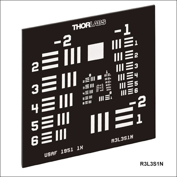
Thorlabs offers positive and negative 3.00" x 3.00" (76.2 mm x 76.2 mm) resolution test targets that are made by plating low-reflectivity chrome on a soda lime glass substrate. These targets have 10 groups (-2 to +7) with 6 elements per group, offering a maximum resolution of 228.0 line pairs (one light line and one dark line) per millimeter. For more information on the 1951 USAF pattern, please see the Resolution Targets tab above.
Because these targets feature sets of three lines, they reduce the occurrence of spurious resolution and thus help prevent inaccurate resolution measurements. For more information on spurious resolution, please see the Resolution Targets tab.
Thorlabs offers the R3L3S1P positive target composed of a low-reflectivity chrome pattern etched on soda lime glass, useful for front-lit and general applications, with a clear soda lime substrate background for front-lit and general applications. Alternatively, the R3L3S1N negative target uses low-reflectivity chrome to cover the substrate, leaving the pattern itself clear, and works well in back-lit and highly illuminated applications. The R3L3S1PR positive reflective target is composed of a dark low-reflectivity chrome pattern on a chrome background; the high contrast between the pattern and the background makes this target ideal for reflective applications. See the Graphs tab for details.

 Zoom
Zoom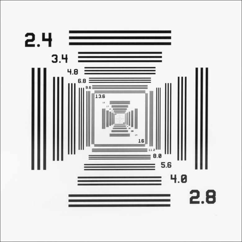
Click to Enlarge
Close Up of the R1L3S10P NBS 1952 Target
| Optical Specifications | |
|---|---|
| Pattern | LRa Chrome |
| Background | Clear |
| Surface Flatness | ≤15 µm |
| Chrome Optical Densityb | ≥3.0 |
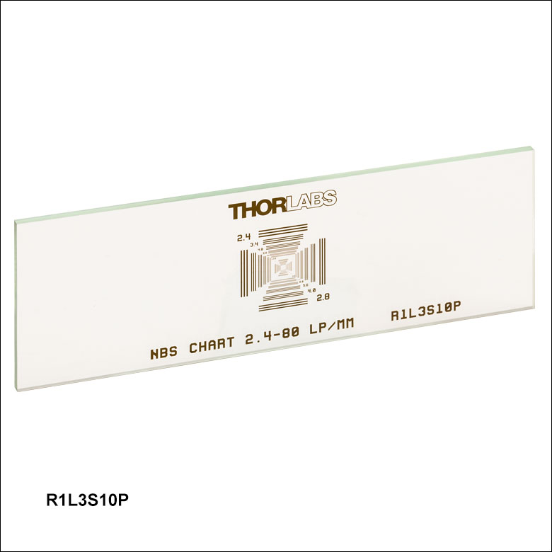
- 3.00" x 1.00" (76.2 mm x 25.4 mm) Target for Measuring Resolution with One-Pass Scanning
- NBS 1952 Target with Centered Crosshair
- Resolutions from 2.4 to 80 lp/mm
- Sets of Three Lines Minimize Spurious Resolution
Thorlabs' 3.00" x 1.00" (76.2 mm x 25.4 mm) NBS 1952 Resolution Target offers 48 sets of lines with 24 different frequencies ranging from 2.4 to 80 line pairs (one light line and one dark line) per millimeter (lp/mm), as listed in the table below. In the center of the NBS 1952 target is a crosshair with a length and width of 610 µm and two concentric circles with diameters of 250 µm and 500 µm. Because the line sets on this target are arranged such that every resolution can be viewed by traveling in only one direction (either horizontally or vertically) along the pattern, the resolution of an optical system can be determined with one pass. For more information about the NBS 1952 pattern, please see the Resolution Targets tab above.
Because this target features sets of three lines, it reduces the occurrence of spurious resolution and thus helps prevent inaccurate resolution measurements. For more information on spurious resolution, please see the Resolution Targets tab.
The pattern on this target is made from plating low-reflectivity, vacuum-sputtered chrome on a 0.06" (1.5 mm) thick soda lime glass substrate to achieve an optical density of ≥3.0 at 430 nm. The dark pattern and clear substrate are useful for front-lit and general applications.
| NBS 1952 Pattern Resolutions | ||||||||||||||||||||||||
|---|---|---|---|---|---|---|---|---|---|---|---|---|---|---|---|---|---|---|---|---|---|---|---|---|
| Resolution (lp/mm) | 2.4 | 2.8 | 3.4 | 4.0 | 4.8 | 5.6 | 6.8 | 8.0 | 9.6 | 11.2 | 12 | 13.6 | 14 | 16 | 17 | 20 | 24 | 28 | 34 | 40 | 48 | 56 | 68 | 80 |
| Line Width (µm) | 208.3 | 176.8 | 147.1 | 125.0 | 104.2 | 89.3 | 73.5 | 62.5 | 52.1 | 44.6 | 41.7 | 36.8 | 35.7 | 31.3 | 29.4 | 25.0 | 20.8 | 17.9 | 14.7 | 12.5 | 10.4 | 8.9 | 7.4 | 6.3 |

 Zoom
ZoomClick to Enlarge
Close Up of the R3L3S6P NBS 1952 Target
| Optical Specifications | |
|---|---|
| Pattern | LRa Chrome |
| Background | Clear |
| Surface Flatness | ≤15 µm |
| Chrome Optical Densityb | ≥3.0 |
- 3.00" x 3.00" (76.2 mm x 76.2 mm) Target for Measuring Resolution with One-Pass Scanning
- NBS 1952 Target with Centered Crosshair
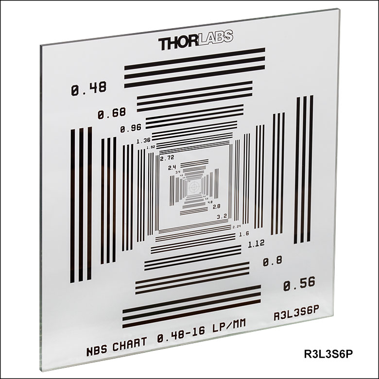
- Resolutions from 0.48 to 16 lp/mm
- Sets of Three Lines Minimize Spurious Resolution
Thorlabs' 3.00" x 3.00" (76.2 mm x 76.2 mm) NBS 1952 Resolution Target offers 48 sets of lines with 24 different frequencies ranging from 0.48 to 16 line pairs (one light line and one dark line) per millimeter (lp/mm), as listed in the table below. In the center of the NBS 1952 target is a crosshair with a length and width of 3100 µm and two concentric circles with diameters of 1250 µm and 2500 µm. Because the line sets on this target are arranged such that every resolution can be viewed by traveling in only one direction (either horizontally or vertically) along the pattern, the resolution of an optical system can be determined with one pass. For more information about the NBS 1952 pattern, please see the Resolution Targets tab above.
Because this target features sets of three lines, it reduces the occurrence of spurious resolution and thus helps prevent inaccurate resolution measurements. For more information on spurious resolution, please see the Resolution Targets tab.
The pattern on this target is made from plating low-reflectivity, vacuum-sputtered chrome on a 0.06" (1.5 mm) thick soda lime glass substrate to achieve an optical density of ≥3.0 at 430 nm. The dark pattern and clear substrate are useful for front-lit and general applications.
| NBS 1952 Pattern Resolutions | ||||||||||||||||||||||||
|---|---|---|---|---|---|---|---|---|---|---|---|---|---|---|---|---|---|---|---|---|---|---|---|---|
| Resolution (lp/mm) | 0.48 | 0.56 | 0.68 | 0.8 | 0.96 | 1.12 | 1.36 | 1.6 | 1.92 | 2.24 | 2.4 | 2.72 | 2.8 | 3.2 | 3.4 | 4.0 | 4.8 | 5.6 | 6.8 | 8.0 | 9.6 | 11.2 | 13.6 | 16 |
| Line Width (µm) | 1041.7 | 892.9 | 735.3 | 625 | 520.8 | 446.4 | 367.6 | 312.5 | 260.4 | 223.2 | 208.3 | 183.8 | 176.8 | 156.3 | 147.1 | 125.0 | 104.2 | 89.3 | 73.5 | 62.5 | 52.1 | 44.6 | 36.8 | 31.3 |

 Zoom
ZoomClick for Details
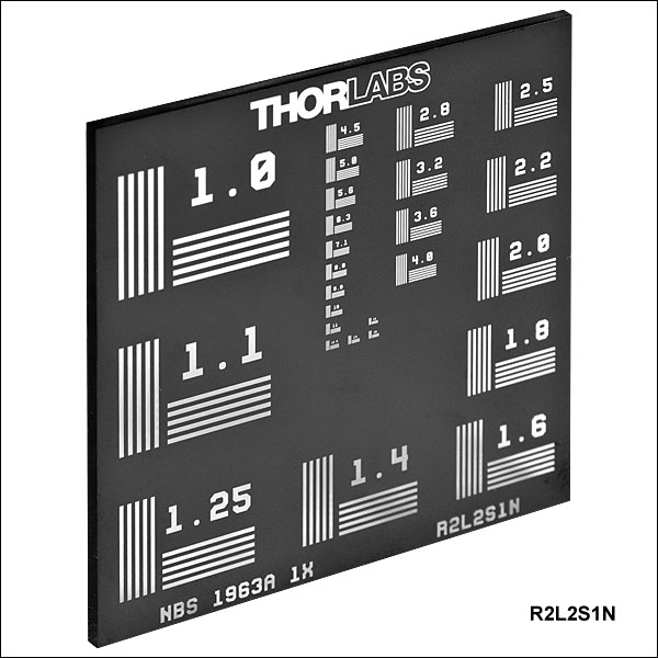
Microscope Image of R2L2S1N Negative Test Target
|
|
| Optical Specifications | ||
|---|---|---|
| Item # | R2L2S1P | R2L2S1N |
| Pattern | LRa Chrome | Clear |
| Background | Clear | LRa Chrome |
| Surface Flatness | ≤15 µm | |
| Chrome Optical Densityb | ≥3.0 | |
- Frequencies from 1 to 18 cycles/mm (See List to the Right)
- Determine Resolution of an Optical System
- 2.00" x 2.00" (50.8 mm x 50.8 mm) Soda Lime Glass Substrate
- Positive and Negative Targets Available
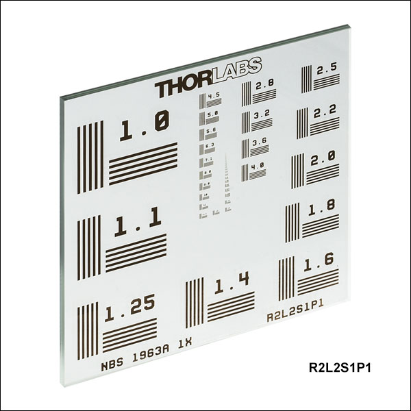
Thorlabs' 2.00" x 2.00" (50.8 mm x 50.8 mm) NBS 1963A resolution test targets offer 26 line sets with frequencies from 1 to 18 cycles/mm, corresponding to cycle sizes from 1.0 mm to 55.6 µm (see the table to the right and the Resolution Targets tab for more information). Each set of lines on the pattern contains five horizontal and five vertical lines and is labeled with the frequency of the lines in cycles/mm, as shown in the images to the right. The resolution of an optical system can be determined by identifying the highest frequency line set that the system is able to resolve.
These resolution targets are offered in positive and negative versions. The R2L2S1P positive target consists of a low-reflectivity chrome pattern plated on to a clear substrate and is useful for front-lit and general applications. Alternatively, the R2L2S1N negative target uses the same low-reflectivity chrome to cover the substrate, leaving the pattern itself clear, and works well in back-lit and highly illuminated applications.

 Zoom
Zoom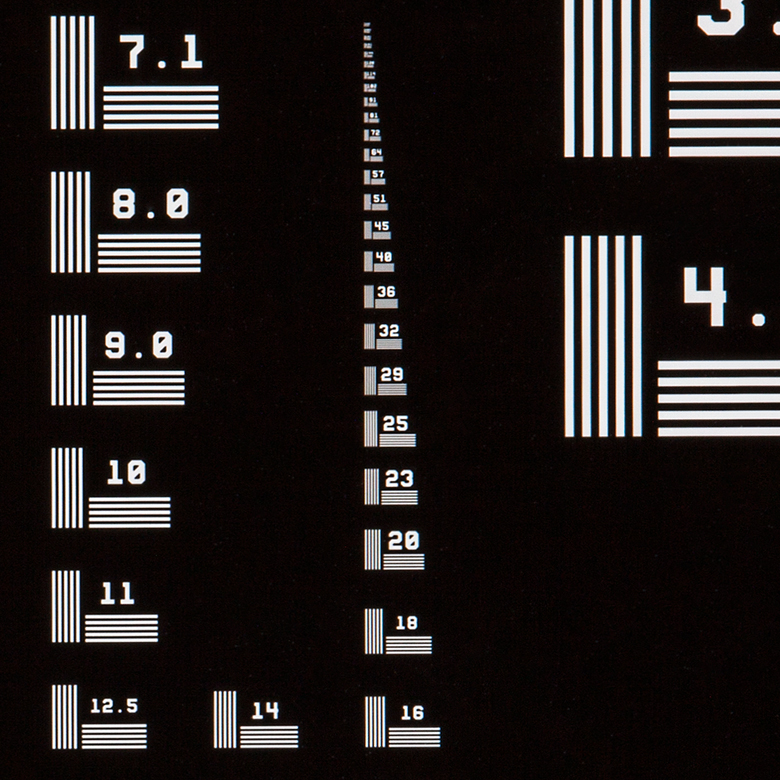
Click for Details
Line sets with frequencies of 32 and 29 cycles/mm on the R2L2S1N1 negative target. The enlarged image shows line sets of 7.1 through 228 cycles/mm.
Click for Details
Line sets with frequencies of 32 and 29 cycles/mm on the R2L2S1P1 positive target. The enlarged image shows line sets of 7.1 through 228 cycles/mm.
| Optical Specifications | ||
|---|---|---|
| Item # | R2L2S1P1 | R2L2S1N1 |
| Pattern | LRa Chrome | Clear |
| Background | Clear | LRa Chrome |
| Surface Flatness | ≤15 µm | |
| Chrome Optical Densityb | ≥3.0 | |
- Frequencies from 1 to 228 cycles/mm (See List Below)
- Determine Resolution of an Optical System
- 2.00" x 2.00" (50.8 mm x 50.8 mm) Soda Lime Glass Substrate
- Positive and Negative Targets Available
Thorlabs' 2.00" x 2.00" (50.8 mm x 50.8 mm) high-frequency NBS 1963A resolution test targets offer 48 line sets with frequencies from 1 to 228 cycles/mm, corresponding to cycle sizes from 1.0 mm to 4.4 µm (see the table below and the Resolution Targets tab for more information). Each set of lines on the pattern contains five horizontal and five vertical lines and is labeled with the frequency of the lines in cycles/mm, as shown in the images to the right. The resolution of an optical system can be determined by identifying the highest frequency line set that the system is able to resolve.
These resolution targets are offered in positive and negative versions. The R2L2S1P1 positive target consists of a low-reflectivity chrome pattern plated on to a clear substrate and is useful for front-lit and general applications. Alternatively, the R2L2S1N1 negative target uses the same low-reflectivity chrome coating to cover the substrate, leaving the pattern itself clear, and works well in back-lit and highly illuminated applications.
|
• |

 Zoom
Zoom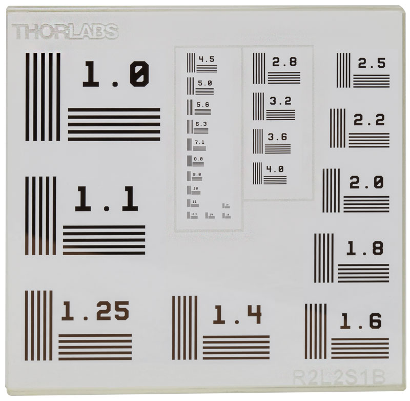
Click for Details
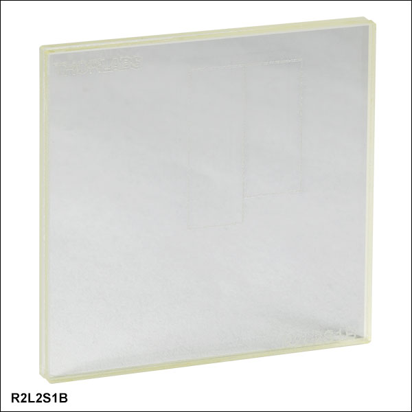
This image depicts the pattern placement relative to the inscribed rectangles on the front of the test target.
Click for Details
Image of R2L2S1B as seen through two crossed wire grid polarizers. The enlarged image shows the positive pattern on the left and negative pattern on the right.
| Optical Specifications | |
|---|---|
| Design | Liquid Crystal Polymer Between N-BK7 Substrate and N-BK7 Protective Glass |
| Substrate Thickness | 2.0 mm (0.08") |
| Protective Glass Thickness | 0.2 mm |
- Determine Resolution of a Polarizing Optical System
- Birefringent Target Displays Both Positive and Negative Patterns
- Frequencies from 1 to 18 cycles/mm (See List Below)
- 2.00" × 2.00" (50.8 mm × 50.8 mm) N-BK7 Glass Substrate
Thorlabs offers a birefringent 2.00" x 2.00" (50.8 mm x 50.8 mm) NBS 1963A resolution test target that is made by sandwiching a birefringent pattern between a glass substrate and protective glass, both made from N-BK7. The test pattern is only observable if the target is placed between a pair of crossed polarizers (see image to the right).
The target is designed so that it can display both positive and negative patterns by adjusting the orientation of the crossed polarizers relative to the test target. If the cross polarizers are aligned with the sides of the glass covers, the positive image will be formed. If the cross polarizers are aligned at 45° to the sides of the glass covers, the negative image will be formed. Because of its polarization sensitivity, this resolution target is ideal for calibrating and testing the resolution of our birefringence imaging system and microscopes, polarizing microscopes, microscopes with a Nomarski mode, polarization imaging systems, or Mueller Matrix polarimeters.
This target has 26 sets of five horizontal and five vertical lines. Each set of lines is labeled with a number, which refers to the number of cycles per mm. With a maximum frequency of 18 cycles/mm, the smallest cycles are only 0.0556 mm. For more information, please see the Resolution Targets tab above. Since the pattern is only visible through crossed polarizers, the target is inscribed with two rectangles for reference. The image on the far right shows the pattern placement with respect to these inscribed rectangles.
|
|

 Zoom
ZoomClick to Enlarge
Close Up of the R1L1S3P Sector Star Pattern
- 1.00" x 1.00" (25.4 mm x 25.4 mm) Positive or Negative Sector Star Targets
- Determine Resolution of an Optical System
- Low-Reflectivity, Vacuum-Sputtered Chrome on Soda Lime Glass
Thorlabs offers four 1.00" (25.4 mm) square targets with Sector star (also known as Siemens star) patterns. Two of the targets (Item #s R1L1S2P and R1L1S3P) have positive patterns, while the other two (Item #s R1L1S2N and R1L1S3N) have negative patterns.
The R1L1S2P and R1L1S2N targets have 36 bars over 360°, and the R1L1S3P and R1L1S3N targets have 72 bars over 360°. Each pattern has a 200 µm inner diameter and a 10 mm outer diameter. On the 36 bar targets, this provides resolutions from 1.2 lp/mm to 57.3 lp/mm, and on the 72 bar targets, resolutions from 2.3 lp/mm to 114.6 lp/mm. The targets can be used to determine the resolution of an optical system by noting how close to the center of the pattern an optical system can to resolve adjacent bars. For more information about sector star patterns, please see the Resolution Targets tab.
| Item # | Pattern | Background | Surface Flatness |
Chrome Optical Density |
Pattern Outer Diameter |
Center Circle Diameter |
Number of Bars |
Resolution at Outer Diameter |
Resolution at Center Circle |
|---|---|---|---|---|---|---|---|---|---|
| R1L1S2P | Low-Reflectivity Chrome |
Clear | ≤15 µm | ≥3.0 at 430 nm | 10 mm | 200 µm | 36 Over 360° | 1.2 lp/mm | 57.3 lp/mm |
| R1L1S2N | Clear | Low-Reflectivity Chrome |
|||||||
| R1L1S3P | Low-Reflectivity Chrome |
Clear | 72 Over 360° | 2.3 lp/mm | 114.6 lp/mm | ||||
| R1L1S3N | Clear | Low-Reflectivity Chrome |

 Zoom
Zoom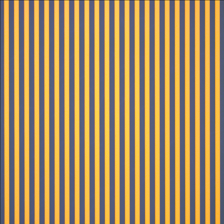
Click to Enlarge
Close Up of R1L3S14N Ronchi Ruling Pattern
| Optical Specifications | |
|---|---|
| Pattern | Alternating Clear and LRa Chrome Lines |
| Border | LR Chrome |
| Surface Flatness | ≤15 µm |
| Chrome Optical Densityb | ≥3.0 |
- 3.00" x 1.00" (76.2 mm x 25.4 mm) Square Wave Ronchi Ruling Target
- Patterns with Spacings from 0.5 lp/mm to 500 lp/mm
- Large 65 mm x 17 mm Clear Aperture
- Determine Resolution, Field Distortion, and Parfocal Stability in an Optical System
- Low-Reflectivity, Vacuum-Sputtered Chrome on Soda Lime Glass
- Compatible with our MLS203 Microscope Stages via MLS203P2 Slide Holder
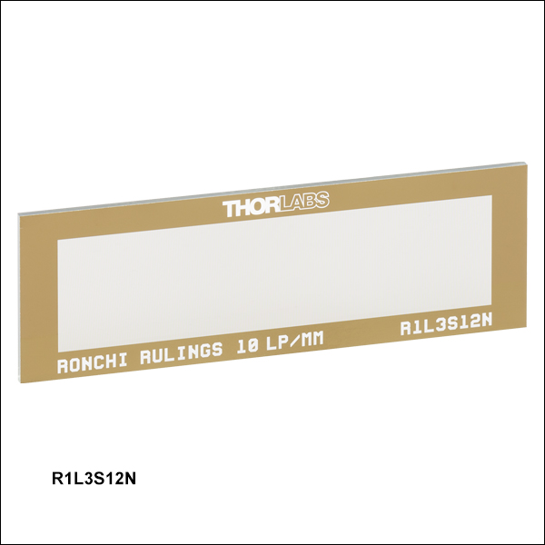
Thorlabs offers Ronchi ruling targets with resolutions ranging from 0.5 line pairs per millimeter (lp/mm) to 500 lp/mm, where a line pair is one dark line and one light line. These square wave, constant-interval bar and space patterns are fabricated from the deposition of a dark low-reflectivity chrome pattern on a 3.00" x 1.00" x 0.06" (76.2 mm x 25.4 mm x 1.5 mm) soda lime glass substrate. This leaves a large 65 mm x 17 mm clear aperture and works well in back-lit and highly illuminated applications. The dimensions of the glass substrate are the same as a standard microscope slide. These Ronchi rulings are excellent for evaluating resolution, field distortion, and parfocal stability in optical systems.

 Zoom
ZoomClick to Enlarge
Close Up of R1L3S6P Variable Line Grating Pattern
| Optical Specifications | ||
|---|---|---|
| Item # | R1L3S6P | R1L3S6PR |
| Pattern | LRa Chrome | LRa Chrome |
| Background | Clear | Chrome |
| Surface Flatness | ≤15 µm | ≤15 µm |
| Chrome Optical Densityb | ≥3.0 | - |
| Chrome Reflectanceb | - | LRa Chrome: <10% Chrome: >40% |
- 3.00" x 1.00" (76.2 mm x 25.4 mm) Variable Line Grating Target
- Resolutions from 1.25 lp/mm to 250 lp/mm
- Determine Resolution of an Optical System
- Vacuum-Sputtered Low-Reflectivity Chrome on Soda Lime Glass
- Compatible with our MLS203 Microscope Stages via MLS203P2 Slide Holder
- High-Contrast Positive Reflective Target Available
Thorlabs offers two 3.00" x 1.00" positive variable line gratings with 18 sections of line grating with resolutions ranging from 1.25 line pairs (one light line and one dark line) per millimeter (lp/mm) to 250 lp/mm. The table below lists each of the available resolutions. The resolution of an optical system can be measured by determining the highest resolution grating with lines that the system is able to resolve.
Thorlabs offers the R1L3S6P positive target composed of a low-reflectivity chrome pattern etched on clear soda lime glass, useful for front-lit and general applications. The R1L3S6PR positive reflective target is composed of a dark low-reflectivity chrome pattern on a chrome background; the high contrast between the pattern and the background makes this target ideal for reflective applications. See the Graphs tab for details.
|
|

 Zoom
Zoom
Click to Enlarge
Close Up of the Smaller Grid on the R3L3S5P Target with Labels Added (See Tables Below)
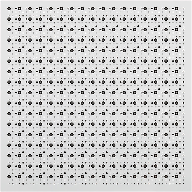
Click to Enlarge
Close Up of Entire Pattern on the R3L3S5P Target
| Optical Specifications | |
|---|---|
| Pattern | LRa Chrome |
| Background | Clear |
| Surface Flatness | ≤15 µm |
| Chrome Optical Densityb | ≥3.0 |
- Concentric Circles and Crosshair Patterns Arranged in a Grid
- Four Different Concentric Circle Sizes and Five Different Crosshair Sizes
- Measure Resolution, Distortion, and Magnification of an Imaging System
- 3.00" x 3.00" (76.2 mm x 76.2 mm) Soda Lime Glass Substrate
Thorlabs' 3.00" x 3.00" (76.2 mm x 76.2 mm) Concentric Circles and Crosshairs Grid Target offers 289 individual grids, arranged in a larger, 2" x 2" grid of 17 rows and 17 columns. The smaller grids each have four concentric circle patterns and five crosshair patterns of varying sizes. The concentric circle and crosshair patterns on the smaller grids are labeled in the image to the right but not on the target itself. Each concentric circle pattern features seven different radii, while the crosshairs each have a single or a double cross. For details on the dimensions of these patterns, see the tables below.
The pattern on this target is made from plating low-reflectivity, vacuum-sputtered chrome on a 0.06" (1.5 mm) thick soda lime glass substrate to achieve an optical density of ≥3 at 430 nm. The dark pattern and clear substrate are useful for front-lit and general applications.
| Concentric Circles | |||||||
|---|---|---|---|---|---|---|---|
| Circle Patterna | R1 | R2 | R3 | R4 | R5 | R6 | R7 |
| A1 | 31.3 µm | 62.5 µm | 125 µm | 140.6 µm | 234.4 µm | 242.2 µm | 500 µm |
| A2 | 15.6 µm | 31.3 µm | 62.5 µm | 70.3 µm | 117.2 µm | 121.1 µm | 250 µm |
| A3 | 7.8 µm | 15.6 µm | 31.3 µm | 35.2 µm | 58.6 µm | 60.5 µm | 125 µm |
| A4 | 3.9 µm | 7.8 µm | 15.6 µm | 17.6 µm | 29.3 µm | 30.3 µm | 62.5 µm |
| Crosshairs | |||
|---|---|---|---|
| Crosshair Patterna | Single or Double Line | Length/Width | Line Widthb |
| B1 | Double | 500 µm | 6.25 µm |
| B2 | Double | 500 µm | 12.5 µm |
| B3 | Single | 500 µm | 50 µm |
| B4 | Double | 500 µm | 25 µm |
| B5 | Double | 500 µm | 100 µm |

 Zoom
Zoom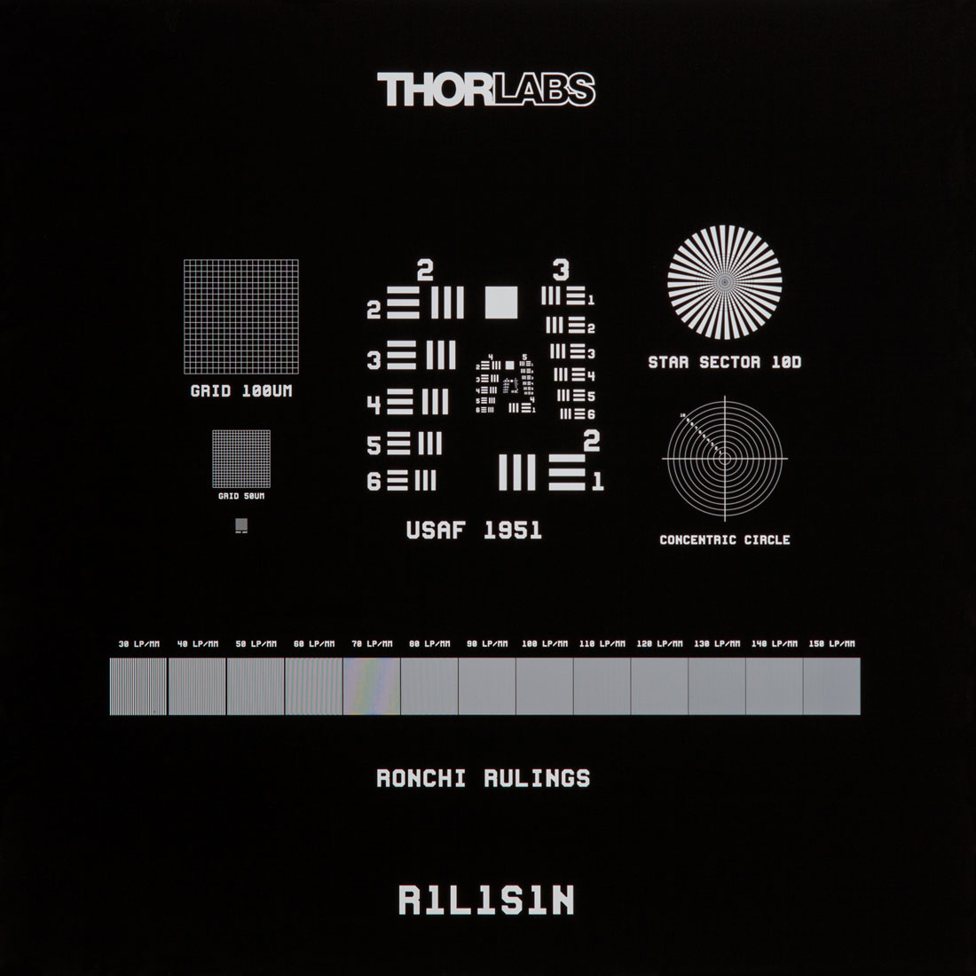
Click to Enlarge
Microscope Image of the R1S1L1N Negative Test Target
| Optical Specifications | ||
|---|---|---|
| Item # | R1L1S1P | R1L1S1N |
| Pattern | LRa Chrome | Clear |
| Background | Clear | LRa Chrome |
| Surface Flatness | ≤15 µm | |
| Chrome Optical Densityb | ≥3.0 | |
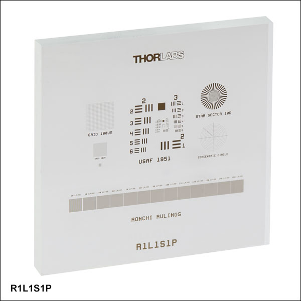
- Measure Image Distortion, Astigmatism, and Other Aberrations
- 18.0 mm (0.71") Square, 1.5 mm Thick Target
- Determine Resolution of an Optical System
- Includes 1951 USAF Pattern, Sector Star, Concentric Circles, Grids, and Ronchi Rulings
- Positive and Negative Targets Available
Thorlabs offers positive and negative 18.0 mm x 18.0 mm x 1.5 mm combined resolution / distortion test targets that are made by low-reflectivity, vacuum-sputtered chrome with an optical density of ≥3 at 430 nm on a soda lime glass substrate. They are ideal for calibration of imaging systems and microscope stages.
The test targets include a 1951 USAF pattern (Groups 2 - 7), a sector star, concentric circles, grids (100 µm, 50 µm, and 10 µm), and Ronchi rulings (30 - 150 lp/mm). These targets are useful for testing resolution, field distortion, focus errors, and astigmatism. The 1951 USAF targets are useful for measuring imaging resolution. For more information, please see the Resolution Targets tab above. The grids can be used to measure image distortion, while the concentric circles are ideal for identifying focus errors, astigmatism, and other aberrations existing in an imaging system. The Ronchi rulings are excellent for evaluating resolution, field distortion, and parfocal stability.
These resolution targets are offered in positive and negative versions. The R1L1S1P positive target consists of a low-reflectivity chrome pattern plated on to a clear substrate and is useful for front-lit and general applications. Alternatively, the R1L1S1N negative target uses the same low-reflectivity chrome coating to cover the substrate, leaving the pattern itself clear, and works well in back-lit and highly illuminated applications.
| Target Feature | Details | Target Feature | Details |
|---|---|---|---|
| 1951 USAF Target | Groups 2 - 7 | Concentric Circles | 10 Circles with Radii from 100 µm to 1000 µm in 100 µm Intervals, Labeled 1 to 10 |
| Grids | 20 x 20 Arrays with 100 µm, 50 µm, and 10 µm Pitch | Ronchi Rulings | 13 Rulings from 30 lp/mma to 150 lp/mm in 10 lp/mm Intervals |
| Sector Star | 36 Bars through 360°, 10 µm Radius Center Circle, and Ten Concentric Circles with Radii from 50 µm to 500 µm in 50 µm Intervals | ||

 Zoom
Zoom|
|
Click to Enlarge
Figure 444A Close Up of R1L3S5P Stage Micrometer
| Optical Specifications | |
|---|---|
| Pattern | LRa Chrome |
| Background | Clear |
| Surface Flatness | ≤15 µm |
| Chrome Optical Densityb | ≥3.0 |
- 3.00" x 1.00" x 0.06" (76.2 mm x 25.4 mm x 1.5 mm) Target
- Includes NBS 1963A Pattern, Sector Star, Concentric Circles, Grids, Ronchi Rulings, and More (See Table 444B)
- Determine Resolution of an Optical System
- Measure Image Distortion, Astigmatism, and Other Aberrations
- Compatible with our MLS203 Microscope Stages via MLS203P2 Slide Holder
The R1L3S5P positive 3.00" x 1.00" x 0.06" (76.2 mm x 25.4 mm x 1.5 mm) combined resolution / distortion test targets that are made by vacuum-sputtering low-reflectivity chrome with an optical density of ≥3 at 430 nm on a soda lime glass substrate. They are ideal for calibration of imaging systems and microscope stages. They are sized to fit in our MLS203P2 stage slide holder for use with our MLS203 microscope stages.
The test targets include an NBS 1963A pattern, a sector (Siemens) star, concentric circles, grids, Ronchi rulings, and more (see Table 444B). These targets are useful for testing resolution, field distortion, focus errors, and astigmatism. The NBS 1963A, sector star, and concentric circle targets are useful for measuring imaging resolution. For more information, please see our Resolution Targets page. The grids can be used to measure the distortion introduced by an imaging system. The Ronchi rulings are excellent for evaluating resolution, field distortion, and parfocal stability.
| Table 444B Specifications | |||
|---|---|---|---|
| Target Feature | Details | Target Feature | Details |
| NBS 1963A | Frequencies from 4.5 cycles/mm to 228 cycles/mm (See List Above) | Concentric Circles | 10 Circles with Radii from 100 µm to 1000 µm in 100 µm Intervals |
| Distortion Grid (Squares) | 3 Grids: 100 lp/mma, 150 lp/mm, 200 lp/mm | Fixed Ronchi Rulings | 3 Rulings:100 lp/mm, 150 lp/mm, and 200 lp/mm |
| Distortion Grid (Dots) | 3 Grids: 400 µm Pitch of Ø80 µm Dots, 200 µm Pitch of Ø 40 µm Dots, 100 µm Pitch of Ø20 µm Dots |
Variable Ronchi Rulings | 20 Rulings (Each 1 mm x 1 mm): 10 lp/mm to 200 lp/mm in |
| Two-Point Resolution Dots | Ø25 µm, Ø20 µm, Ø15 µm, Ø12.5 µm, Ø10 µm, Ø7.5 µm, and Ø5 µm | Pinholes | Ø25 µm, Ø20 µm, Ø15 µm, Ø12.5 µm, Ø10 µm, Ø7.5 µm, and Ø5 µm |
| Interdigitated Lines | 6.25 lp/mm, 12.5 lp/mm, 25 lp/mm, 50 lp/mm, 100 lp/mm, |
Three Micrometers | 1 mm x 1 mm XY Scale with 50 µm Divisions 1 mm Scale with 10 µm Divisions 10 mm Scale with 50 µm Divisions |
| Sector Star | 36 Bars through 360°, 50 µm Radius Center Circle, and Ten Concentric Circles with Radii from 100 µm to 500 µm in 50 µm Intervals | ||