 Products Home
XYZ Microscope Stages
- Ideal for use in 3D Imaging Applications
- Z-Axis Resolution: 25 nm
- Low-Profile, Compact Footprint
- Compatible with Cerna®, Nikon, Olympus, and Zeiss Microscopes
Motorized XYZ Scanning
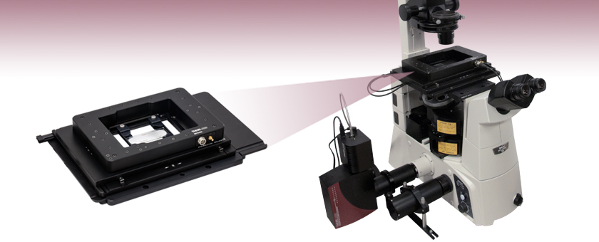
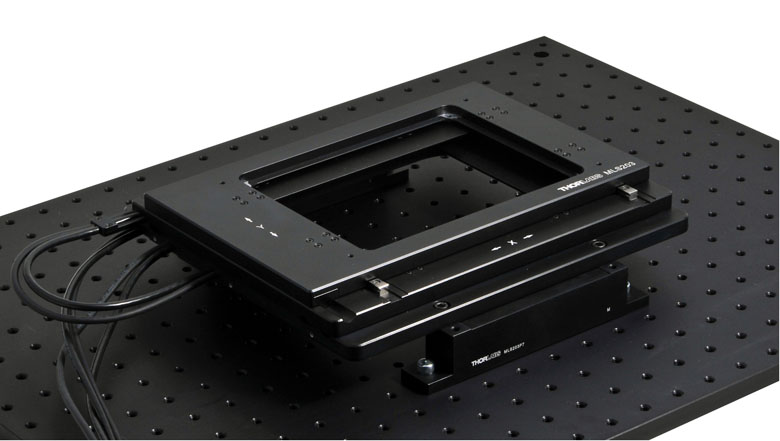
MZS500-E Z-Axis Stage and MLS203-1 XY
Stage Shown with the MZS500P2 Slide Holder
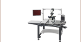
MZS500-E Z-Axis Stage Mounted
to an MLS203-1 XY Microscopy
Stage, Shown Attached to a Nikon
Eclipse Ti-U Microscope


Please Wait

Click to Enlarge
A complete LPXY1/MZS500-E scanning stage configuration is shown with optional MJC1 and MJC2 joysticks. The LPXY1 stage is shown with the finger guard removed.
Features
- Two Low-Profile XY Scanning Stage Options with 110 mm x 75 mm Travel
- Mounting Bracket Available for Thorlabs' Cerna®, Nikon, Olympus, or Zeiss Microscopes
- Z-Axis Piezo Stage with 500 µm of Vertical Travel and 25 nm Resolution
- Mount to Compatible XY Scanning Stage for Complete XYZ Microscope Stage
- XYZ Microscope Stage Specimen Holders and Accessories Available
The MLS203/MZS500-E and LPXY1/MZS500-E motorized XYZ microscope stage systems present 3D positioning solutions for applications such as Z-axis slicing or 3D image collection, including laser scanning microscopy. The MZS500-E features closed-loop, active feedback to ensure correct positioning with submicron repeatability and Z-axis resolution of 25 nm, making the stage ideal for applications that require highly accurate focus control. To build a complete XYZ motorized microscopy stage package, purchase either the MLS203 High-Speed XY Scanning Stage or LPXY1 Low-Profile XY Scanning Stage with its respective controller, the MZS500-E Z-Axis Stage, and appropriate mounting brackets. Optional Z-axis stage accessories can also be purchased below. The table below outlines the items that should be purchased to form a complete XYZ stage package for various microscopes.
XY Scanning Stage
The first component needed to construct the XYZ microscope stage is an appropriate XY scanning stage. The MLS203 scanning stage has has been designed as a drop-in replacement for the manual stage found on select Nikon, Olympus, and Zeiss microscopes or for use with Thorlabs' Cerna microscopes to provide motorized XY positioning of microscopy samples. Characterized by high-speed scanning capabilities and high positional accuracy of <3.0 µm, this compact stage is ideal for manually or automatically positioning a wide range of specimens and samples in many types of microscopy or imaging techniques and applications. Thorlabs also offers the LPXY1 low-profile XY scanning stage for use with Nikon, Olympus, and Thorlabs' Cerna microscopes. This compact stage uses stepper motors to provide optimal low-speed performance with high positioning stability, making it ideal for routine positioning in microscopy. This LPXY1 scanning stage is a robust, cost-effective solution for applications where high-speed is not required.
To incorporate an XY stage into a microscope imaging system, you must use one of the mounting brackets provided below; the type of bracket will be dependent on the microscope being used. Alternatively, we also offer adapters to bolt the XY scanning stage to an optical table or breadboard for use in typical photonics applications or in a custom microscope setup.
Z-Axis Piezo Stage
The MZS500-E Z-Axis Piezo Stage is the second of the two components needed to construct the XYZ microscope stage. This low-profile, piezo-driven stage provides 500 µm of travel in the vertical (Z-axis) direction. The stage is sold with a closed-loop, piezo controller; together, the stage and controller provide computer-controlled Z-axis positioning and active location feedback. To incorporate the stage into the microscope imaging system, it must first be mounted to either a MLS203 XY scanning stage or LPXY1 scanning stage using the provided cap screws. Please refer to the table below to verify which XY stage can mount the MZS500-E Z-axis stage. Once a compatible XY stage is chosen, select the compatible XY stage mounting bracket to incorporate the XYZ stage into your microscope imaging system.
Specimen Holders and Accessories
We offer a range of adapters to allow the positioning of microscope slides, Petri dishes, and mounted metalurgical specimens. TThe MJC2 XY-Axis Joystick is available for both the MLS203 and LPXY1 stages, and the MJC1 Z-Axis Joystick is available for the MZS500 stages. Please see the details below.
Complete XYZ Microscope Stage Assemblies
| Microscopea | XY Stage / Controller | XY Stage Mounting Bracket |
Z-Axis Stageb | Optional Specimen Holders and Accessoriesc |
|---|---|---|---|---|
| Thorlabs Cerna® | MLS203-1 Stage / BBD302 Controllerd or LPXY1 Stage / BSC202 Controller |
CSA1000 | MZS500-E | C4SH01: Multi Slide Holder MZS500P2: Slide/Petri Dish Holder MZS500P3: Blank Adapter Plate MZS500P5: 1/4"-20 Tapped Breadboard Plate MZS500P4: M6-Tapped Breadboard Plate MJC2: XY Microscopy Joystick MJC1: Z-Axis Microscopy Joystick |
| Nikon 50i, 80i, 90i, and Ci-L | MLSA06 | |||
| Nikon TE2000 and Eclipse Ti | MLSA03 | |||
| Nikon Eclipse FN1 | MLSA07 | |||
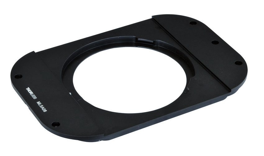
| Olympus BX41, BX43, BX51, and BX61 | MLSA08 | |||
| Olympus IX71, IX73, IX81, and IX83 | MLSA02 | |||
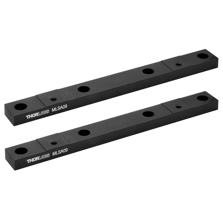
| Olympus IX70 | MLSA09 | |||
| Zeiss Axio Observer and Axiovert 40 | MLS203-2 Stage / BBD302 Controllerd | None Needed | ||
| Optical Breadboard / Custom Configuration | MLS203-1 Stage / BBD302 Controllerd or LPXY1 Stage / BSC202 Controller |
MLSA01 or MLSA04 | ||
| MLS203-2 Stage / BBD302 Controllerd | MLSA04 |
MZS500-E Controller
| Item # | MZS500-E |
|---|---|
| Piezoelectric Output (SMC Male) | |
| Voltage (Software Control) | 0 to 150 VDC |
| Voltage (External Input) | -10 to +10 VDC |
| Current | 500 mA Max Continuous |
| Stability | 100 ppm Over 24 hours (After 30 min Warm-Up Time) |
| Noise | <3 mV RMS |
| Typical Piezo Capacitance | 1 to 20 µF |
| Bandwidth | 1.0 kHz, Digital Closed Loop |
| Position Feedback (9-Pin D-Type Female) | |
| Feedback Transducer Type | Strain Gauge and Capacitive Compatible |
| Detection Method | AC Bridge (18 kHz Excitation) |
| Typical Resolution | 5 nm (for 20 µm Actuator e.g. PAZ005) |
| Auto-Configure | ID Chip in Stage |
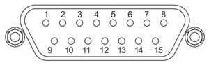
| User Input/Output (15-Pin D-type Female) | |
| 4 Digital Inputs | TTL Levels |
| 4 Digital Outputs | Open Collector |
| Trigger Input/Output | TTL |
| Trigger Input Functionality | Triggered Voltage Ramps/Waveforms |
| Trigger Output Functionality | Trigger Generation During Voltage Ramp Output |
| User 5 V (with Ground) | 250 mA Max |
| Controller Specifications (Main Unit) | |
| Front Panel Controls | |
| Display | 5-Digit, 7-Segment |
| Buttons | Volts/Microns Select, Open/Closed Loop Select, Zero, Resolution |
| Display Brightness | Adjustable |
| Resolution | Switchable Coarse and Fine Adjustment |
| Output | Infinite Turn Precision Digital Potentiometer (Encoder) |
| USB Port | USB 2 Full speed (12Mbps) Compatible |
| Input Power Requirements | |
| Voltage | 85 - 264 VAC |
| Power | 150 W |
| Fuse | 3.15 A |
| General | |
| Dimensions (W x D x H) | 152 mm x 244 mm x 104 mm (6" x 9.6" x 4.1") |
| Weight | 3.18 kg (7 lbs) |
MZS500-E Z-Axis Stage
| Item # | MZS500-E |
|---|---|
| Drive Voltage | 0 to 150 V |
| Travel | 500 µm |
| Resolution | 25 nm |
| Minimum Step Size | 250 nm Typical |
| Feedback Transducer Type | Capacitive |
| Position Linearity Error | < 0.05% over Full Travel |
| Typical Settling Time for 1 to 100 µm Step | 25 ms Typical |
| Max Travel Bandwidth | 10 Hz |
| Drive Signal Shape | Saw Tooth, Sinusoidal or Square Wave |
| Resonant Frequency (± 10%) | 155 Hz at No Load 130 Hz at 100 g Load 110 Hz at 200 g Load 100 Hz at 250 g Load |
| Maximum Loada | 250 g (0.5 lbs) |
| Tilt Angle | X-Axis: ± 50 µrad Y-Axis: ±30 µrad |
| Operating Temperature | 25° C |
| Dimensions (X, Y, Z)b | 8.9" x 5.9" x 0.98" (226 mm x 150 mm x 25 mm) |
| Weight (with cables, no accessories fitted) | 850 g (1.85 lb) |
| Surface Finish | Black Anodized |
Click to Enlarge
Mechanical Drawing Showing the MZS500-E Z-Axis Stage Mounted to the MLS203 XY Scanning Stage
MLS203 XY Scanning Stage
| Item # | MLS203-1/ML203-2 |
|---|---|
| Travel Range | 110 mm x 75 mm (4.3" x 2.95") |
| Speed (Max) | 250 mm/s |
| Acceleration (Max) | 2000 mm/s2 |
| Bidirectional Repeatability | 0.25 µm |
| Unidirectional Repeatability | 0.25 µm |
| Backlasha | N/A |
| Load Capacity (Max)b | 1 kg (2.2 lb) |
| Incremental Movement (Min) | 0.1 µm |
| Absolute On-Axis Accuracy | < 3 µm |
| Percentage Accuracy (Max) | X-Axis: 0.0027% Y-Axis: 0.004% |
| Flatness in X Axis | ±3 µm over full travel, ±1 µm over 10 mm |
| Flatness in Y Axis | ±2 µm over full travel, ±1 µm over 10 mm |
| Home Location Accuracy | 0.25 µm |
| Settling Time within 1 µm (600 g Load) | 0.1 s |
| Settling Time within 0.1 µm (600 g Load) | 0.6 s |
| Weight (Including Cables) | 3.2 kg (7.0 lbs) |
| Limit Switches | X and Y as Standard |
| Bearing Type | Precision Linear Bearing |
| Motor Type | Brushless DC Linear Motor |
| Dimensions (Mid Travel) | 250 mm x 229.3 mm x 31 mm (9.84" x 9.03" x 1.22") |
| Recommended Controller | BBD302 |
BBD302 Controller
| Item # | BBD302 |
|---|---|
| Number of Channels | 2 |
| Drive Connector | 8 Pin DIN, Round, Female |
| Feedback Connector | 15-Pin D-Type, Female |
| Brushless Continuous Output | 2.5 A per Channel, 5 A Max All-Channel Total Output |
| Brushless Peak Output | 4.0 A per Channel, 5 A Max All-Channel Total Output |
| PWM Frequency | 40 kHz |
| Operating Modes | Position and Velocity |
| Control Algorithm | 16-Bit Digital PID Servo Loop with Velocity and Acceleration Feedforward |
| Velocity Profile | Trapezoidal/S-Curve |
| Position Count | 32 Bit |
| Position Feedback | Incremental Encoder |
| Encoder Bandwidth | 2.5 MHz (10 M Counts/sec) |
| Encoder Supply | 5 V |
| AUX Control Connector | 37-Pin D-Type Female (User Digital IO, 5 V O/P) |
| Front Panel Display | 4.3" Full-Color LCD, 480 x 272 Pixels |
| Input Power Requirements |
250 VA Voltage: 100 to 240 VAC Frequency: 47 to 63 Hz Fuse: 3.15 A |
| Dimensions (W x D x H) | 250.0 mm x 279.1 mm x 108.8 mm (9.84" x 10.99" x 4.28") |
| Mass (Weight) | 1.70 kg (3.75 lbs) |
| LPXY1 Stage | |
|---|---|
| Travel Range | 110 mm x 75 mm (4.33" x 2.95") |
| Speed (Max) | 25 mm/s |
| Velocity Stability | <1.27 mm/s |
| Acceleration (Max) | 400 mm/s2 |
| Bidirectional Repeatability | <±1.5 µm |
| Unidirectional Repeatability | <±1.5 µm |
| Minimum Repeatable Incremental Movement | 0.1 µm |
| Calibrated On-Axis Accuracy | <±5.0 µm |
| Home Location Accuracy | <±2.5 µm |
| Load Capacity (Max)a | 1 kg (2.2 lb) |
| Pitch Angular Deviation | ±150 µrad |
| Yaw Angular Deviation | ±150 µrad |
| Horizontal Straightness | ±3 µm |
| Vertical Straightness | ±3 µm |
| Limit Switches | X and Y as Standard |
| Bearing Type | High Rigidity Recirculating Precision Linear Bearing |
| Motor Type | Stepper Motor |
| Step Angle | 1.8° (200 Step Motor) |
| Step Accuracy | 5% |
| Microsteps per Full Step | 2048 |
| Microsteps per Revolution of Motor | 409 600 (For 200 Step Motor) |
| Dimensions (Mid Travel, Excluding Guards) |
310.1 mm x 255.6 mm x 32.3 mm (12.21" x 10.06" x 1.27") |
| Weight (Including Cables) | 3.0 kg (6.6 lbs) |
| Recommended Controller | BSC202b |
| BSC202 Controller | |
|---|---|
| Input and Output | |
| Motor Drive Connector (15-Pin, D-Type Female) |
2-Phase Bipolar Motor Drive Output Differential Quadrature Encoder (QEP) Input Forward, Reverse Limit Switch Inputs Encoder 5 V (with Ground) |
| Control IO Connector (15-Pin, D-Type Female) |
Jog Forward/Back Input (TTL) User Logic Input/Output (TTL) Single-Ended Analog Input (0 - 10 V) User 5 V (with Ground) 100 mA Max Trigger Input/Output (TTL) |
| Motor Resolution | |
| Microsteps per Full Step | 2048 |
| For 200 Step Motor | 409 600 Microsteps/Rev |
| Motor Drive Voltage | 48 V |
| Motor Drive Power | Up to 50 W (Peak) / 25 W (Average) |
| Motor Speeds | Up to 3000 RPM (200 Full Step Motor) |
| Encoder Feedback Bandwidth | 500 KHz (500 000 Counts/s) |
| Input Power Requirementsa | |
| Voltage | 85-264 VAC |
| Power | 200 W (Peak) |
| Fuse | 3.15 A |
| General | |
| Housing Dimensions (W x D x H) | 240 mm x 360 mm x 133 mm (9.5" x 14.2" x 5.2") |
| Weight | 6.7 kg (14.75 lbs) |
| Compatible Motor Specifications | |
| Peak Powers | 15 to 50 W |
| Average Power | 25 W (Max) |
| Step Angle Range | 20° to 1.8° |
| Coil Resistance (Typical) | 4 - 15 Ω |
| Coil Inductance (Typical) | 4 - 15 mH |
| Rated Phase Currents (Typical) | 0.1 - 1 A |
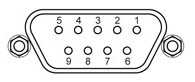
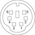
MZS500-E Stage Pin Out Descriptions
Feedback
Male
| Pin | Description | Pin | Description |
|---|---|---|---|
| 1a | Sine + | 7 | Reserved for Future Use |
| 2a | Sine - | 8 | +15 V Supply |
| 3 | Ground | 9 | -15 V Supply |
| 4 | Reserved for Future Use | 10 | Ground |
| 5b | Position + | 11 | Ground |
| 6b | Position - | 12 | Ground |
Drive
SMC Male

0 - 150 V
0 - 500 mA
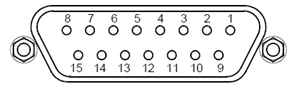
MZS500-E Controller Pin Out Descriptions
Strain Gauge
| Pin | Description | Pin | Description |
|---|---|---|---|
| 1 | Strain Gauge Excitation | 5 | AC Feedback IN |
| 2 | -15 Vouta | 6 | Ground |
| 3 | +15 Vouta | 7 | Actuator ID Signalb |
| 4 | Ground | 8 | Reserved For Future Use |
| 9 | Reserved For Future Use |
User I/O
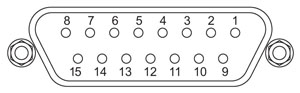
| Pin | Description | Return | Pin | Description | Return |
|---|---|---|---|---|---|
| 1 | Digital O/P 1 | 5,9,10 | 9 | Digital Ground | - |
| 2 | Digital O/P 2 | 10 | Digital Ground | ||
| 3 | Digital O/P 3 | 11 | Reserved for Future Use (Trigger OUT) |
5,9,10 | |
| 4 | Digital O/P 4 | 12 | Reserved for Future Use (Trigger IN) |
||
| 5 | Digital Ground | - | 13 | Digital I/P 4 | |
| 6 | Digital I/P 1 | 5,9,10 | 14 | 5 V Supply Output | |
| 7 | Digital I/P 2 | 15 | 5 V Supply Output | ||
| 8 | Digital I/P 3 |
MLS203 XY Scanning Stage Pin Out Descriptions
Motor Drive
Male
| Pin | Description | Pin | Description |
|---|---|---|---|
| 1 | Motor Phase V | 5 | Stage ID |
| 2 | GND | 6 | GND |
| 3 | Thermistor (Not Used) | 7 | Motor Phase W |
| 4 | Motor Phase U | 8 | Enable |
Encoder Feedback
D-Type Male
| Pin | Description | Pin | Description |
|---|---|---|---|
| 1 | Reserved for Future Use | 9 | GND |
| 2 | GND | 10 | Limit Switch + |
| 3 | Reserved for Future Use | 11 | Limit Switch - |
| 4 | Encoder Index - | 12 | Encoder Index + |
| 5a | QB - | 13a | QB + |
| 6a | QA - | 14a | QA + |
| 7 | 5 V | 15 | Reserved for Future Use |
| 8 | 5 V |
BBD302 Controller Pin Out Descriptions
MOTOR DRIVE
Female DIN Connector
| Pin | Description | Pin | Description |
|---|---|---|---|
| 1 | Motor Phase V | 5 | Stage ID |
| 2 | GND | 6 | GND |
| 3 | Temp. Sensor (Not Used) | 7 | Motor Phase W |
| 4 | Motor Phase U | 8 | Enable |
FEEDBACK
Female D-Type Connector
| Pin | Description | Pin | Description |
|---|---|---|---|
| 1 | Not Connected | 9 | GND |
| 2 | GND | 10 | Limit Switch + |
| 3 | Not Connected | 11 | Limit Switch - |
| 4 | Index - | 12 | Index + |
| 5 | QB - | 13 | QB + |
| 6 | QA - | 14 | QA + |
| 7a | 5 V | 15 | Not Connected |
| 8a | 5 V |
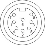
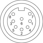
HANDSET
Female Mini DIN Connector
| Pin | Description | Pin | Description |
|---|---|---|---|
| 1 | RX (Controller Input) |
4 | Supply Voltage for Handset 5 V |
| 2 | Ground | 5 | TX (Controller Output) |
| 3 | Ground | 6 | Ground |
AUX I/O
Female D-Type Connector
| Pin | Description | Pin | Description | Pin | Description | Pin | Description |
|---|---|---|---|---|---|---|---|
| 1 | RS232 TX | 11 | User Digital O/P 11+ | 21 | +5 V | 31 | User Digital O/P 4+ |
| 2 | RS232 RX | 12 | User Digital O/P 10- | 22 | User Digital I/P 3 | 32 | User Digital O/P 4- |
| 3 | Ground | 13 | User Digital O/P 10+ | 23 | User Digital I/P 2 | 33 | User Digital O/P 5+ |
| 4 | Differential I/P 2+ | 14 | User Digital O/P 9- | 24 | User Digital I/P 1 | 34 | User Digital O/P 5- |
| 5 | Differential I/P 2- | 15 | User Digital O/P 9+ | 25 | User Digital I/P 0 | 35 | User Digital O/P 6+ |
| 6 | Differential I/P 1- | 16 | User Digital O/P 8- | 26 | User Digital O/P 0 | 36 | User Digital O/P 6- |
| 7 | Differential I/P 1+ | 17 | User Digital O/P 8+ | 27 | User Digital O/P 1 | 37 | Ground |
| 8 | User Digital O/P 12- | 18 | User Digital O/P 7- | 28 | User Digital O/P 2 | - | - |
| 9 | User Digital O/P 12+ | 19 | User Digital O/P 7+ | 29 | User Digital O/P 3 | ||
| 10 | User Digital O/P 11- | 20 | +5 V | 30 | Ground |
USB
Type B USB Female

I/O
Female BNC Connector
5 V TTL
LPXY1 Motorized Scanning Stage Pin Out Descriptions
| Pin | Description | Pin | Description |
|---|---|---|---|
| 1 | Not Connected | 9 | CW Limit Switch |
| 2 | Not Connected | 10 | CCW Limit Switch |
| 3 | Not Connected | 11 | 0 V User |
| 4 | Not Connected | 12 | For Future Use |
| 5 | 5 V User | 13 | For Future Use |
| 6 | Identification | 14 | Motor Phase B+ |
| 7 | Motor Phase B- | 15 | Motor Phase A+ |
| 8 | Motor Phase A- |
Each axis has a 15-Pin D-type connector that is designed to connect to a BSC200 series controller.
BSC200 Series Controller Pin Out Descriptions
Control I/O Connector
| Pin | Description | Return | Pin | Description | Return |
|---|---|---|---|---|---|
| 1 | User 5 V I/O | 9 | 9 | User 0 V | - |
| 2 | Jog Forwardsa | 9 | 10 | Jog Forwardsa | 9 |
| 3 | Not Used | 9 | 11 | Analog Inb | 9 |
| 4 | Trigger In | - | 12 | Trigger Out | 9 |
| 5 | User 0 V | - | 13 | Not Used | 5 |
| 6 | Not Used | - | 14 | Not Used | 6 |
| 7 | Digital (User) In | - | 15 | Digital (User) Out | 9 |
| 8 | Keyed Pin | - |
Motor Drive Connector
| Pin | Description | Pin | Description |
|---|---|---|---|
| 1 | Encoder A +ve | 9 | CW Limit Switch |
| 2 | Encoder A -ve | 10 | CCW Limit Switch |
| 3 | Encoder B +ve | 11 | 0 V User |
| 4 | Encoder B -ve | 12 | For Future Use |
| 5 | 5 V User | 13 | For Future Use |
| 6 | For Future Use | 14 | Motor Phase B+ |
| 7 | Motor Phase B- | 15 | Motor Phase A+ |
| 8 | Motor Phase A- |
Computer Connection
USB Type B
USB Type B to type A Cable Included
| Pin | Description |
|---|---|
| 1 | RX (Controller Input) |
| 2 | Ground |
| 3 | Ground |
| 4 | +5V, 100 mA Power Supply |
| 5 | TX (Controller Output) |
| 6 | Ground |
Thorlabs offers two platforms to drive our wide range of motion controllers: our Kinesis® software package or the legacy APT™ (Advanced Positioning Technology) software package. Either package can be used to control devices in the Kinesis family, which covers a wide range of motion controllers ranging from small, low-powered, single-channel drivers (such as the K-Cubes™ and T-Cubes™) to high-power, multi-channel, modular 19" rack nanopositioning systems (the APT Rack System).
The Kinesis Software features .NET controls which can be used by 3rd party developers working in the latest C#, Visual Basic, LabVIEW™, or any .NET compatible languages to create custom applications. Low-level DLL libraries are included for applications not expected to use the .NET framework. A Central Sequence Manager supports integration and synchronization of all Thorlabs motion control hardware.

Kinesis GUI Screen
APT GUI Screen
Our legacy APT System Software platform offers ActiveX-based controls which can be used by 3rd party developers working on C#, Visual Basic, LabVIEW™, or any Active-X compatible languages to create custom applications and includes a simulator mode to assist in developing custom applications without requiring hardware.
By providing these common software platforms, Thorlabs has ensured that users can easily mix and match any of the Kinesis and APT controllers in a single application, while only having to learn a single set of software tools. In this way, it is perfectly feasible to combine any of the controllers from single-axis to multi-axis systems and control all from a single, PC-based unified software interface.
The software packages allow two methods of usage: graphical user interface (GUI) utilities for direct interaction with and control of the controllers 'out of the box', and a set of programming interfaces that allow custom-integrated positioning and alignment solutions to be easily programmed in the development language of choice.
A range of video tutorials is available to help explain our APT system software. These tutorials provide an overview of the software and the APT Config utility. Additionally, a tutorial video is available to explain how to select simulator mode within the software, which allows the user to experiment with the software without a controller connected. Please select the APT Tutorials tab above to view these videos.
Software
Kinesis Version 1.14.47
The Kinesis Software Package, which includes a GUI for control of Thorlabs' Kinesis and APT™ system controllers.
Also Available:
- Communications Protocol
Software
APT Version 3.21.6
The APT Software Package, which includes a GUI for control of Thorlabs' APT™ and Kinesis system controllers.
Also Available:
- Communications Protocol
The APT video tutorials available here fall into two main groups - one group covers using the supplied APT utilities and the second group covers programming the APT System using a selection of different programming environments.
Disclaimer: The videos below were originally produced in Adobe Flash. Following the discontinuation of Flash after 2020, these tutorials were re-recorded for future use. The Flash Player controls still appear in the bottom of each video, but they are not functional.
Every APT controller is supplied with the utilities APTUser and APTConfig. APTUser provides a quick and easy way of interacting with the APT control hardware using intuitive graphical control panels. APTConfig is an 'off-line' utility that allows various system wide settings to be made such as pre-selecting mechanical stage types and associating them with specific motion controllers.
APT User Utility
The first video below gives an overview of using the APTUser Utility. The OptoDriver single channel controller products can be operated via their front panel controls in the absence of a control PC. The stored settings relating to the operation of these front panel controls can be changed using the APTUser utility. The second video illustrates this process.
APT Config Utility
There are various APT system-wide settings that can be made using the APT Config utility, including setting up a simulated hardware configuration and associating mechanical stages with specific motor drive channels. The first video presents a brief overview of the APT Config application. More details on creating a simulated hardware configuration and making stage associations are present in the next two videos.
APT Programming
The APT Software System is implemented as a collection of ActiveX Controls. ActiveX Controls are language-independant software modules that provide both a graphical user interface and a programming interface. There is an ActiveX Control type for each type of hardware unit, e.g. a Motor ActiveX Control covers operation with any type of APT motor controller (DC or stepper). Many Windows software development environments and languages directly support ActiveX Controls, and, once such a Control is embedded into a custom application, all of the functionality it contains is immediately available to the application for automated operation. The videos below illustrate the basics of using the APT ActiveX Controls with LabVIEW, Visual Basic, and Visual C++. Note that many other languages support ActiveX including LabWindows CVI, C++ Builder, VB.NET, C#.NET, Office VBA, Matlab, HPVEE etc. Although these environments are not covered specifically by the tutorial videos, many of the ideas shown will still be relevant to using these other languages.
Visual Basic
Part 1 illustrates how to get an APT ActiveX Control running within Visual Basic, and Part 2 goes on to show how to program a custom positioning sequence.
LabVIEW
Full Active support is provided by LabVIEW and the series of tutorial videos below illustrate the basic building blocks in creating a custom APT motion control sequence. We start by showing how to call up the Thorlabs-supplied online help during software development. Part 2 illustrates how to create an APT ActiveX Control. ActiveX Controls provide both Methods (i.e. Functions) and Properties (i.e. Value Settings). Parts 3 and 4 show how to create and wire up both the methods and properties exposed by an ActiveX Control. Finally, in Part 5, we pull everything together and show a completed LabVIEW example program that demonstrates a custom move sequence.
Part 1: Accessing Online Help
Part 2: Creating an ActiveX Control
Part 3: Create an ActiveX Method
Part 4: Create an ActiveX Property
Part 5: How to Start an ActiveX Control
The following tutorial videos illustrate alternative ways of creating Method and Property nodes:
Create an ActiveX Method (Alternative)
Create an ActiveX Property (Alternative)
Visual C++
Part 1 illustrates how to get an APT ActiveX Control running within Visual C++, and Part 2 goes on to show how to program a custom positioning sequence.
MATLAB
For assistance when using MATLAB and ActiveX controls with the Thorlabs APT positioners, click here.
To further assist programmers, a guide to programming the APT software in LabVIEW is also available here.
Thorlabs' Kinesis® software features new .NET controls which can be used by third-party developers working in the latest C#, Visual Basic, LabVIEW™, or any .NET compatible languages to create custom applications.
C#
This programming language is designed to allow multiple programming paradigms, or languages, to be used, thus allowing for complex problems to be solved in an easy or efficient manner. It encompasses typing, imperative, declarative, functional, generic, object-oriented, and component-oriented programming. By providing functionality with this common software platform, Thorlabs has ensured that users can easily mix and match any of the Kinesis controllers in a single application, while only having to learn a single set of software tools. In this way, it is perfectly feasible to combine any of the controllers from the low-powered, single-axis to the high-powered, multi-axis systems and control all from a single, PC-based unified software interface.
The Kinesis System Software allows two methods of usage: graphical user interface (GUI) utilities for direct interaction and control of the controllers 'out of the box', and a set of programming interfaces that allow custom-integrated positioning and alignment solutions to be easily programmed in the development language of choice.
For a collection of example projects that can be compiled and run to demonstrate the different ways in which developers can build on the Kinesis motion control libraries, click on the links below. Please note that a separate integrated development environment (IDE) (e.g., Microsoft Visual Studio) will be required to execute the Quick Start examples. The C# example projects can be executed using the included .NET controls in the Kinesis software package (see the Kinesis Software tab for details).
 |
Click Here for the Kinesis with C# Quick Start Guide Click Here for C# Example Projects Click Here for Quick Start Device Control Examples |
|
LabVIEW
LabVIEW can be used to communicate with any Kinesis- or APT-based controller via .NET controls. In LabVIEW, you build a user interface, known as a front panel, with a set of tools and objects and then add code using graphical representations of functions to control the front panel objects. The LabVIEW tutorial, provided below, provides some information on using the .NET controls to create control GUIs for Kinesis- and APT-driven devices within LabVIEW. It includes an overview with basic information about using controllers in LabVIEW and explains the setup procedure that needs to be completed before using a LabVIEW GUI to operate a device.
 |
Click Here to View the LabVIEW Guide Click Here to View the Kinesis with LabVIEW Overview Page |
|
| Posted Comments: | |
Ik Hwan Kwon
(posted 2021-09-20 11:20:20.11) Hello,
Our MZS500-E has problem that it couldn't zero-positioning.
When push the Zero positioning button,
The position value is -35.2432 um and Maximum voltage
I thought that this problem comes from positioning sensor calibration (green plate).
But, It doesn't has any feedback even manual file :)
How can I fix this problem? DJayasuriya
(posted 2021-09-21 03:49:30.0) Thank you for your inquiry. We will get in touch with you directly to troubleshoot. jinjie pan
(posted 2021-06-01 10:52:56.903) 我们从你们这里购买了MZS500-E这器材,但是我们自己不小心将其附带的接线弄丢了,还希望你们可以提供一下这个器材和控制器的接线的型号,我们好在购买一下,一根电源线我们型号找到了,但是另一根反馈线我们型号找不到,还希望你们可以提供一下,谢谢,希望得到您的回复。 cwright
(posted 2021-06-02 09:20:55.0) Response from Charles at Thorlabs: Thank you for your query. A member of your local technical support team will reach out to help provide the cables you have misplaced. laura.waller
(posted 2014-01-07 18:47:01.677) We can only get this working with matlab Active X if we use a 32 bit PC. Who uses 32 bits these days?!? Isn't there a 64 bit automation option that will interface with Matlab? msoulby
(posted 2014-01-08 04:36:40.0) Response from Mike at Thorlabs: We are currently developing a 64bit software platform to replace our now old APT software which will be 64bit compatible. We are currently in an alpha test phase but hope to have an advanced beta version in the near future that we can send to customers to use. However you can use direct serial communication over a virtual comm port in order to talk directly to the controller on a 64bit machine. I have contacted you directly with details of the USB communication protocols we use and more details on its use. kelvin.wc.poon
(posted 2013-07-15 15:15:41.773) This is a follow to the question below.
Does the max load for the stage (250g) include the weight of the accessory plates? We have weighed the latter and they are around 200g, leaving only 50g for our samples.
Another concern is the single spring/tension being the only point of contact for the plates. Any rapid XY movement makes the plate shift slightly. Is there a way to improve the stability? pbui
(posted 2013-07-18 11:39:00.0) Response from Phong at Thorlabs: Thank you for your feedback. The absolute weight limit of the stage is 250g, so your sample should be 50g or less. Regarding the stability, as we mention in a note in the manual on page 13, heavier loads may be unstable. We would recommend using a lower acceleration with a profiled stop to avoid this issue. cbrideau
(posted 2013-06-24 21:08:06.623) Does the 250g weight limit of the MZS500 stage include the weight of the inserts such as the MZS500P4? bdada
(posted 2011-11-03 11:33:00.0) Response from Buki at Thorlabs:
We appreciate your interest in our microscopy stages and your positive feedback about our products. We can certainly arrange for you to test our products. We have contacted you to continue this conversation. gcolarus
(posted 2011-11-02 22:39:11.0) Hi,
I am very interested in purchasing your automated microscope stage (both x,y and piezo z) products as well as your filter wheels/shutters.
I notice that they are compatible with Micromanager from the Vale website. However, I can't seem to track down a group that is using your stages with MM.
Can you comment on the compatibility with MM or put me in contact with groups that have these stage components running in their labs with MM? How about Volocity or Metamorph? If possible, we would greatly appreciate a loaner unit and we could prepare a complete report as we have lots of experience with imperfect automated stages (companies shall remain un-named for now).
I am keen because I have been buying different components from Thor and have not been disappointed.
Pina Colarusso
Live Cell Imaging Facility
UCalgary |

 Zoom
Zoom| Key Stage Specificationsa | |
|---|---|
| Travel Range | 110 mm x 75 mm (4.3" x 2.95") |
| Velocity (Max) | 250 mm/s |
| Acceleration (Max) | 2000 mm/s2 |
| Bidirectional Repeatability | 0.25 µm |
| Unidirectional Repeatability | 0.25 µm |
| Horizontal Load Capacity (Max)b | 1.0 kg (2.2 lb) |
| Min Achievable Incremental Movement | 0.1 µm |
| Home Location Accuracy | 0.25 µm |
| Absolute On-Axis Accuracy | <3 µm |
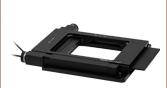
- XY Scanning Component of the Motorized XYZ Microscope Stage System
- Integrates with Cerna®, Nikon, Olympus, and Zeiss Upright and Inverted Microscopes
- Recommended Controller: BBD302 Dual-Axis Brushless DC Servo Motor Controller (Sold Separately)
- Optional MJC2 Joystick Sold Separately Below
- Integrated Brushless DC Linear Servo Motor Actuators
- Linear Optical Encoders
- High-Quality, Precision-Engineered Linear Bearings
- High Repeatability (0.25 µm) and Position Accuracy (<3 µm)
The MLS203 high-speed scanning stage is one option for an XY scanning stage that can be used to build the XYZ stage system with the MZS500-E Z-axis piezo stage. The MLS203/MZS500-E stage system forms a versatile 3D translation stage for scanning across a sample with high precision in the X, Y, and Z axes. The MLS203-1 Stage is compatible with inverted and upright microscopes from Nikon and Olympus, as well as with upright Thorlabs Cerna microscopes; mounting brackets are required (sold below). The MLS203-2 Stage is directly compatible with Zeiss Axio Observer and Axiovert 40 microscopes; mounting brackets are not required. Please note that the LPXY1 low-profile scanning stage is another option for an XY scanning stage to build the XYZ stage system (sold below) and has identical microscope compatibility to the MLS203-1.
The recommended controller for the MLS203 XY scanning stages is the BBD302 Two-Channel Controller, which features Thorlabs' Kinesis® control and programming interface, enabling easy integration into automated microscopy applications. This controller is ideal for applications demanding operation at high speeds (hundreds of mm/s) and high encoder resolution (<100 nm). For greater flexibility, communication with the PC is supported using either a USB or RS232 interface.
The controller is supplied with a software development kit (SDK) in order to also support automated PC control of the MLS203 stages. This is useful to system integrators and other automation specialists who need to combine operation of the stage with other microscopy automation accessories. The fully documented SDK supports all major development languages running on Windows, such as LabVIEW, C++, and MATLAB, and comes in the form of ActiveX libraries or a conventional dynamic link library (DLL). Multiple units can be connected to a single PC using a USB hub; for example, the BBD302 Controller for the MLS203 XY stages and the controller supplied with our MZS500-E Z-Axis Stage Kit can be controlled simultaneously with a single PC. Please click here to view the full presentation for these Brushless DC Motor Controllers.

 Zoom
Zoom| Key Stage Specificationsa | |
|---|---|
| Travel Range | 110 mm x 75 mm (4.3" x 2.95") |
| Velocity (Max) | 25 mm/s |
| Acceleration (Max) | 400 mm/s2 |
| Bidirectional Repeatability | <±1.5 µm |
| Unidirectional Repeatability | <±1.5 µm |
| Horizontal Load Capacity (Max)b | 1 kg (2.2 lb) |
| Min Achievable Incremental Movement | 0.1 µm |
| Home Location Accuracy | <±2.5 µm |
| Calibrated On-Axis Accuracy | <±5.0 µm |
- XY Scanning Component of the Motorized XYZ Microscope Stage System
- Integrates with Cerna®, Nikon, and Olympus Upright and Inverted Microscopes
- Recommended Controller: BSC202 Two-Channel Benchtop Stepper Motor Controller (Sold Separately)
- Optional MJC2 Joystick Sold Separately Below
- Compact Design with Easy Sample Access
- High-Quality, Precision-Engineered Linear Bearings
- Ideal for Routine Positioning in Microscopy
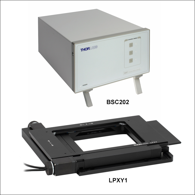
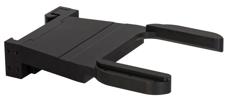
The LPXY1 motorized scanning stage is one option for an XY scanning stage that can be used to build the XYZ stage system with the MZS500-E Z-axis piezo stage. The LPXY1 scanning stage uses stepper motors with open-loop control to provide a compact, reliable, and cost-effective solution for low-speed XY positioning applications. When combined with the MZS500-E Z-axis piezo stage, the LPXY1 scanning stage forms a versatile 3D translation stage for scanning across a sample with high precision in the X, Y, and Z axes. This stage is compatible with inverted and upright microscopes from Nikon and Olympus, as well as with upright Thorlabs Cerna microscopes; mounting brackets are required (sold below). Please note that the MLS203 high-speed scanning stage is another option for an XY scanning stage to build the XYZ stage system (sold above).
The recommended controller for the LPXY1 scanning stage is the BSC202 Two-Channel Benchtop Stepper Motor Controller. It features Thorlabs' Kinesis® control and programming interface, enabling easy integration into automated microscopy applications. This controller features USB connectivity, a fully featured Graphical User Interface (GUI) panel, and an extensive software support suite that includes a number of out-of-the-box user utilities, allowing for immediate operation of the unit without any detailed pre-configuration. A fully featured ActiveX® programming environment is also included to facilitate custom application development in a wide range of programming environments, such as LabVIEW, C++, and MATLAB. Multiple units can be connected to a single PC via standard USB hub technology; for example, both the BSC202 controller for the LPXY1 stage and the controller supplied with our MZS500-E Z-Axis Piezo Stage Kit can be operated simultaneously with a single PC. For more details on the BSC202 controller, please see the full presentation for our benchtop stepper motor controllers.
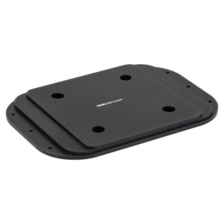
Click to Enlarge
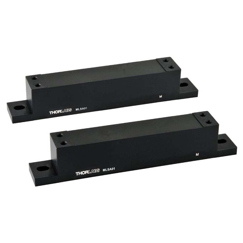
MLS203-1 Stage Attached to a Breadboard with our MLSA01 Bracket Set
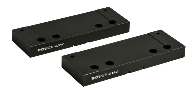
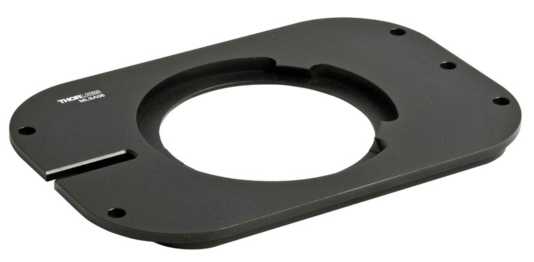
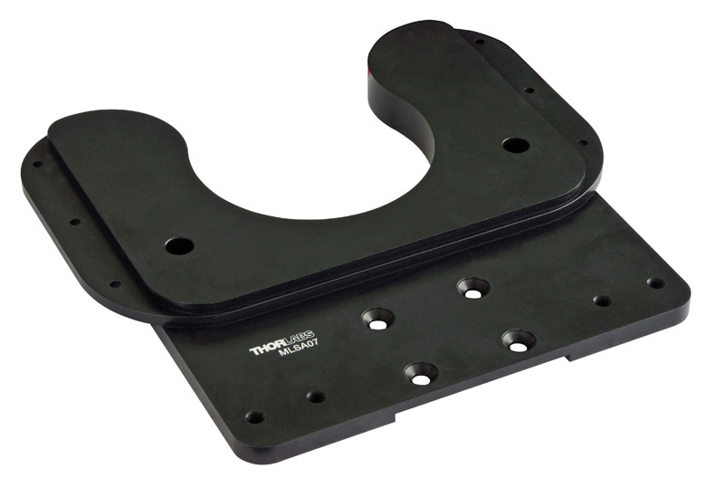
We offer a choice of brackets to facilitate mounting the MLS203-1 and LPXY1 stages to a range of upright and inverted microscopes from Thorlabs, Nikon, and Olympus. Please see the table below for specific compatibility. Each bracket (with the exception of the CSA1000) comes with instructions describing how to attach the stage to the microscope. Please note that the MLS203-2 is directly compatible with Zeiss Axio Observer and Axiovert 40 microscopes. Mounting brackets are not required.
Additionally, there are two options for attaching an MLS203 or LPXY1 stage to an imperial or metric breadboard to support home-built microscopes or general photonics applications. The MLSA01 Riser Plates, compatible with stage Item # MLS203-1 and LPXY1, will raise the height of the stage by 1.24" (31.5 mm). The MLSA04 Adapter, compatible with stage Item #s MLS203-1 and MLS203-2, connects to the base of the stage, blocking the central aperture; however, it raises the height of the stage by only 0.03" (0.7 mm), making it well suited for height-limited applications.
| Click Image for Details |
 |
 |
 |
 |
 |
 |
 |
 |
 |
| Item # | CSA1000 | MLSA02 | MLSA09 | MLSA08 | MLSA03 | MLSA06 | MLSA07 | MLSA01 | MLSA04 |
| Stage Item # | MLS203-1 or LPXY1 | MLS203-1 or LPXY1 | MLS203-1 or LPXY1 | MLS203-1 or LPXY1 | MLS203-1, MLS203-2, or LPXY1 |
||||
| Microscope Brand | Thorlabs | Olympus | Nikon | Optical Breadboard, Custom Configuration |
|||||
| Microscope Model | Cerna® | IX71, IX73, IX81, IX83 |
IX70 | BX41, BX43, BX51, BX53, BX61 |
TE2000, Eclipse Ti |
50i, 80i, 90i, Ci-L |
Eclipse FN1 | N/A | |
| Microscope Type | Upright | Inverted | Inverted | Upright | Inverted | Upright | Upright | N/A | |
| We support microscopes from Olympus, Nikon, Zeiss and Leica. Please contact Technical Support to inquire about bracket availability if your microscope model is not listed above. |

 Zoom
Zoom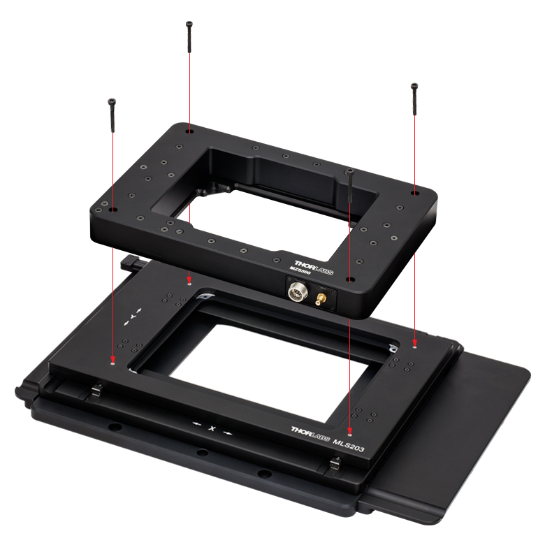
Click to Enlarge
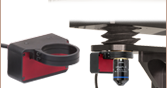
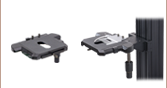
MZS500-E Z-Axis Piezo Stage Being Attached to the Motorized XY Scanning Stage
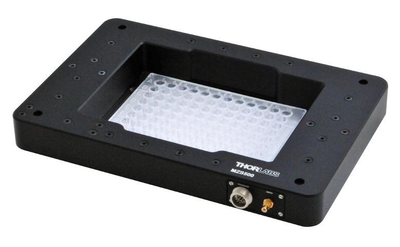
Click to Enlarge
MZS500-E Z-Axis Piezo Stage with Multiwell Plate Fitted
| Key Stage Specifications | |
|---|---|
| Travel Range | 500 µm |
| Resolution | 25 nm |
| Minimum Step Size | 250 nm (Typical) |
| Settling Time for 1 to 100 µm Step | 25 ms (Typical) |
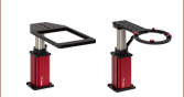
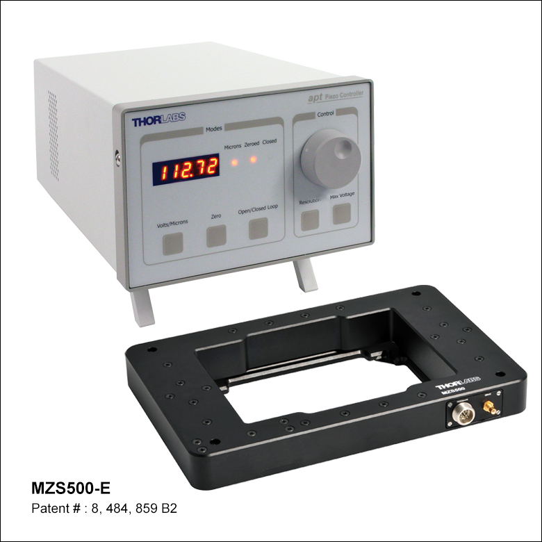
- Includes the Z-Axis Piezo Stage and Controller
- Z-Axis Piezo Stage:
- Z-Axis Component of the Motorized XYZ Microscope Stage System
- Must First be Mounted to the MLS203 XY Stage (See Photo to Right)
- Accessories, Such as Sample Plates and MJC1 Joystick, are Sold Below
- Controller:
- Quiet, High-Resolution Position Control
- High Power: 150 V, 500 mA Continuous
- Full Software Control Suite Supplied
- Software Integrated with Other APT™ Family Controllers (Integrated Systems Development)
- Closed-Loop PID Position via Capacitive Feedback Circuit
- Voltage Ramp/Waveform Generating Capability
(for Scanning Applications) - User-Controlled Digital I/O Port
The MZS500-E Z-axis stage and controller bundle includes a Z-axis stage and a closed-loop piezo controller. The piezo-driven stage provides 500 µm of vertical (Z-axis) travel, 25 nm of resolution, and a 0.5 lb (0.25 kg) max load capacity. The bundle includes everything needed for computer-controlled, Z-axis positioning and active location feedback. Please see the Specs tab for more information on the Z-axis piezo stage.
To incorporate the Z-Axis Stage into a system, it must first be mounted to an MLS203 series XY stage (shown to the upper far right). These two products combined present a versatile 3D solution for translating samples over a long range or across a sample with high precision. The stage can also be directly fitted with a multiwell plate (shown to the upper right); additional accessories can be found below.
The controller included with the stage is a single-channel, high-power (150 V, 500 mA), benchtop piezo controller for open- and closed-loop nanometer position control. Flexible software settings make this controller suitable for driving a wide range of third-party piezo products. In addition, USB connectivity provides easy plug-and-play PC operation; multiple units can be connected to a single PC via a standard USB hub for multi-axis motion control applications. Coupling this with the user-friendly APT™ software allows the user to quickly get up and running. Advanced custom motion control applications and sequences are also possible using the extensive ActiveX® programming environment. These ActiveX Controls can be incorporated into a wide range of software development environments including Labview, C++, and Matlab. Please see the Specs tab for more information on the Z-axis stage controller.
MZS500P5 and MZS500P4 Breadboards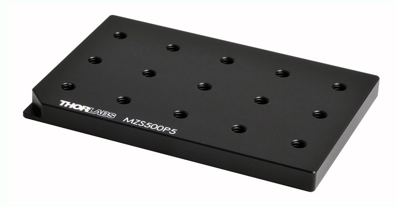
Click to Enlarge
- MZS500P5: 15 x 1/4"-20, 1" Pitch
- MZS500P4: 15 x M6, 25 mm Pitch
C4SH01 Multi Slide Holder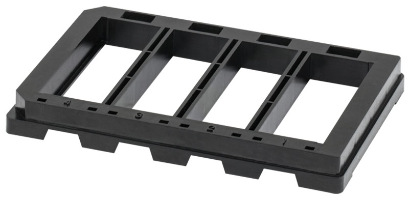
Click to Enlarge
- Plastic Holder Compatible with 25 mm x 75 mm, 1.1 ± 0.2 mm Thick Microscope Slides
- Does Not Hold 26 mm x 76 mm Slides Sold by Thorlabs
- Mount up to Four Slides for Automated Tissue and Tissue Microarray Analysis
- Same Footprint as Multiwell Plates (127.6 mm × 85.5 mm)
MZS500P2 Slide/Petri Dish Holder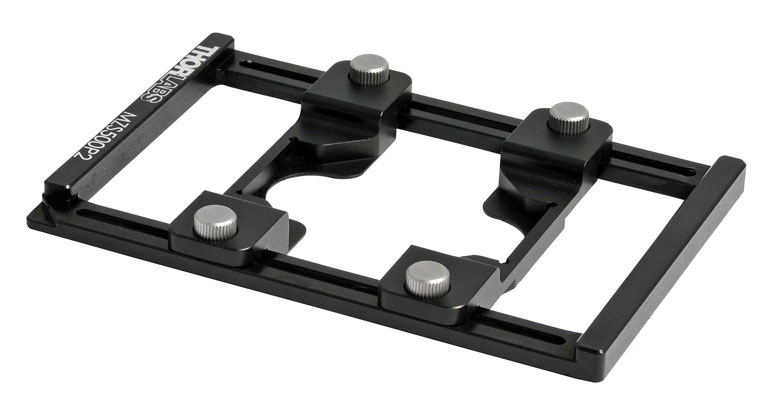
Click to Enlarge
- Compatible with Microscope Slides Measuring 25 mm to 25.4 mm (0.98" to 1.0") in Width
- Compatible with Petri Dishes
- Does Not Hold 26 mm x 76 mm Slides Sold by Thorlabs
- Measuring 30 mm to 60 mm (1.18" to 2.36") in Diameter
- Can be Used with Imperial or Metric Accessories
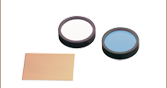
MZS500P3 Blank Adapter Plate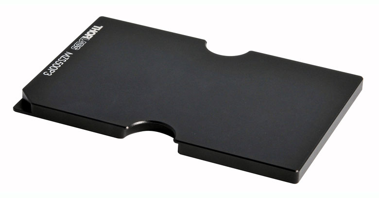
Click to Enlarge
- Ideal for Custom Applications
- Easily Drilled and Tapped
Breadboard Plate Application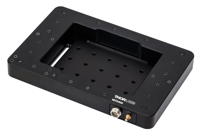
Click to Enlarge
MZS500P5 Mounted in the MZS500-E Z-Axis Stage
Multi Slide Holder Application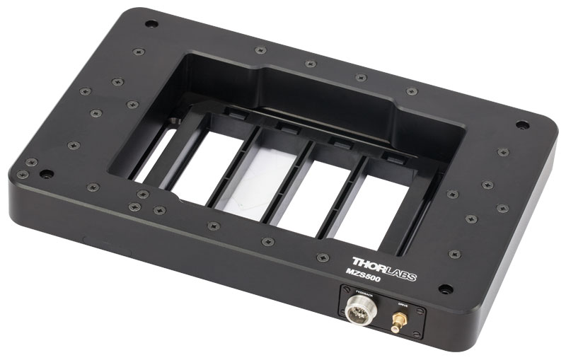
Click to Enlarge
C4SH01 Slide Holder Tray Mounted in the MZS500-E Z-Axis Stage
Slide/Petri Dish Application
Click to Enlarge
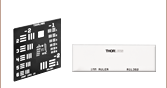
MZS500P2 Slide/Petri Dish Holder Mounted in the MZS500-E Z-Axis Stage with the Stage Micrometer
Blank Adapter Plate Application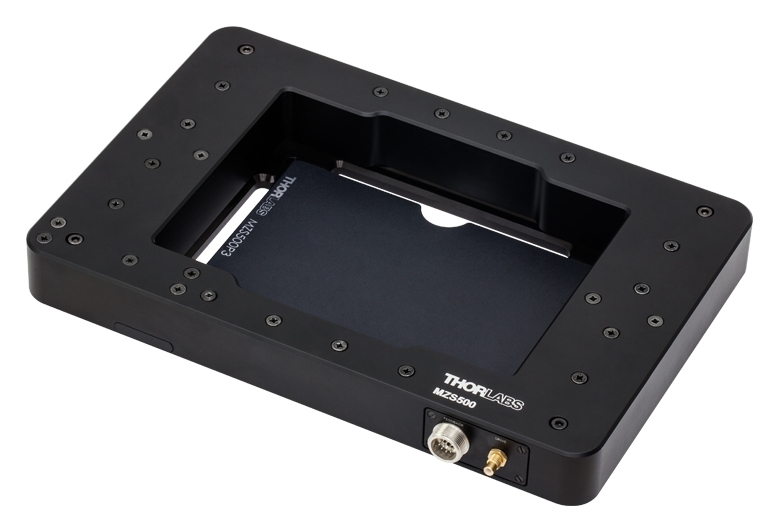
Click to Enlarge
MZS500P3 Mounted in the MZS500-E Z-Axis Stage

 Zoom
Zoom- Ideal for use with MLS203 and LPXY1 Scanning Stages
- High-Reliability Joysticks Utilizing USB HID Protocol
- 2-Axis Control Via a Joystick Knob
- Two Different Modes for Fast or High Precision Moves
- Speed Dial for Sensitivity Adjustment
- Allows Remote Manual Control
- Can be Reprogrammed using a PC
- Ergonomic Design
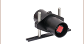
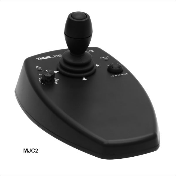
The MJC2 Joystick Console has been designed for microscope users and provides intuitive, tactile, manual positioning of the MLS203, LPXY1, and other XY translation stages. The console features a two-axis joystick for XY control. In most applications, the default parameter settings saved within the controller allow the joystick to be used out-of-the-box, with no need for further setup, thereby negating the requirement to be connected to a host PC and allowing true remote operation. Parameter settings can also be reprogrammed and saved to a paired controller using a PC, allowing the controller to be disconnected from the computer and remote operation continued.
The MJC2 Joystick is compatible with our Benchtop Brushless DC Servo Controllers, Rack-Mounted Brushless Controller, Rack-Mounted Brushless Controller Module and Stepper Motor Controllers. The joystick has both a Mini-DIN and a USB Type-C port and is shipped complete with two cables, a 6-pin Mini-DIN plug to plug cable and a USB 3.1 Type-A to Type-C cable, for use with these controllers as well as setups utilizing the USB HID class. For more information about configuring and setting up the joystick over USB HID, please see the manual by clicking on the red Docs icon ( ) below. If you intend to use the joystick with a legacy BBD10x series unit, please contact Tech Support for a compatible cable.

 Zoom
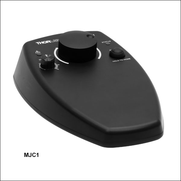
Zoom- Ideal for use with MZS500-E Stage
- High-Reliability Joystick Utilizing USB HID Protocol
- Single-Axis Control Via an Encoder Knob
- Two Different Modes for Fast or High-Precision Moves
- Speed Dial for Sensitivity Adjustment
- Allows Remote Manual Control
- Can be Reprogrammed using a PC
- Ergonomic Design
The MJC1 joystick console has been designed for microscope users to provide intuitive, tactile, manual positioning of the MZS500 stage. It is used in conjunction with the MZS500-E controller above. The console features an encoder knob for single axis control, a push button to switch between fast or high-precision movement, and a speed dial to fine tune speed control. For most applications, the default parameter settings saved with the compatible controller allow the joystick to be used out-of-the-box, with no need for further setup, negating the requirement to be connected to a host PC and allowing true remote operation. Furthermore, the parameter settings can be reprogrammed and saved (persisted) to the controller using a PC, and the joystick then disconnected for continued remote operation.
The MJC1 Joystick is compatible with our BPC30x Series Benchtop Piezo Controllers, including the MZS500-E controller. The joystick has both a Mini-DIN and a USB Type-C port and is shipped complete with two cables, a 6-pin Mini-DIN plug to plug cable and a USB 3.1 Type-A to Type-C cable, for use with these controllers as well as setups utilizing the USB HID class. For more information about configuring and setting up the joystick over USB HID, please see the manual by clicking on the red Docs icon () below.