 Products Home
FiberPort Collimators / Couplers
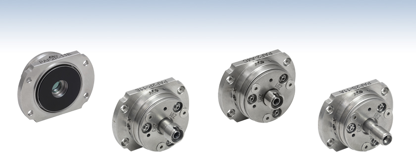
- Ultrastable Micropositioning Alignment with Five Degrees of Freedom Plus Rotation Adjustment
- Usable with Single Mode, Multimode, and Polarization-Maintaining Fiber
- Aspheric or Achromatic Lens
- Models Available for 350 nm - 5 µm
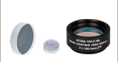
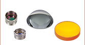
PAF2P-11E
Aspheric FiberPort,
FC/PC, 2.0 - 5.0 µm AR Coating
PAF2-A4C
Achromatic FiberPort,
FC/PC and FC/APC,
1050 - 1620 nm AR Coating
PAF2S-11A
Aspheric FiberPort,
SMA, 350 - 700 nm AR Coating
Back
Front


Please Wait
| FiberPort Quick Links | |||
|---|---|---|---|
| Item # | Lens Type | Connector | EFLs (mm) |
| PAF2-Ax | Cemented Achromatic Doublet |
FC/PC & FC/APC | 4, 7.5 |
| PAF2P-Ax | FC/PC | 10, 15 | |
| PAF2A-Ax | FC/APC | 10, 15 | |
| PAF2S-Ax | SMA | 4, 7.5 | |
| PAF2-x | Molded Aspheric Lens |
FC/PC & FC/APC | 2, 4, 4.6, 7.5 |
| PAF2P-x | FC/PC | 11, 15.3, 18.4 | |
| PAF2A-x | FC/APC | 2, 4.6, 7.5, 11, 15.3, 18.4 |
|
| PAF2S-x | SMA | 2, 4.6, 7.5, 11, 15.3, 18.4 |
|
Click to Enlarge
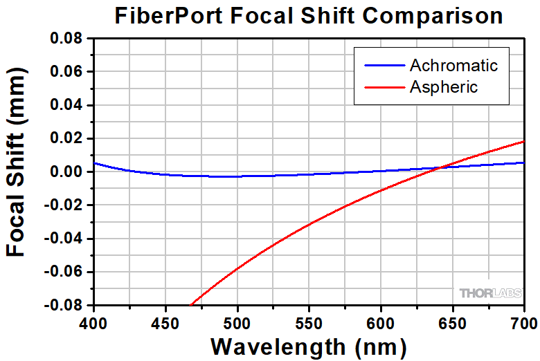
Comparison of Focal Shifts in Achromatic and Aspheric FiberPorts
(-A Coated Versions Shown)
Features
- Five Degrees of Freedom Plus Rotational Adjustment
- Low Hysteresis (See Graphs Tab for More Information)
- FC/PC, FC/APC, and SMA Versions
- FC/PC and FC/APC Versions Accept Both 2.1 mm Wide Key and 2.0 mm Narrow Key Connectors
- SMA FiberPorts Are Designed for SMA905 Connectors
- Available with Either an Achromatic Doublet or an Aspheric Lens
- Suitable for Single Mode (SM), Multimode (MM), and Polarization-Maintaining (PM) Fiber
- AR Coating Options for Visible, NIR, and MIR Wavelength Ranges (See
Selection Guide Tab for Details)
Thorlabs' compact, ultrastable FiberPort micropositioners provide an easy-to-use platform for coupling light into and out of optical fibers. Their compact size; repeatable, high-resolution alignment mechanism; high thermal stability*; and translation locking mechanisms (detailed in the Operation tab) make these FiberPorts an ideal solution for long- or short-term fiber coupling and collimation. Each FiberPort is factory-aligned for collimation at the wavelength specified in its respective mechanical drawing, which can be found by clicking on the red document icon (![]() ) below. For information about the hysteresis and thermal stability, please see the Graphs tab.
) below. For information about the hysteresis and thermal stability, please see the Graphs tab.
Each FiberPort includes an achromatic doublet or aspheric lens with an effective focal length ranging from 2.0 mm to 18.4 mm. They are available with FC/PC, FC/APC, or SMA fiber bulkheads. For applications that are compatible with short effective focal lengths (≤7.5 mm), we offer FiberPorts with FC bulkheads that can be used with both FC/PC and FC/APC connectors. Their 5-axis adjustment combined with their short focal length leads to negligible off-axis sensitivity. For more details on how to select a FiberPort, please see the Selection Guide tab.
For a higher maximum theoretical coupling efficiency, we recommend using FiberPorts with our AR-coated single mode, multimode, or polarization-maintaining fiber optic patch cables for coupling and collimating light, as these patch cables reduce back reflections from high powered sources. For FiberPorts being used in the mid-infrared spectral region, we recommend our fluoride fiber patch cables.
Achromatic FiberPorts
Our achromatic FiberPorts collimate light over a large wavelength range with a very small focal length shift. This reduces the need for realignment if the wavelength of the source is changed. The focal length shift for both the achromatic and similar aspheric FiberPorts can be seen in the Selection Guide tab above. These FiberPorts are available with an effective focal length of 4.0 mm, 7.5 mm, 10 mm, or 15 mm. The EFL shift for each achromatic FiberPort can be viewed in the tables below. Additional information about achromatic doublet performance can be seen here.
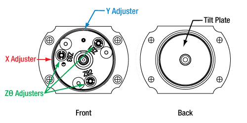
Five Degrees of Freedom (Plus Bulkhead Rotation)
While holding the connector and fiber stationary, the built-in lens can be aligned with five degrees of freedom: linear alignment of the lens in X and Y, angular alignment for tip and tilt, and Z adjustment using the tip and tilt controls simultaneously. The travel range of the aspheric lens in the X and Y direction is ±0.7 mm with a resolution of 317 µm per revolution. The travel range in the Z direction is ±1.0 mm with resolution of 200 µm per revolution. In addition, the three flat-head screws on the front plate can be loosened to enable rotation of the bulkhead for PM fiber alignment. After alignment is complete, a locking setscrew on the side of the housing can be tightened to secure the X and Y position, as can the locking collars on the Zθ adjusters to lock the tip/tilt position. See the Operation tab for complete details on operating a FiberPort.
Mounting Options
FiberPorts contain four #2 counterbores that provide mechanical compatibility with our FiberBench accessories. We have also developed adapters for using FiberPorts with Ø1/2" posts, 30 mm cage systems, and HeNe lasers. Please see the FiberPort Mounts tab for more information.
Included Hardware
These FiberPorts include a dust cap, a 0-80 locking screw, a 0.028" hex key for the locking screw, a 0.050" hex key for the Zθ, X, and Y adjusters, and an SPW403 spanner wrench for the Zθ locking collars.
*Please note the maximum recommended temperature for operation is 80 °C.
External SM1 Threading
For integration into many of our optomechanical components, the FiberPort has an SM1 (1.035"-40)external threading.
Locking Collars
The locking collars on the Zθ adjusters fix the alignment position using the included spanner wrench. The collars can be locked without affecting even single mode alignments. They also prevent overtravel of the Zθ adjuster screws.Matched Material CTEs
The materials used have matched coefficients of thermal expansion (CTEs) to ensure optimal thermal performance. Additionally, the lens cell and tilt plate are made of hardened stainless steel for additional stability.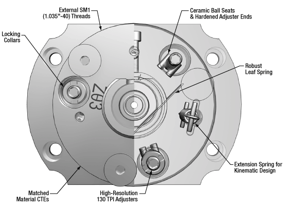
External (Left) and Internal (Right) FiberPort Features
Ceramic Ball Seats & Hardened Adjuster Ends
The long-wearing ceramic ball seats and the hardened adjuster ends ensure a secure fit and thermal stability.Robust Leaf Spring
The new leaf spring geometry reduces the risk of a bent leaf spring, ensuring repeatable and consistent travel in X and Y while minimizing hysteresis.Kinematic Design
The extension springs follow the dowel-and-spring design of our kinematic mounts, making the adjustments more repeatable and consistent.130 TPI Adjusters
The high-resolution adjusters allow for fine translation of the tilt plate.Additional Information
Click on the boxes below for more details.
These FiberPorts are especially designed to counteract common misalignment errors in an optical setup, namely temperature-induced hysteresis and crosstalk. Hours of extensive research, multiple design efforts using sophisticated design tools, and months of rigorous testing went into choosing the best components that allow the FiberPort to provide ultra-stable performance. Please see the Graphs tab for more information.
Because the temperature in most labs fluctuates, all mounts in an alignment-sensitive optical setup must intrinsically minimize any thermally induced misalignments. Stainless steel, with its low coefficient of thermal expansion, was chosen to compose the FiberPort to minimize these effects. Additionally, the lens cell and tilt plate are made of hardened stainless steel for additional durability.
In order to minimize positional drift and backlash, it is necessary to limit the amount of play in the adjusters, as well as the amount of lubricant used. When an adjustment is made to an actuator, the lubricant is displaced out of some places to build up in others. This non-equilibrium distribution of lubricant will slowly relax back into an equilibrium state. However, this process may cause the tilt plate to move. The FiberPort uses adjusters matched to the body that exceed all industry standards, so very little adjuster lubricant is needed. As a result, the FiberPort's alignment is extremely stable even after being adjusted. In addition, these adjusters have a smooth feel that allows the user to make small, repeatable adjustments.
These FiberPorts feature a longer leaf spring than the previous generation of FiberPorts, lowering the risk of a bent spring. This also provides a more consistent counterforce against the lens cell, making translation of the lens cell in the X and Y directions more predictable while allowing for full travel.
Adjustments in the Z or Zθ direction use high-resolution 130 TPI adjusters, allowing for fine movements. Additionally, there is an integrated travel limit for these adjusters, preventing overtravel that can force the lens cell off the X and Y adjusters.
Crosstalk is minimized by carefully controlling the dimensional tolerances, material properties, and finish of the components. Standard metal-to-metal actuator contact points will wear down over time; to prevent this, ceramic seats are used at all three contact points between the tilt plate and actuators. These ceramic seats, in conjunction with the hardened stainless steel actuator tips, maintain the integrity of the contact surfaces over time.
While not necessary for most applications in a lab setting, the position of the lens cell and the tilt plate can be locked. The lens cell can be locked by using the included locking screw. The tilt plate's position can be fixed by tightening the Zθ locking collars; this prevents the adjusters from being turned so the tilt plate cannot be translated. Single mode alignment is maintained when using these collars.
Our standard kinematic mounts utilize a dowel-and-spring and ball bearing design for adjustments. This allows for consistent and repeatable movement. The FiberPorts are similarly constructed; they have extension springs to actuate the tilt plate, as well as robust ball seats and adjuster ball ends.
The outer diameter of the FiberPort has SM1 (1.035"-40) threading that is compatible with many of our optomechanical components, including SM1 lens tubes and a variety of fixed mounts. If desired, the FiberPort can be secured into one of these components by the use of SM1 threaded retaining rings.
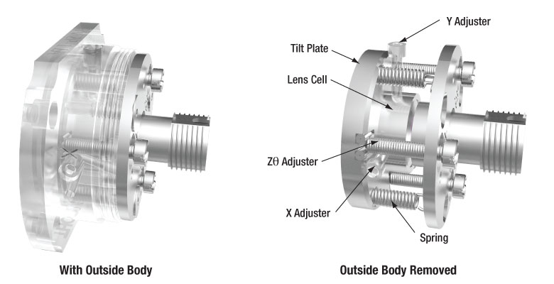
Click to Enlarge
Internal Mechanism of the FiberPort With and Without the Outer Body Removed
X-Y Adjustment
| Specifications | |
|---|---|
| Screw Size | 0-80 |
| Hex Size | 0.05" (1.3 mm) |
| Adjustment per Revolution | 317 µm |
| Translation Range | ±0.7 mm |
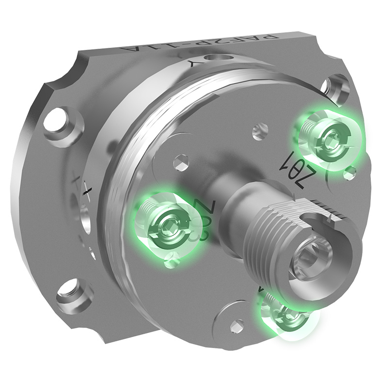
The magnetic lens cell (MLC) can be translated in X-Y, independently from the tilt plate, using the socket head cap screws (SHCS) in the side of the FiberPort body, highlighted in red and blue above. Each adjuster is labeled as X and Y for easy and quick identification. The travel range of the lens in the X and Y directions is ±0.7 mm. See the above table for additional specifications for our X-Y adjuster screws. Note that when a FiberPort is used in a standard collimation or coupling application, only a small portion of this translation range is needed.
X-Y translation is performed independently from angular and Z-axis adjustments. The lens cell, which is magnetically attached to the tilt plate, rests on a leaf spring that provides a counterforce. The resistance of the adjustments made with these screws can be changed using the X-Y tension adjusters discussed below; each adjuster has been highlighted with the same color as its tension adjuster here. The X-Y motion can be locked in place using the locking screw discussed below.
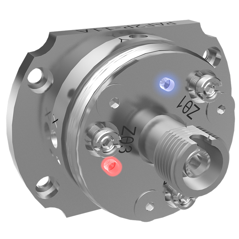
Zθ Adjustment
| Specifications | |
|---|---|
| Screw Size | M2 x 0.2 |
| Hex Size | 0.05" (1.3 mm) |
| Adjustment per Revolution |
200 µm |
| Translation Range | ±1.0 mm |
Each FiberPort consists of a lens cell that is magnetically adhered to a tilt plate. This tilt plate is actuated using three Zθ adjusters, highlighted in green above. Each adjuster is labeled with Zθ1, Zθ2, or Zθ3 so it is easy to tell which adjuster has been or will be adjusted. Turning each adjuster in equal increments enables Z-translation along the optical axis of the FiberPort. The Z-axis translation range is ±1.0 mm. See the above table for additional specifications for our Zθ adjuster screws.
Once final adjustments are made, the position of the tilt plate can be locked via the included locking collars and SPW403 spanner wrench. These adjusters are lockable while maintaining single mode alignment.
The mechanics behind translation of the tilt plate is very similar to the dowel-and-spring construction of our kinematic mounts. Each adjuster has a hardened steel ball-end that rides in a ceramic ball seat. Both the ball-end and ceramic seat are attached using a high temperature, low outgassing epoxy to provide a stable, long wearing kinematic system. The extension springs provide counterforce against the fine adjust screws.
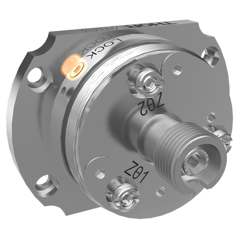
X-Y Lock
| Specifications | |
|---|---|
| Screw Size | 0-80 |
| Hex Size | 0.05" (1.3 mm) |
A setscrew on the bottom of the Fiberport can be used to retain the position of the X and Y adjustment screws. Most applications do not require locking the FiberPort. For example, if the FiberPort is in a low-vibration environment than the locking screw does not need to be engaged.
However, for situations where the FiberPort might undergo large vibrations or shock, such as shipping, the setscrew should be engaged. Using the locking screw can affect coupling; follow all applicable directions in the FiberPort manual when using the locking feature. Note that this locking screw is included but not installed when the FiberPort is shipped.
X-Y Tension
| Specifications | |
|---|---|
| Screw Size | 0-80 |
| Hex Size | 0.028" (0.7 mm) |
Each X-Y adjuster can have its tension adjusted using the corresponding tension screws on the face of the FiberPort. By tightening the tension of an adjuster, it is easier to make small adjustments to the MLC without overshooting the desired position. Conversely, loosening the tensions makes it easier to make large adjustments without applying excessive force.
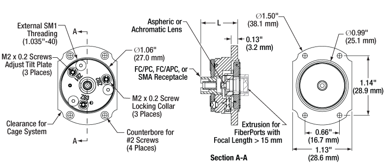
The L in the above mechanical drawing calls out the overall length from the front of the FiberPort, minus the connector bulkhead, to the front face of the mounting flange. This value depends on the focal length and the connector bulkhead. See the tables below for the exact length of each FiberPort.
AR Coatings
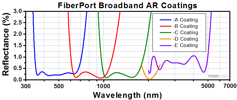
Click to Enlarge
Each FiberPort lens is available with -A (350 - 700 nm or 400 - 700 nm), -B (600 - 1050 nm or 650 - 1050 nm),
-C (1050 - 1620 nm or 1050 - 1700 nm), -D (1.8 - 2.4 µm), or -E (2.0 - 5.0 µm) coating. Please refer to the tables below for the specific wavelength range of each FiberPort lens.
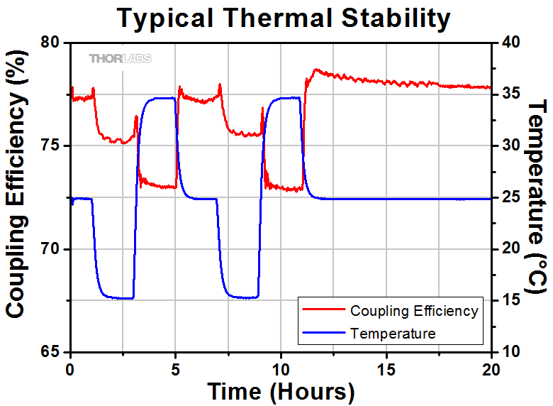
Thermal Stability
The thermal stability of the FiberPort was measured by changing the temperature of the environment by ±10 °C, and measuring the coupling efficiency as it varied with the temperature. These measurements were taken using a PAF2P-11A and PAF2P-11A on an FB-38 FiberBench. A 635 nm source was used with single mode fiber. Please note that the thermal stability depends highly on the components and system setup.
Results:
The ~5% change in coupling efficiency is a result of the movement of all components in this FiberBench/FiberPort system. This change results in approximately 0.5 µm movement of the beam spot relative to the fiber core. After the temperature has changed, upon returning to the original temperature, the coupling efficiency returns to within 1% of the original value.
 Click to Enlarge
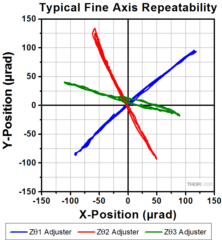
Fine Axis Repeatability
The repeatability of the Zθ adjustments was measured by translating the Zθ adjusters by 200-300 µrad and returning to the starting position at approximately (0,0). This was done three times. To measure this movement, a beam emitted from the FiberPort was transmitted to a CCD beam profiler. These measurements were done with the PAF2P-11A with an input wavelength of 635 nm.
Results:
As seen in the graph to the right, these FiberPorts exhibit good repeatability and low hysteresis. These values are typical and will change based on the selected wavelength and focal length of the FiberPort.

Introduction
Before selecting a FiberPort, it is crucial to consider:
- The wavelength of your source,
- The fiber type (single mode, multimode, or polarization maintaining),
- The fiber connector (FC/PC, FC/APC, or SMA), and
- The desired lens type (achromatic or aspheric).
With this information, it is possible to find what FiberPort is most compatible with your configuration. The method below illustrates the best way to find a FiberPort to use for coupling. This example considers a single mode fiber as the fiber that is being coupled. The calculations needed to determine whether a FiberPort is compatible with a single mode fiber are more complex than with a multimode fiber, which primarily considers the NA of the fiber and the lens.
Click the button to the right to download a macro-enabled Excel file that can assist in finding the best FiberPort for your coupling application. For additional questions, please contact Tech Support.
Calculating the Effective Focal Length
Example:
- Wavelength: 633 nm
- Fiber: P1-630A-FC-2
- Collimated Beam Diameter Prior to Lens: Ø3 mm
The specifications for the P1-630A-FC-2, 633 nm, FC/PC single mode patch cable indicate that the 1/e2 mode field diameter (MFD) is 4.3 μm at 633 nm. The MFD should equal the diffraction-limited spot size Øspot, which is given by the following equation:
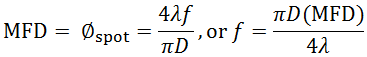
Here, f is the focal length of the lens, λ is the wavelength of the input light, and D is the 1/e2 diameter of collimated beam incident on the lens. Solving for the desired focal length of the collimating lens yields:
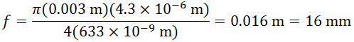
Thorlabs offers a large selection of FiberPorts. You'll note that the FiberPort with a focal length closest to 16 mm has a focal length of 15.3 mm (Item # PAF2P-15A), while also meeting the requirements for fiber connector type and antireflection coating range. This FiberPort also has a clear aperture that is larger than the collimated beam diameter. Therefore, this is the best option given the initial parameters (i.e., a P1-630A-FC-2 single mode fiber and a collimated beam diameter of 3 mm).
For optimum coupling, the spot size of the focused beam must be less than the MFD of the single mode fiber. As a result, if a FiberPort is not available that provides an exact match, then choose the FiberPort with a focal length that is shorter than the calculation above yields. Alternatively, if the clear aperture of the lens is large enough, the beam can be expanded before the lens, which has the result of reducing the spot size of the focused beam.
Please note that the NA values in the specification tables below are the numerical apertures of the lenses, not the required numerical aperture of the fiber you are using. As long as the lens NA is smaller than the NA of your fiber, you should be able to couple light. Please note that if your collimated beam diameter is smaller than the clear aperture of the lens you will need to recalculate the NA using the beam diameter. For best results, Thorlabs recommends using the equations above when choosing a FiberPort, or to use the calculator linked above.
Selecting a Lens
When selecting a FiberPort, it is essential to ensure that the lens included in the FiberPort is compatible with your setup. In particular, the wavelength of the laser source must fall within the AR coating range of the lens, and the spot radius and focal shift should perform in such a way that is beneficial to your system.
AR Coatings
The lenses in Thorlabs’ FiberPorts use our -A (350 - 700 nm or 400 - 700 nm), -B (600 - 1050 nm or 650 - 1050 nm), -C (1050 - 1620 nm or 1050 - 1700 nm), -D (1800 - 2400 nm), or -E (2000 - 5000 nm) AR coatings. The plot to the right shows the typical per-surface reflectance of each AR coating. Each AR-coated lens is housed in a FiberPort package designed to be compatible with FC/PC-, FC/APC-, or SMA-terminated fibers. Care should be taken in selecting a FiberPort to make sure the correct fiber/connector/FiberPort combination is selected. AR-coating information and connector compatibility for each FiberPort are outlined in the tables below. Contact Tech Support for assistance.
Note: The C coating wavelength range specification was recently updated from 1050 - 1620 nm to 1050 - 1700 nm. All optics in stock currently have a C coating with a wavelength range of 1050 - 1700 nm. However, we are in the process of updating our documentation, and so some individual optics may still be presented with the old wavelength range on our website.
Aspheric vs. Achromatic FiberPort Performance
Thorlabs' achromatic FiberPorts utilize cemented doublets designed to minimize chromatic aberrations, making them ideal for collimating broadband light sources or sources with multiple discrete wavelengths. The small focal length shifts experienced by an achromatic doublet allow the FiberPort to be used over a broad wavelength range without the need for realignment (see the Graphs tab for more details).
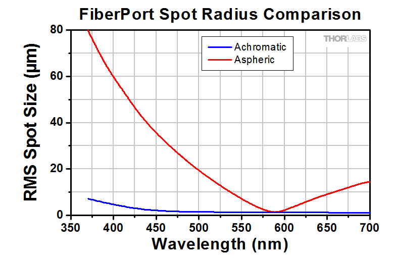
Click to Enlarge
The performance of the achromatic doublet used in an achromatic FiberPort is compared to the aspheric lens used in a FiberPort with the same effective focal length, for a collimated beam focused onto a fiber. The lens is aligned to focus the light onto the fiber at 580 nm. Over a given wavelength range, the achromatic doublet produces a focused spot on the fiber, while the aspheric lens produces a series of wavelength dependent foci along its optical axis due to chromatic focal shift. Since the fiber's position was fixed at the focus of the aspheric lens, the spot size changed drastically with wavelength. However, appropriate adjustment of the fiber’s position as the wavelength is changed can minimize this effect.
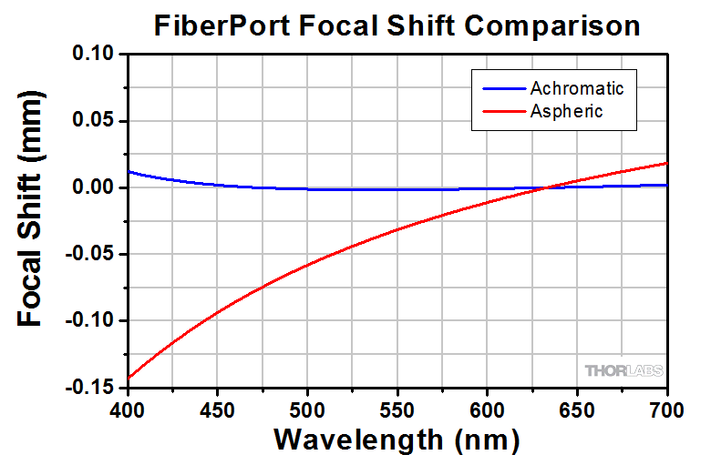
Click to Enlarge
This graph represents the focal length shift for the same setup described in the plot to the left. Both lenses have a similar focal length (F) at ~580 nm. Overall, the focal shift experienced by the aspheric lens in the range 475 nm - 655 nm (except ~580 nm) is approximately an order of magnitude larger than that of the achromatic doublet. For wavelengths less than 580 nm, the beam comes to a focus at a distance < F and longer wavelengths are focused at a distance > F.
Alignment Procedures
All FiberPorts contain a lens cell magnetically attached to a tilt plate that can be adjusted directly in the X and Y directions. Tip/Tilt adjustments along the optical axis are made by incremental adjustments of the Zθ adjusters, marked Zθ1, Zθ2, and Zθ3. These adjusters actuate the tilt plate. Translation in the Z-axis is made by uniformly turning the Zθ adjusters. We recommend using a low-power, visible alignment laser in all of the following adjustments.
The sections below provide recommendations on how to use your FiberPort based on your application. Regardless of application, the Pre-alignment section should be read first. Please note that your FiberPort comes collimated for a specific wavelength as provided in their mechanical drawings, which can be found below by clicking on the red document icon:![]() . After pre-aligning your FiberPort, the Collimating with a FiberPort section provides instructions on how to use your FiberPort as a collimator, while the Coupling into Fiber via FiberPort section provides instructions on how to couple single mode or multimode fiber using your FiberPort.
. After pre-aligning your FiberPort, the Collimating with a FiberPort section provides instructions on how to use your FiberPort as a collimator, while the Coupling into Fiber via FiberPort section provides instructions on how to couple single mode or multimode fiber using your FiberPort.
Pre-alignment

Click to Enlarge
The tilt plate must be orthogonal to the beam axis for optimal alignment.
Before attempting to collimate or couple fiber with your FiberPort, it is crucial to ensure that the FiberPort is properly aligned in such a way that the tilt plate is orthogonal to the beam axis. If alignment is not done, coupling efficiencies will be lower than optimal, regardless of care taken later in the alignment process. If your FiberPort has been adjusted since purchase or requires collimation at a different wavelength, please follow the steps below to provide the best performance.
Aligning the Tilt Plate
With the laser off, center the lens by eye in the tilt plate aperture by turning the X and Y adjustment screws. The tilt plate must be flat against the FiberPort body and orthogonal to the beam axis. This must be done fairly precisely, and can be achieved one of the following ways:
Click to Enlarge
Aligning the Tilt Plate on a FiberPort using a TPSM1 Magnetic Alignment Grid
Using Input Laser (Recommended)
- Securely mount the FiberPort so it does not move during alignment.
- Turn the Zθ adjusters counter-clockwise until it is clear that they are no longer translating the tilt plate1.
- Insert a visible fiber laser2.
- Aim the beam at an alignment screen3.
- Turn each Zθ adjuster clockwise until the beam position is affected. Once each adjuster has just begun to affect position, the adjusters are in contact with the tilt plate. If done carefully, the tilt plate is still flush against the body of the FiberPort and is orthogonal to the optical axis.4
With No Input Laser
- If you are familiar with FiberPorts or if you are using a FiberPort with a 2.0 - 5.0 µm coating2, it is possible to align the tilt plate by feel alone.
- Turn the Zθ adjusters counter-clockwise until it is clear that they are no longer translating the tilt plate1.
- Carefully turn the Zθ adjusters clockwise until the resistance on the turn increases5.
- The adjusters are contacting the tilt plate when resistance is first met. If done carefully, the tilt plate is still flush against the body of the FiberPort and orthogonal to the optical axis4.
Common Issues
- I am unsure how far to unscrew the Zθ adjusters: Do not completely unscrew the Zθ adjusters.They should not be removed from the FiberPort.
- I cannot see the beam exiting the FiberPort: FiberPorts with a 2.0 - 5.0 µm coating will not transmit visible light. Aligning these FiberPorts With No Input Laser, as detailed to the right, is recommended.
- I am unsure how to tell if the adjustments are affecting the beam diameter: It is easiest to see the beam diameter change when using an alignment screen with sufficiently small gradations.
- I do not know what the beam should look like: Since the Zθ adjusters are nearly completely unscrewed, the beam coming out of the FiberPort will be diverging. As a result, the farther downstream the screen is from the source, the easier the change will be to see. Additionally, ensure that the alignment screen that is being used has sufficiently fine gradations for your beam size.
- I do not know if I have made the correct adjustments: It may take several attempts to get the exact location. Do not actuate past when first resistance is felt.
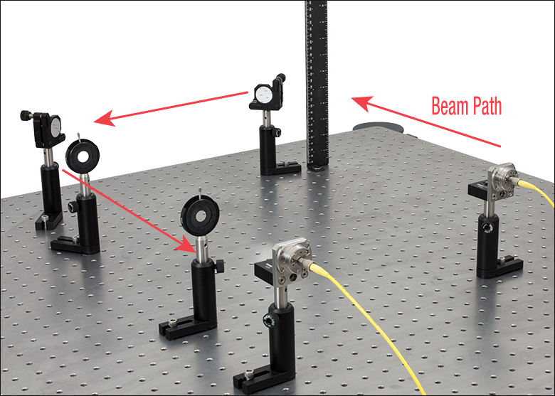
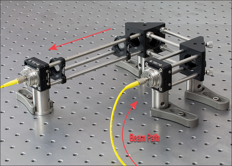
Common Alignment Setups
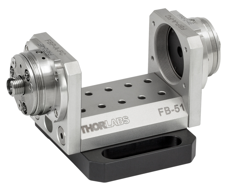
There are multiple ways to configure an alignment setup. A common method of alignment is to use two mirrors and two irises, as seen in the left and center images below. Alternatively, a FiberBench, seen in the image below and to the right, can provide a quick and compact way to utilize two FiberPorts in your system.
Click to Enlarge
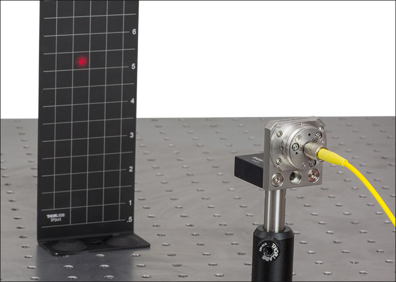
A FiberBench provides a stable and quick way to integrate multiple FiberPorts into your system. A single-axis FB-51W FiberBench is seen above.
 Click for Details
A post-mounted alignment setup can be made with components that are common in many labs. Note: the previous generation BHM2 ruler is used in this setup.
 Click for Details
A cage system can simplify the alignment process by fixing all components along a common optical axis.
- Ensure that the center of your mirrors, irises, and FiberPort are centered on the same optical axis. Our cage system and FiberBench systems can simplify this step.
- If using an FC/PC or FC/APC connector, make sure that the key on your fiber connector is aligned with your FiberPort. If using polarization-maintaining fiber, the bulkhead of the FiberPort can be rotated to match the fiber's polarization. This should be done as early as possible in the alignment process. Please see the Operation tab for more information.
- Align the mirror closest to the beam source with the iris it is closest to by placing a laser viewing card or aligment target directly after that iris. Partially close the iris until the beam spot begins to disappear. If one side of the beam is clipped first, adjust the mirror so that the beam is more centered with the iris. Align the other mirror and iris with each other in the same way.
- Repeat steps 2 and 3 until both mirrors and irises are aligned.
Collimating with a FiberPort
Step 1
Start with a pre-aligned FiberPort, as discussed in the Pre-alignment section above.Step 2
Check for collimation by measuring the beam diameter close to and downstream from your source1.
Step 3
Uniformly turn the Zθ adjusters clockwise by aligning your ball driver with the adjusters so that the number of rotations can be counted. Each adjuster must receive the same number of rotations to ensure the lens remains orthogonal to the beam axis and beam quality is preserved2.
Step 4
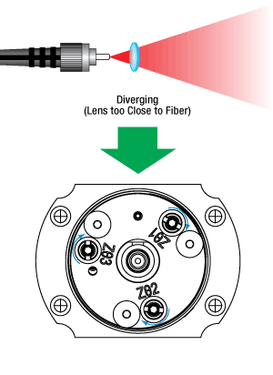
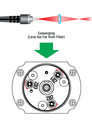
After each set of adjustments, measure the beam diameter from the same locations in step 2. If the beam is converging, the lens is too far away from the fiber. If the beam is diverging, the lens is too close to the fiber. Adjust the Zθ adjusters according to the diagram to the right. Once the downstream beam diameter is approximately equal to the beam's diameter near the source, your beam is collimated.
Common Issues
- I cannot tell if my beam is collimated: The further from the source you measure, the easier it is to view the difference in beam diameter.
- Even though my X and Y position look correct, there is still an offset in the beam: Please ensure that care has been taken in pre-alignment. See the Pre-alignment section for more information.
Coupling into Fiber via FiberPort
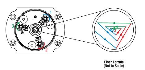 When turning each adjuster by equal increments, the beam traces a triangular pattern of changing width. The maximum power is seen not at either end of each turn's travel range, but in the middle when the beam is closest to the fiber's core. The beam's path is shown with point of view of the fiber that is being coupled into.
 Principle
While translation in the X- and Y- directions can be directly made by using their respective adjusters, translation in the Z-direction must be made by incremental tip/tilt adjustments using the three Zθ adjusters. As a result, the beam's path as the adjusters are turned may not be intuitive. Equal rotations to each of the Zθ adjusters result in the beam spot tracing a triangle around the core of the fiber, as illustrated to the right. Once some measureable output exists, a typical alignment strategy would consist of turning each screw to maximize the output, and then continuing to turn slightly beyond maximum (about 95% of your local max). This must be done for each adjuster, and in the same order for each trio of adjustments1. This method prevents the power from being stuck at a local maximum. The maximum seen in each passing will continue to increase until the lens-to-fiber spacing is optimized (spot size is minimized), and a global maximum is reached. This strategy has the effect of translating the beam in a triangle of decreasing width with each set of adjustments.
Note that the typical maximum coupling efficiency is highly dependent on the system configuration and setup. Most configurations will achieve efficiencies between 60% and 80%. This efficiency can be improved upon by ensuring precise alignment with all system components, and verifying the compatibility of all components. Efficiencies below 50% may indicate significant component mismatch or alignment error.
Step 3
Choose an sequence to make your adjustments, and keep to that sequence1 . Turn each Zθ adjuster clockwise to maximize the output, then continue to turn slightly beyond local maxima (to ~95% of your local maximum). If turning an adjuster clockwise decreases output, skip that adjuster for that round of adjustments and repeat. Once the local maxima values begin to decrease, reverse the direction, and turn each adjuster to maximize the output, and not beyond.
Step 2
Insert a multimode (MM) fiber that is compatible with your system2 into the FiberPort and a power meter. Maximize the X and Y alignment by observing where the intensity peaks for each position. Once a maximum is reach, these adjusters should not be changed unless SM fiber is later used.
Step 1
Start with a pre-aligned FiberPort, as discussed in the Pre-alignment section above.
Step 6 (Optional)
If desired, the adjusters can be locked via the locking collars by the use of the included SPW403 spanner wrench. Additionally, the lens cell can be locked in place by installing the included 0-80 screw located in the 4 o'clock position of the front face of the FiberPort.
Single Mode Fiber Only
Step 5
Repeat Step 3. The adjustments will need to be smaller, as the system will be more sensitive. If adjustment of all screws in either direction lowers the output, the beam spot may be centered on the fiber core, but be improperly focused. Turn each adjuster a small amount (1/16th turn) in the same direction, then maximize each Zθ adjuster. If the new maximum is lower than the previous, turn each Zθ adjuster a small amount in the other direction and maximize. Repeat until absolute maximum is found.
Step 4
If coupling into a SM fiber, exchange the MM fiber with a SM fiber. The intensity measured by the power meter will likely drop significantly.
Common Issues
- I do not know what order to turn the adjusters: For instance, if you chose to adjust Zθ3, then Zθ1, then Zθ2, ensure you continue in this order for each set of adjustments.
- I do not know what fiber is most compatible with my system: Please see the Selection Guide tab for more information
Theoretical Approximation of the Divergence Angle
The full-angle beam divergence listed in the specifications tables is the theoretically-calculated value associated with the fiber collimator. This divergence angle is easy to approximate theoretically using the formula below as long as the light emerging from the fiber has a Gaussian intensity profile. Consequently, the formula works well for single mode fibers, but it will underestimate the divergence angle for multimode (MM) fibers since the light emerging from an MM fiber has a non-Gaussian intensity profile.
The Full Divergence Angle (in degrees) is given by
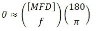
where MFD is the mode field diameter and f is the focal length of the collimator. (Note: MFD and f must have the same units in this equation).
Example:
When the PAF2-A4A collimator is used with a single mode fiber such as the 460HP such that MFD = 3.5 µm and f ≈ 4.0 mm, the divergence angle is
θ ≈ (0.0035 mm / 4.0 mm)*(180/3.1416) ≈ 0.050° or 0.875 mrad.
Theoretical Approximation of the Output Beam Diameter
The output beam diameter can be approximated from
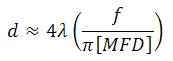
where λ is the wavelength of light being used, MFD is the mode field diameter, and f is the focal length of the collimator.
Example:
When the PAF2-A4A collimator (f = 4.0 mm) is used with the 460HP fiber (MFD = 3.5 µm) and 450 nm light, the output beam diameter is
(4)(450 nm)[4.0 mm / (π · 3.5 µm)] = 0.65 mm
Theoretical Approximation of the Maximum Waist Distance
The maximum waist distance, which is the furthest distance from the lens the waist can be located in order to maintain collimation, may be approximated by:
where f is the focal length of the collimator, λ is the wavelength of light used, and MFD is the mode field diameter.
Example:
When the PAF2-A4A collimator is used with a single mode fiber such as the 460HP such that MFD = 3.5 µm, f ≈ 4.0 mm, and λ = 450 nm, then the maximum waist distance is
4 mm + (2 (4 mm)2 (450 nm) / (3.1416) (3.5 µm)2) = 378 mm.
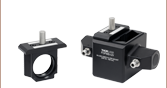
| FiberPort Cage Mount | FiberPort Post Mount | ||
|---|---|---|---|
 Click to Enlarge Click to Enlarge |
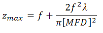
The CP08FP FiberPort Cage Mount is designed to center a FiberPort inside a 30 mm cage system. The CP08FP secures to the four ER rods of a 30 mm cage assembly. Four included 2-56 stainless steel socket head screws secure a FiberPort to the adapter. The CP08FP has internal SM1 (1.035"-40) threading, enabling it to be used with our extensive line of Ø1" lens tubes, and also 8-32 or M4 taps for post mounting. | 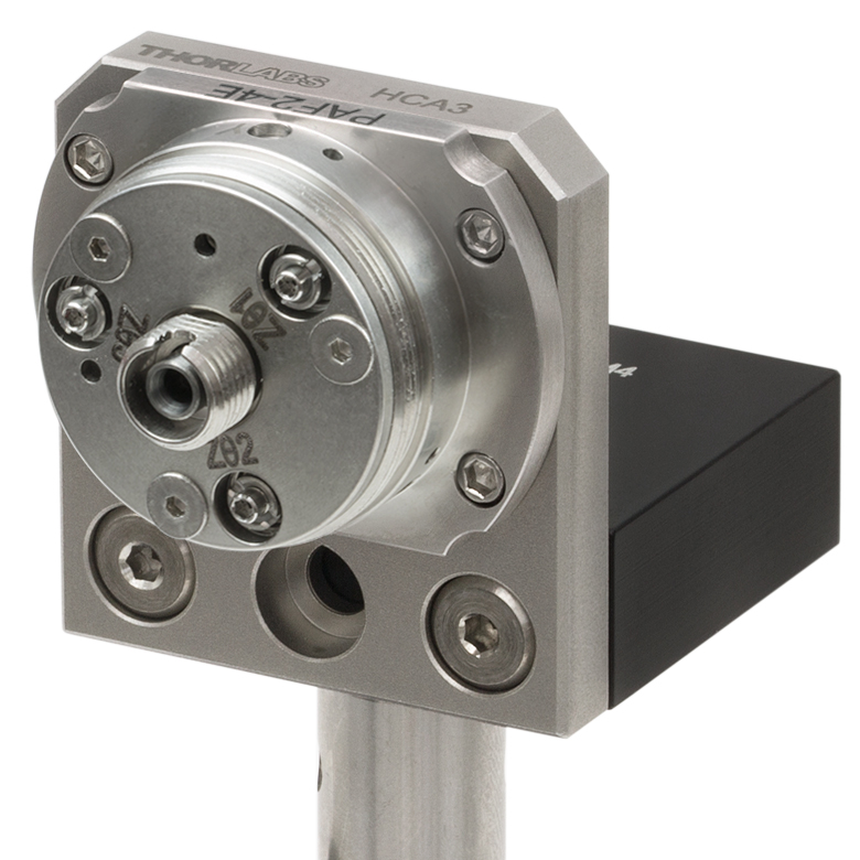 Click to Enlarge |
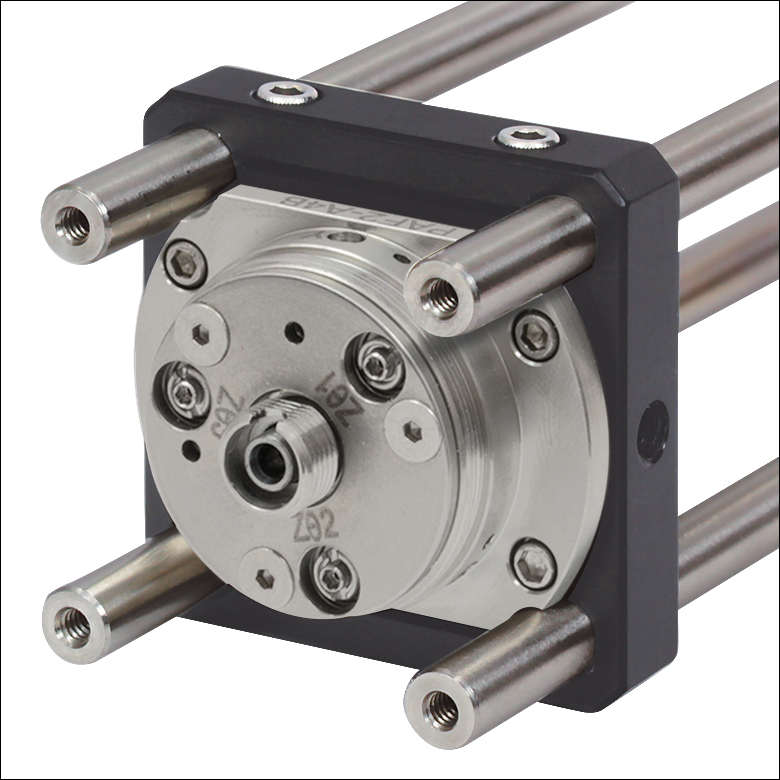
The HCP Post Mounting Bracket has four 2-56 threaded holes for securing a FiberPort to the front plate. The bottom of the L-bracket can be easily attached to an optical table, breadboard, or post, since it has 8-32- and M4-threaded holes, as well as a 1/4" (M6) counterbored hole. |
| FiberPort Standard HeNe Adapter | FiberPort 5/8"-32 Threaded HeNe Adapter | ||
 Click to Enlarge |
The HCL HeNe to FiberPort Adapter attaches a FiberPort directly to the front of a HeNe laser with an industry-standard four-bolt pattern. For additional mounting options, the HCL features internal C-Mount (1.000"-32) threading, which is utilized on some lasers. All mounting screws are included. See Section 6.3 of the FiberPort manual (available as a PDF here) for details. | 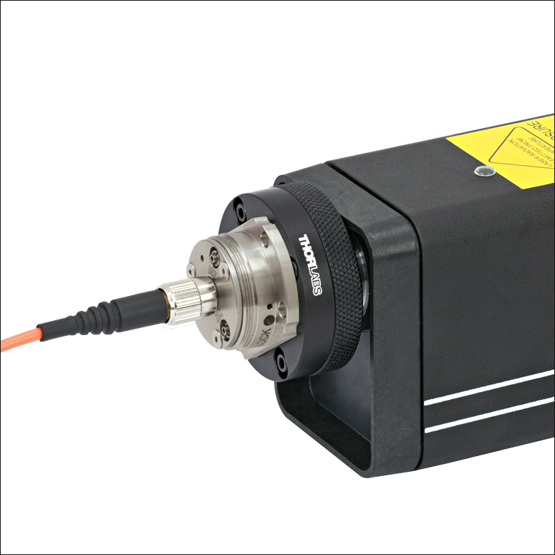 Click to Enlarge |
The HCL2 Self-Contained HeNe to FiberPort Adapter, which features external 5/8"-32 threading, allows a FiberPort coupler to be attached directly to the threaded aperture of our self-contained HeNe lasers or any other 5/8"-32 tapped hole. A slip-plate design allows the position of the FiberPort to be shifted and locked to maximize coupling efficiency. FiberPort mounting screws are included. See Section 6.3 of the FiberPort manual (available as a PDF here) for details. |
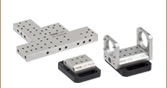
| FiberPort and FiberBench | |||
 Click to Enlarge |
Thorlabs' fiber-to-fiber U-Benches consist of a FiberBench base combined with two FiberPorts. The U-Benches allow for easy access to the optical beam and are ideal for fiber-to-fiber applications that incorporate multiple components and require the utmost in stability. Thorlabs offers a complete line of optical subassemblies that can be placed into the beam path. We also offer our FiberBenches bundled with two compatible FiberPorts. | ||

Insights into Optical Fiber
Scroll down to read about:
- When does NA provide a good estimate of the fiber's acceptance angle?
- Why is MFD an important coupling parameter for single mode fibers?
- Does NA provide a good estimate of beam divergence from a single mode fiber?
Click here for more insights into lab practices and equipment.
When does NA provide a good estimate of the fiber's acceptance angle?

Click to Enlarge
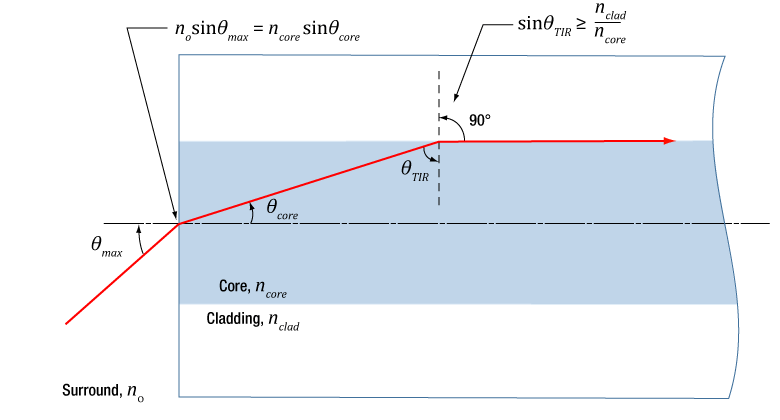
Figure 1: Rays incident at angles ≤θmax will be captured by the cores of multimode fiber, since these rays experience total internal reflection at the interface between core and cladding.
Click to Enlarge
Figure 2: The behavior of the ray at the boundary between the core and cladding, which depends on their refractive indices, determines whether the ray incident on the end face is coupled into the core. The equation for NA can be found using geometry and the two equations noted at the top of this figure.
Numerical aperture (NA) provides a good estimate of the maximum acceptance angle for most multimode fibers, as shown in Figure 1. This relationship should not be used for single mode fibers.
NA and Acceptance Angle
Incident light is modeled as rays to obtain the relationship between NA and the maximum acceptance angle (θmax ), which describes the fiber's ability to gather light from off-axis sources. The equation at the top of Figure 1 can be used to determine whether rays traced from different light sources will be coupled into the fiber's core.
Rays with an angle of incidence ≤θmax are totally internally reflected (TIR) at the boundary between the fiber's core and cladding. As these rays propagate down the fiber, they remain trapped in the core.
Rays with angles of incidence larger than θmax refract at the interface between core and cladding, and this light is eventually lost from the fiber.
Geometry Defines the Relationship
The relationship among NA, θmax , and the refractive indices of the core and cladding, ncore and nclad , respectively, can be found using the geometry diagrammed in Figure 2. This geometry illustrates the most extreme conditions under which TIR will occur at the boundary between the core and cladding.
The equations at the top of Figure 2 are expressions of Snell's law and describe the rays' behavior at both interfaces. Note that the simplification sin(90°) = 1 has been used. Only the indices of the core and cladding limit the value of θmax .
Angles of Incidence and Fiber Modes
When the angle of incidence is ≤θmax , the incident light ray is coupled into one of the multimode fiber's guided modes. Generally speaking, the lower the angle of incidence, the lower the order of the excited fiber mode. Lower-order modes concentrate most of their intensity near the center of the core. The lowest order mode is excited by rays incident normally on the end face.
Single Mode Fibers are Different
In the case of single mode fibers, the ray model in Figure 2 is not useful, and the calculated NA (acceptance angle) does not equal the maximum angle of incidence or describe the fiber's light gathering ability.
Single mode fibers have only one guided mode, the lowest order mode, which is excited by rays with 0° angles of incidence. However, calculating the NA results in a nonzero value. The ray model also does not accurately predict the divergence angles of the light beams successfully coupled into and emitted from single mode fibers. The beam divergence occurs due to diffraction effects, which are not taken into account by the ray model but can be described using the wave optics model. The Gaussian beam propagation model can be used to calculate beam divergence with high accuracy.
Date of Last Edit: Jan. 20, 2020
Why is MFD an important coupling parameter for single mode fibers?
Click to Enlarge
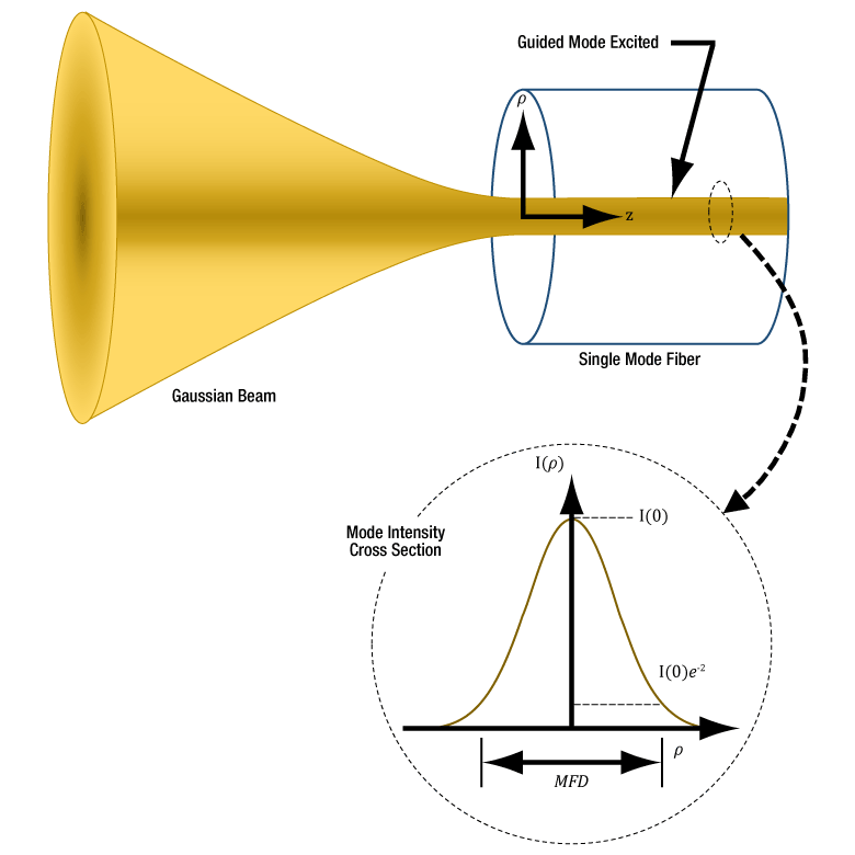
Figure 3 For maximum coupling efficiency into single mode fibers, the light should be an on-axis Gaussian beam with its waist located at the fiber's end face, and the waist diameter should equal the MFD. The beam output by the fiber also resembles a Gaussian with these characteristics. In the case of single mode fibers, the ray optics model and NA are inadequate for determining coupling conditions. The mode intensity (I ) profile across the radius ( ρ ) is illustrated.
As light propagates down a single mode fiber, the beam maintains a cross sectional profile that is nearly Gaussian in shape. The mode field diameter (MFD) describes the width of this intensity profile. The better an incident beam matches this intensity profile, the larger the fraction of light coupled into the fiber. An incident Gaussian beam with a beam waist equal to the MFD can achieve particularly high coupling efficiency.
Using the MFD as the beam waist in the Gaussian beam propagation model can provide highly accurate incident beam parameters, as well as the output beam's divergence.
Determining Coupling Requirements
A benefit of optical fibers is that light carried by the fibers' guided mode(s) does not spread out radially and is minimally attenuated as it propagates. Coupling light into one of a fiber's guided modes requires matching the characteristics of the incident light to those of the mode. Light that is not coupled into a guided mode radiates out of the fiber and is lost. This light is said to leak out of the fiber.
Single mode fibers have one guided mode, and wave optics analysis reveals the mode to be described by a Bessel function. The amplitude profiles of Gaussian and Bessel functions closely resemble one another, which is convenient since using a Gaussian function as a substitute simplifies the modeling the fiber's mode while providing accurate results (Kowalevicz).
Figure 3 illustrates the single mode fiber's mode intensity cross section, which the incident light must match in order to couple into the guided mode. The intensity (I ) profile is a near-Gaussian function of radial distance ( ρ ). The MFD, which is constant along the fiber's length, is the width measured at an intensity equal to the product of e-2 and the peak intensity. The MFD encloses ~86% of the beam's power.
Since lasers emitting only the lowest-order transverse mode provide Gaussian beams, this laser light can be efficiently coupled into single mode fibers.
Coupling Light into the Single Mode Fiber
To efficiently couple light into the core of a single-mode fiber, the waist of the incident Gaussian beam should be located at the fiber's end face. The intensity profile of the beam's waist should overlap and match the characteristics of the mode intensity cross section. The required incident beam parameters can be calculated using the fiber's MFD with the Gaussian beam propagation model.
The coupling efficiency will be reduced if the beam waist is a different diameter than the MFD, the cross-sectional profile of the beam is distorted or shifted with respect to the modal spot at the end face, and / or if the light is not directed along the fiber's axis.
References
Kowalevicz A and Bucholtz F, "Beam Divergence from an SMF-28 Optical Fiber (NRL/MR/5650--06-8996)." Naval Research Laboratory, 2006.
Date of Last Edit: Feb. 28, 2020
Why is MFD an important coupling parameter for single mode fibers?
Significant error can result when the numerical aperture (NA) is used to estimate the cone of light emitted from, or that can be coupled into, a single mode fiber. A better estimate is obtained using the Gaussian beam propagation model to calculate the divergence angle. This model allows the divergence angle to be calculated for whatever beam spot size best suits the application.
Since the mode field diameter (MFD) specified for single mode optical fibers encloses ~86% of the beam power, this definition of spot size is often appropriate when collimating light from and focusing light into a single mode fiber. In this case, to a first approximation and when measured in the far field,
 , , |
(1) |
is the divergence or acceptance angle (θSM ), in radians. This is half the full angular extent of the beam, it is wavelength  )
)
| Rayleigh Range: | ||
 |
||
| Beam Radius at Distance z: | ||
 |
||
|
Figure 4: These curves illustrate the consequence of using NA to calculate the divergence (θSM ) of light output from a single mode fiber. Significant error in beam spot diameter can be avoided by using the Gaussian beam propagation model. This plot models a beam from SM980-5.8-125. The values used for NA and MFD were 0.13 and 6.4 µm, respectively. The operating wavelength was 980 nm, and the Rayleigh range was 32.8 µm. |
||
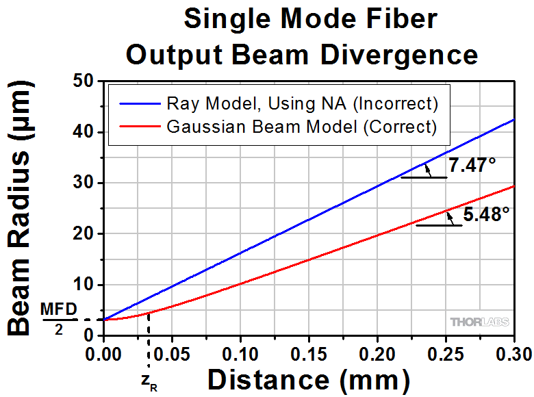
Gaussian Beam Approach
Although a diverging cone of light is emitted from the end face of a single mode optical fiber, this light does not behave as multiple rays travelling at different angles to the fiber's axis.
Instead, this light resembles and can be modeled as a single Gaussian beam. The emitted light propagates similarly to a Gaussian beam since the guided fiber mode that carried the light has near-Gaussian characteristics.
The divergence angle of a Gaussian beam can differ substantially from the angle calculated by assuming the light behaves as rays. Using the ray model, the divergence angle would equal sin-1(NA). However, the relationship between NA and divergence angle is only valid for highly multimode fibers.
Figure 4 illustrates that using the NA to estimate the divergence angle can result in significant error. In this case, the divergence angle was needed for a point on the circle enclosing 86% of the beam's optical power. The intensity of a point on this circle is a factor of 1/e2 lower than the peak intensity.
The equations to the right of the plot in Figure 4 were used to accurately model the divergence of the beam emitted from the single mode fiber's end face. The values used to complete the calculations, including the fiber's MFD, NA, and operating wavelength are given in the figure's caption. This rate of beam divergence assumes a beam size defined by the 1/e2 radius, is nonlinear for distances z < zR, and is approximately linear in the far field (z >> zR).
The angles noted on the plot were calculated from each curve's respective slope. When the far field approximation given by Equation (1) is used, the calculated divergence angle is 0.098 radians (5.61°).
References
Kowalevicz A and Bucholtz F, "Beam Divergence from an SMF-28 Optical Fiber (NRL/MR/5650--06-8996)." Naval Research Laboratory, 2006.
Date of Last Edit: Feb. 28, 2020
Content improved by our readers!
| Posted Comments: | |
user
(posted 2024-08-12 09:31:18.51) Dear Thorlabs, in the "Calculations"-tab you gave a formula describing the maximum waist distance, at which a beam can still be considered collimated. Can you give me some context, where this formula is coming from (How you derived it, what literature it's coming from, or most importantly, what assumptions did you make for "maximum" wais distance.)? Thank you in adwance. George Dubelaar
(posted 2024-07-04 14:59:10.99) Dear Thorlabs,
I want to try a fiberport (e.g. PAF2P-15A) to collimate the output of a PM-S405-XP fiber coupled to a 520nm laser.
Please advise the best type of fiberport for this set-up, and let me know if it is possible that we can receive one of those to evaluate before we decide to use them in our instruments. Thanks for your help,
George Dubelaar
CytoBuoy bv optics dept. jdelia
(posted 2024-07-09 02:16:18.0) Thank you for contacting Thorlabs. I have reached out to you directly via email to discuss your application. Ideally, you would want to make sure the connector type, the NA, and the AR coating are appropriate for your input fiber and laser source. Sebastian Slaman
(posted 2024-06-17 16:48:24.803) What is the maximum temperature these collimators are rated for? cdolbashian
(posted 2024-06-28 11:51:01.0) Thank you for reaching out to us with this inquiry. The epoxies inside will begin to fail around 80-90°C. With higher temp epoxies the device will become unusable at ~120°C as this is the Curie Temp of the magnetic lens cell within the device. above this temp the lens will not be able to maintain a set position. Viktor Dubec
(posted 2024-04-08 15:14:50.677) Hello, what is the tolerance of the opening where the fiber is inserted? I have got following task: I want to use 50um core multi-mode fiber because my laser spot in the focus is around 40-50um. In can do the alignment easily and I get over 80% efficiency. But after I remove the fiber and insert it back, the alignment is lost. Is there any solution how to make this process repeatable without new alignment? Or is it impossible due to small mechanical dimensions and tolerances of the coupler and fiber? Thank you! ksosnowski
(posted 2024-05-09 04:45:31.0) Hello Viktor, thanks for reaching out to Thorlabs. With the worst case tolerance of our SMA Fiberport and standard SMA905 connectors there could be up to 20um clearance in the bore of the bulkhead. Depending on the exact fiber and connector used, the concentricity there may also effect coupling on repeated insertions. Connectors with an orientation key like FC/PC may help repeatability of the insertion as well. I have reached out directly to discuss this application in further detail. Francois Parnet
(posted 2024-01-30 10:14:40.54) Hello, I can't find the distance between the FC/APC end tip of the pigtail inserted into the Fiberport and the lens. Only the length L between the FC/APC connector and the metal package is given. I need to know what is the excursion of +/-1mm for this PAF2A-18C component.
Thank you cdolbashian
(posted 2024-02-02 09:50:30.0) Thank you for reaching out to us with this inquiry. Looking at the lens used within this component, it seems that while the focal length is ~18.4mm, the working distance is closer to 17mm. With this fact, we design the fiberport such that the WD of the lens is coincident with the tip of the fiber when the Z translation is at its zero position. In this sense, this will allow +/-1mm travel to optimize collimation/coupling. I have contacted you directly to discuss this. Craig Prater
(posted 2023-11-22 13:56:34.933) So far, I am extremely disappointed with this product. I find the FiberPort devices to be extremely difficult to use and not stable over time. The most frustrating aspect is that I am seeing uncontrolled shifts in the relative position of the coupling optics to the fiber that has on at least five occasions has led to complete or almost complete loss of coupling of light into the fiber. On several occasions, I have been very close to maximizing the light coupling when there was a sudden loss of coupling even when I was nowhere close to the unit. After the loss of coupling, I find the new optimal coupling position and focus way off of the previous location, for example up to half a turn of the Z-theta adjustment screws. I have seen this behavior with two different FiperPort couplers I bought. (I am also confident that the problem is associated with the FiberPort couplers and not some other component in my optical system because I am coupling the same laser beam via a beam splitter into the two different FiberPorts and I will see one or the other coupler suddenly lose coupling, while the other is still coupling ok. So it is not any upstream optics. I also find the units very difficult to use because the heads of the adjustment screws are so small, it is very difficult to get an Allen wrench into the the adjusters, especially the z-theta two adjuster which is below the other two adjuster where it is difficult to see and difficult to access. I also find that the XY adjustments are not very smooth with lots of backlash and some cross-coupling. I bought these units to test for possible inclusion in an OEM product, but with my current experience, I can't imagine including these couplers in a product.
At this stage I would like some guidance about other options that will be more robust for single mode fiber coupling. jpolaris
(posted 2023-12-04 05:10:55.0) Thank you for contacting Thorlabs. Your feedback is valued, and I am sorry that you have been having a difficult time with our FiberPorts. I have reached out to you directly to discuss your setup and to explore possible reasons for the issues you are experiencing. Our FiberPorts are designed with stability (mechanical and thermal), repeatability, and functionality in mind. For this reason, I find your description of the issue surprising -- especially the part about you losing coupling while nowhere near the FiberPort. Single-mode coupling is notoriously tricky, so I have reached out to you to try to identify if the issues you are experiencing are procedural (alignment technique) or mechanical (faulty FiberPort) in nature. We provide a FiberPort alignment procedure located at the following link. Following this procedure helps ensure that you do not find yourself at local unstable coupling efficiency maxima. As you home in on the "true maximum" coupling efficiency, you will pass through these local maxima. When this happens, it is completely normal for the coupling efficiency to temporarily rise to a peak, then fall off dramatically. This process will continue until you've found the ideal adjustor positions. The alignment procedure can be found here: https://www.thorlabs.com/newgrouppage9.cfm?objectgroup_id=2940&tabname=Alignment_Procedure Yuheng Huyan
(posted 2023-11-13 17:14:02.3) Dear Thorlabs,
Does the coupler performs the same for high power laser? Is the coupling efficiency power dependent?
Best,
YH cdolbashian
(posted 2023-11-29 02:01:17.0) Thank you for reaching out to us with this inquiry. The effect you could potentially see would be thermal lensing, when using a high power laser and considering the coupling efficiency. Alternatively, you could potentially damage the lens inside or strip the anti reflective coating. I have contacted you directly to inquire regarding your optical setup, laser parameters, and eventual experimental requirements. user
(posted 2023-07-07 14:49:47.403) Hello, We recently purchased a PAF2S-2B. I would like to access to a Zemax file of the aspheric lens, such as to modelize further the beam.
Is it possible to get one by email ?
Thanks. cdolbashian
(posted 2023-07-13 01:58:35.0) Thank you for reaching out to us with this inquiry. Thankfully the lens inside this FiberPort is a stock asphere: 355151-B. The Zemax files can be found here: https://www.thorlabs.com/thorproduct.cfm?partnumber=355151-B ChangYi Lin
(posted 2023-06-05 19:31:03.607) Dear Thorlabs, I would like to ask some questions about my multimode fiber laser. I need to use a 915nm CW fiber laser. Its NA is 0.22, core size is 200um, and connector is SMA905. Is it suitable with PAF2S-2B? What is the coupling efficiency? How to estimate the beam divergence angle after passing through PAF2S-2B? core size/focus = 200um/2mm=0.1rad? Thank you. cdolbashian
(posted 2023-06-12 01:39:25.0) Thank you for reaching out to us with this inquiry. In order to understand your application and intent, I have contacted you directly. For future technical/usage inquiries, please contact techsupport@thorlabs.com. Tobias Kuhnke
(posted 2023-03-13 13:39:49.083) Dear Thorlabs,
I am using multiple PAF2A-15C Ports for coupling 1310 nm SLED radiation in between single mode fibres with different base plates yielding 5 cm and 10 cm distance between the ports.
During the alignment process we've found out that the coupling efficiency is highly dependent on an optimal z-value between the ports for higher working distances. Sub-optimal z-values will drag down coupling efficiency when working with higher working distance.
One finds optimal z-values by subsequently increasing the working distance and adjusting z-theta for z-value. When z is optimal, a small change in x- and y-axis value will drop coupling effiency sharply. jgreschler
(posted 2023-03-13 02:40:02.0) Thank you for your valuable feedback regarding fiber coupling with our FiberPorts. I have reached out to you directly to suggest some tips and tricks to make the process of fiber coupling a little easier! We also have a video demonstration of one of our engineers bringing their efficiency to 80% here which is great to follow along with https://youtu.be/0HejWlZj0LU. zhang Aaron
(posted 2022-09-25 01:26:14.297) FiberPort 产品型号为PAF2-5B 中近光纤连接器端的透镜破损,请问有替换元件吗 cdolbashian
(posted 2022-10-04 04:15:27.0) Thank you for reaching out to us. If you have a broken component in one of your products, please reach out to Techsupport@thorlabs.com to troubleshoot and identify the issue. I have reached out to you in this situation to troubleshoot your device. YU DONG
(posted 2022-08-31 09:05:01.813) What is the coupling efficiency of the coupler and the laser emission wavelength is 532nm. Ilan Sher
(posted 2022-08-14 23:20:51.903) Hello, I trying to couple laser to the PAF2A-11B collimator sitting on the HCP L-Bracket Mount to PM fiber. I noticed that the colimator is tilted even with all Ztheta screws is losen so the tiltplate supposed to be straight. How can i fix that tilt to make the coupling efficient? Thanks jgreschler
(posted 2022-08-25 10:26:15.0) Thank you for reaching out to Thorlabs. I have reached out to you directly to discuss troubleshooting, and set up a return for repair on your unit of PAF2A-11B. M Eskandari
(posted 2021-12-28 03:01:59.553) Hello,
I have bought a free space single-photon detector from MPD (http://www.micro-photon-devices.com/Products), but now I'm going to modify it to a fiber-coupled version.
I think by attaching PAF2P-15B and a simple mechanical adapter on the detector, I can direct the 810 nm light on the 50 um effective area of the detector.
Is this part suitable?
Regards jgreschler
(posted 2022-01-04 11:22:46.0) Thank you for reaching out to Thorlabs. I have reached out to you directly to discuss your application further. Yong Guk Kang
(posted 2021-12-07 23:47:26.143) Hello, I am trying to catch and launch the free space SLD beam to the single-mode fiber. (780)
the bandwidth of free space SLD beam is around 800~850nm, and its collimated beam diameter is 2.5mm.
for best efficiency, which one should I use? PAF2A-A10B (output dia. 2.16 mm)or PAF2A-A15B(output dia3.25mm) ?
regards, jgreschler
(posted 2021-12-14 09:07:35.0) Thank you for reaching out to Thorlabs. The parameter that will dictate whether your input beam clips the lens is actually the clear aperture (CA) of the system. In both items the CA spec is 4.5mm, which is more than enough for a 2.5mm input beam. Given your fiber's NA and MFD specs the PAF2A-A10B is the correct choice for this application, which is in agreement with the FiberPort calculator in the Selection Guide tab of this product page. Paul D
(posted 2021-11-26 09:08:25.307) Hi,
We are currently using the PAF2-2A and it's a great product. Do you plan to release an achromatic FiberPort with a 2-mm focal length? The shortest focal length of your achromatic FiberPort (4mm) is too large for our optical system.
Thanks YLohia
(posted 2021-12-10 02:14:45.0) Hello, thank you for your feedback. Unfortunately, we don't have any plans of releasing shorter focal length achromatic Fiberports in the near-future. That being said, we have noted your request and hope to look into a solution for this. Bethany Foxon
(posted 2021-09-08 04:34:44.083) Hello, do you have the ZMX file for the the PAF2-5A? Thank you YLohia
(posted 2021-09-08 12:01:15.0) Hello, we don't offer Zemax files for the entire FiberPort assembly but we are able to offer Zemax files for the component lenses used in the FiberPorts in most cases. The PAF2-5A uses the A390-A lens and its Zemax file can be found here: https://www.thorlabs.com/thorproduct.cfm?partnumber=A390-A. jia gao
(posted 2021-06-21 10:35:12.59) We used the fiber coupler to align four lasers with different wavelength. But adjusting the knobs on the mirrors and x y a on coupler. We successfully adjusted the efficiency for all four lasers to 50%. However, when we came to lab another day, the efficiency dropped dramatically to micro again… we wonder if it is due to the fiber coupler too sensitive? Should we lock the x y after setting. YLohia
(posted 2021-06-28 10:18:24.0) Thank you for contacting Thorlabs. Please check the long term / temperature related drifts of your collimated beam going into the PAF. In the event of a positional drift of the beam, the coupling efficiency can drop significantly. It is recommended to lock the X-Y adjusters once alignment has been completed. Kais Almarzouk
(posted 2021-05-20 18:09:45.25) Do you have a Zemax copy of this item (PAF-X-18-B)? If you do can you email it to me. Thank you. YLohia
(posted 2021-05-21 10:54:50.0) Hello, I have reached out to you directly regarding this. Jaemin Song
(posted 2021-05-19 00:36:21.53) Hi,
I am looking for a collimator for the range of wavelengths between 400nm and 900nm.
So, I found PAF2S-A7A as one of my collimator systems.
However, I am a little confused with the possible transmission and collimating range.
The wavelength range of the AR coating is 400-700 nm, while the transmission range of materials(N-BAF10 / N-SF6HT) is starting from about 600 nm.
Then, this collimator only be used within 600 ~ 700 bm wavelength. Am I right?
please, check the AR coating and lens material of PAF2S-A7A.
Thank you. YLohia
(posted 2021-05-19 01:34:25.0) Hello, thank you for contacting Thorlabs. The PAF2S-A7A can still be used for its specified wavelength range of 400 - 700 nm, but the internal transmission in the 400-600 nm range will be roughly 80-95%. If the loss due to transmission isn't too high for your application, the PAF2S-A7A can still be used. Alex C
(posted 2021-05-11 11:32:45.257) I’m currently working on a project using 2 Thor labs FIberPorts that seem to be discontinued, and one of them I can not find the serial number on your website is it possible to get the specifications for these? One the serial PAF-X-7-780 and the other is PAF-X-7-B. The -780 has a longer connection port. Any information/specifications would be greatly appreciated. YLohia
(posted 2021-05-12 11:03:30.0) Thank you for contacting Thorlabs. The specs for PAF-X-7-B can be found here (https://www.thorlabs.com/catalogpages/obsolete/2018/PAF-X-7-B.pdf) or here (https://www.thorlabs.com/_sd.cfm?fileName=16164-D02.pdf&partNumber=PAF-X-7-B). We don't have any item number PAF-X-7-780 in our system. Vijay C
(posted 2021-03-22 22:31:27.1) Hi,
What is the difference between the item PAF2P-18C and PAF2A-18C. Since both looks same, I am confused to choose the right product for my application. YLohia
(posted 2021-03-23 10:24:58.0) Hello, the PAF2P-18C has FC/PC connectors while the PAF2A-18C has FC/APC connectors. Jens Flügge
(posted 2021-03-09 05:28:03.527) Ladies and Gentlemen,
are the FiberPort Collimators also avalable for
vacuum (10^-4 mBar range) ?
Kind Regards YLohia
(posted 2021-03-09 11:38:19.0) Thank you for contacting Thorlabs. Unfortunately, we cannot guarantee vacuum performance of these due to lack of test data. While we don't foresee a catastrophic event, outgassing is expected to cause problems. The grease used is Krytox LVP, which is vacuum compatible. Most components are 303 stainless steel. The only plastic is PTFE. The lenses are attached with F113 and Armstrong A-12, which may outgas significantly, but only small amounts are used. If you would like to attempt using the FiberPort in vacuum, we would suggest removing the aluminum tilt plate cover and the adhesive that attaches it. This would be entirely at your risk, as we cannot guarantee the performance for this application. Greg Whitfield
(posted 2021-03-03 11:23:29.077) I am interested in using the PAF2 fiber alignment positioner without a lens. Is this possible? asundararaj
(posted 2021-03-03 03:48:31.0) Hello, thank you for contacting Thorlabs. Quotes for custom items can be requested by clicking the red "Request Quote" button above or emailing your local Thorlabs Tech Support team. We have reached out to you directly to discuss the possibility of offering this custom. user
(posted 2020-08-12 18:38:51.23) I wanted to have a solution to couple the collimated light coming from a broadband source (like the SLS201L with the SLS201C collimator) into a SM fiber with an MFD of ~10um and NA=0.23. I understand that it would be challenging to couple all the wavelengths into a SM fiber. The best possible solution that I could see was with the achromatic fiberports (even if I will not be able to sample the entore beam size of the SLS201L source). What would you suggest? nbayconich
(posted 2020-08-13 03:40:33.0) Thank you for contacting Thorlabs. It is not recommended to attempt to couple light from a broadband light source such as the SLS201L into any type of single mode fiber. With or without a fiberport system, the coupling efficiency will be extremely low and not suitable for most applications.
I will reach out to you directly to discuss your application. chi xu
(posted 2020-03-05 15:01:50.03) What is the max laser power this fiber-port/coating can handle?@1550 nm nbayconich
(posted 2020-03-05 03:40:35.0) Thank you for contacting Thorlabs. We have not yet tested the pulsed or CW damage threshold for these particular fiberport lenses however, in most cases the maximum power that can be used will be limited to the fiber connector's epoxy. I will reach out to you directly to discuss your application. abhishek akn
(posted 2019-11-26 08:56:28.963) Hello, Please let me know the damage threshold for PAF2A-18B fibreport collimator. I will be using it with 100mW FC/APC laser module with pulse repeatation 10MHz, 10ns pulse width. nbayconich
(posted 2019-11-27 10:00:02.0) Thank you for contacting Thorlabs. We have not yet tested the pulsed damage threshold for these particular lenses however given the low average power and low pulse energy density of your source, we would not expect your source to damage these lenses used in this fiberport collimator. user
(posted 2019-08-09 07:46:04.487) Hello. I need to lock the X Y position of the lens in the PAF2A-18B fibreport collimator. I understand the iteratice process of tightening the locking screw then the X and Y screws. The manual says it is locked when the X, Y and locking screws are "snug". Does this mean until you can no longer tighten the screws please? Would I need to tighten the X-Y tension screws as much as possible beforehand? YLohia
(posted 2019-08-19 10:57:19.0) Hello, The X,Y, and LOCK screws should be tightened as much as possible while still maintaining alignment. Over-tightening can damage the device as these are small screws in a precision device. You should be able to tighten to ~1.5 in-lbs before causing damage. The order of operation is with XY screws in position to achieve desired alignment before engaging lock screw. Use X, Y, and Lock screws to maintain alignment while generally tightening to achieve lock. Paul Mason
(posted 2019-08-01 05:57:07.66) Please confirm the PAF2-5B is supplied with a dust cover. If not please can you let me know the part number for a dust cover compatible with the PAF2-5B and the price of the dust cover.
Many thanks
Paul YLohia
(posted 2019-08-01 11:32:19.0) Hello Paul, these FiberPorts include a dust cap. Additional caps can be purchased from the website using part number CAPX1. Ivan Skachko
(posted 2019-07-23 06:14:45.993) Hi
I used FiberPort Coupling Calculator with the following parameters: aspheric lens, MM fiber, 640nm, SMA, beam diam=2mm, NA=0.1. The calculator returns: "There may not be a FiberPort that meets your input parameters..." However I do not see why, for example, PAF2S-11B would not be a suitable choice for my situation. Is there something I am missing?
I am trying to couple 2mm HeNe laser beam into SMA terminated FG105LVA-Custom Patch Cord from Thorlabs.
Very Best Regards
Ivan tcampbell
(posted 2019-07-23 10:38:19.0) Hello, thank you for contacting Thorlabs. Currently, the calculator looks for a FiberPort with an NA less than or equal to the value entered by the user. We will look into refining the parameters in the tool so that cases like yours do not return a null result. In the meantime, a member of our Tech Support team will reach out to you to help you decide on a suitable FiberPort. Yu D
(posted 2019-07-05 15:36:22.7) Whether the spatial light passes through the collimator can be coupled to a single mode or a fiber of about 100 um with less loss. If not, can you recommend the relevant device to us? YLohia
(posted 2019-07-08 03:51:44.0) Hello, thank you for contacting Thorlabs. The FiberPort couplers on this page are designed for high-efficiency coupling into single mode fibers. Multimode fibers can be used as well with even better coupling efficiencies. user
(posted 2019-07-02 10:01:45.837) Hello, can the PAF2-5B be used with a 1064nm Laser while achieving reasonable efficiency? YLohia
(posted 2019-07-02 04:31:54.0) Hello, thank you for contacting Thorlabs. This depends on how you define "reasonable efficiency". If you're specifically worried about operating this slightly outside of the AR-coating range, you shouldn't see a major drop in performance. Please see our typical reflectivity curve for the -B coating here : https://www.thorlabs.com/images/TabImages/B_Broadband_AR-Coating.xlsx. The PAF2-5B is the same as the PAF2-5C, except for the coating on the lens used. Lukasz Ambrozinski
(posted 2019-05-07 17:09:12.59) Hello,
Can PAF2 fiberPort couplers be used to couple 1053 nm laser beam of the diameter of 0.7 mm to this fiber https://www.thorlabs.com/thorproduct.cfm?partnumber=MHP910L02 ?
Thank you,
Lukasz YLohia
(posted 2019-05-08 08:44:15.0) Hello Lukasz, thank you for contacting Thorlabs. Yes, the PAF2 FiberPorts can be used for this application (we would specifically recommend looking into the longer focal length units such as the PAF2S-18C in this case). Tommy Nguyen
(posted 2019-03-27 19:22:59.65) Dear Thorlabs,
We are trying to dual-couple 488nm and 640nm lasers into a single mode FC-PC Polarization maintaining fiber (P1-488PM-FC-2). For this we were considering on using the PAF2-2A fiberport; however, we were wondering if it is possible to exchange the lens for different applicaitons. Is this possible?
As another question, we are using the above fiber to collimate 488nm and 640nm light out of the fiber with a approximate desired beam waist of 3mm. This would require an effective focal length around 15mm. Do you have anything you reccomend? YLohia
(posted 2019-03-28 09:39:00.0) Hello, thank you for contacting Thorlabs. We strongly recommend the achromatic FiberPorts (such as the PAF2-A4A) for applications that require dual wavelength coupling into single mode fibers. Even a slight focal length shift between the wavelengths in cases such as this can result in noticeable coupling losses. That being said, we are able to swap out lenses, though this is something we would have to bring the item back in for (the lens replacement is not serviceable by the user). We are currently in the process of looking into expanding the achromatic FiberPort line and we hope to have longer focal lengths available in the future. Currently, however, you may be able to use the RC04FC-P01 reflective collimator with EFL = 15mm for your dual wavelength beam. We recommend using this with the K5X1 5-axis kinematic mount for proper alignment. user
(posted 2019-03-21 18:08:11.367) I am looking for a coupler to inject 325nm laser (bram diameter 1.2mm) into single mode fiber. However, the only fiber that I found from Thorlab (SM300) has NA much smaller than the one fof the couplers here. Can I still able to couple light into these fibers ? Thanks YLohia
(posted 2019-03-25 10:02:15.0) Hello, thank you for contacting Thorlabs. You can still couple light into the SM300 fiber with one of these collimators. There will, however, be a noticeable loss in power due to this NA mismatch (fiber NA ~0.12 with coupler NA 0.15). If spatial mode profile isn't important to your application, we recommend looking into our multimode fibers that will offer you a higher NA and coupling efficiency. ganzfei
(posted 2019-03-08 15:18:38.137) I have bought your product PAF2-5A and I want to couple a laser beam into a fiber. The illustration said the efficiency can be 60 to 80% but I have tried many times the efficiency does not exceed 30%. Could you help me with this issue? llamb
(posted 2019-03-13 08:07:06.0) Thank you for your feedback. Please refer to the Selection Guide tab on this webpage to ensure you have chosen the correct FiberPort for your application. It is crucial to consider wavelength, fiber type, fiber core size, and input beam diameter. Then, be sure to refer to the Alignment Procedure tab on this webpage for additional tips. After pre-aligning your FiberPort so its tilt plate is orthogonal to the optical axis, we recommend using two mirrors and an iris to help steer your input beam to be on-axis into your FiberPort. I have reached out to you directly with additional tips and troubleshooting steps. 17888819024
(posted 2019-03-07 16:28:34.71) In the selection guide,the method is about single wavelength.I want to transmit light of multiple wavelengths,but I do not know how to select the FiberPort.Please teach me. YLohia
(posted 2019-04-05 03:05:45.0) Hello, we have been in direct contact with you since the original posting. Most of the FiberPorts on this page (as of 4/2019) are designed for single wavelength applications. That being said, we do offer achromatic FiberPorts (PAF2-Axx series) that are designed for broad wavelength ranges. The achromatic design of the lenses used minimizes the chromatic focal length shift. lebouquj
(posted 2019-03-05 19:36:13.853) Hi, is it possible to buy only the bulkhead and the adjusters, but without the lens. That would be a very useful tool for custom free space launching. Thanks. YLohia
(posted 2019-04-05 02:57:56.0) Hello, thank you for contacting Thorlabs. Custom/special items can be requested by emailing techsupport@thorlabs.com or clicking the red "Request Quote" button above. We have reached out to you directly to discuss your application and requirements. 2014170094
(posted 2019-01-14 01:43:23.05) We had bought some FiberPorts(PAF-X-2-C),but now we can't find this item in website.Would you please offer some information about it? Thank you for your attention. mmcclure
(posted 2019-01-14 09:51:53.0) Thank you for contacting us. We recently redesigned and improved all our FiberPort products. The PAF-X-2-C has been superseded by the PAF2-2C. However, information about the PAF-X-2-C can be found here: https://www.thorlabs.com/thorproduct.cfm?partnumber=PAF-X-2-C. Should you have additional questions concerning your FiberPort, please reach out to our Thorlabs technical support team. We are happy to assist you! laurent.brilland
(posted 2018-12-21 12:02:01.167) Hello
I have unfortunatly damaged the lens of the fiber port PAF2-4E.
How can I proceed to replace the lens ? If I order a new lens, do you have a procedure to change it ?
Best regards
Laurent YLohia
(posted 2018-12-21 09:53:21.0) Hello Laurent, customers cannot change the lens in our FiberPorts. Please contact your local Thorlabs Tech Support team (techsupport.fr@thorlabs.com) to set up a return for repair. mskang
(posted 2018-12-02 20:12:46.783) I am going to use TC12FC-780 of triplet collimator for repeatability of collimator.
How is the repeatablily function of this PAF2P-11B comparing with triplet collimator?
Is this PAF2P-11B having big difference for repeatability? because repeatability funcion is very important point. nbayconich
(posted 2019-04-09 04:20:05.0) Thank you for contacting Thorlabs. In terms of repeatability are you looking for insertion repeatability for the fiberport and triplet collimators or pointing error repeatability such as the graphs provided on our triplet collimator page below?
https://www.thorlabs.us/newgrouppage9.cfm?objectgroup_id=5124
At the moment we only have insertion repeatability test data for the fiberports but no pointing error repeatability to compare to the triplet collimators.
In terms of repeatability for the PAF2 series fiberport collimators there are 3 possible sources of error.
1) Connector ferrule fit to bulkhead.
2) Movement of lens relative to fiber.
3) Movement of device relative to target.
Please let us know specifically what type of repeatability you are looking for. I will reach out to you with some insertion lost repeatability testing our engineers have performed on our fiberport collimators. laurent.brilland
(posted 2018-11-15 10:43:36.09) Hello
I'll need to use the device PAF2-4E but with the 8-12 µm Ar coating. Is it possible to change the lens ? (the 390036F seems ok ?)
Best regards
Laurent YLohia
(posted 2018-11-15 10:14:10.0) Hello Laurent, thank you for your inquiry. I will reach out to you directly to discuss the possibility of offering this. mfernholz
(posted 2018-07-30 15:50:49.69) Dear Madam or Sir,
I recently acquired the predecessor of the PAF2-A4A, the PAFA-X-4-A. I happened to have lost the locking screw, which should be a 0-80, 0.050" screw. Unfortunately, neither the length, nor whether the end is coated in rubber was stated in the manual and hence replacement has been difficult (also, since this is an imperial screw and I work in Europe). Is there a way to supply me with a replacement for the locking screw of the PAFA-X-4-A (I assume the screws remained the same for the PAF2-A4A)? If you need further information, please feel free to contact me.
Best regards,
Martin Fernholz YLohia
(posted 2018-08-02 11:36:22.0) Hello Martin, thank you for contacting Thorlabs. These are actually #0-80 x 1/4" socket head cap screws and are not rubber-coated. For quotes on any custom items or component parts, please contact your local Thorlabs Tech Support (europe@thorlabs.com). We will reach out to you directly with a quote for the replacement screws. caozengle
(posted 2018-05-23 10:37:54.243) Hi, I want to know if bulkheads of different models are exchangable. I have a PAF2P-11A (11 mm, PC) and a broken PAF-X-15-A (old model, 15 mm, APC), I simply changed PAF2P's PC bulkhead with the APC one and happily to found it works well. I want to know if APC (or PC) bulkheads of 11 mm and 15 mm models are exactly the same, also are APC and PC bulkheads exchangable with the same focal length. nbayconich
(posted 2018-05-24 09:15:16.0) Thank you for contacting Thorlabs. Yes the bulkheads for the 11mm & 15mm FC/PC fiberports are the same type so these can be interchanged. The bulkheads of the 11mm & 15mm FC/APC fiberports can also be switched with one another. The bulkhead used in a fiberport will be determined by the focal length, all bulkheads in fiberports with focal lengths of 2-7mm are interchangeable. Fiberports with focal lengths of 11-18mm will use a different set. saurabh.raj
(posted 2018-04-12 14:46:09.737) What would be the best coupler for a fiber with FC/AFC end? I have searched your webpage, but can't find couplers for AFC fibers. YLohia
(posted 2018-04-12 11:18:46.0) Hello, thank you for contacting Thorlabs. There is no such thing as an FC/AFC connector for fibers. Perhaps you mean FC/APC? If that is the case, we have many APC compatible couplers on this page. I have reached out to you directly to discuss your application further. user
(posted 2018-04-07 17:17:20.013) I don't like that the new fiber port has both metric and SAE screws. It sucks to strip out a screw because I forgot they are different, and used the closest sized wrong allen wrench. It would be nice if there was consistent hardware, either all metric or all SAE. nbayconich
(posted 2018-04-10 05:34:03.0) Thank you for your feedback. Our apologies for the inconvenience this may have caused, please note that all adjusters for these fiberports use imperial hex keys. TCampbell
(posted 2018-04-04 11:31:30.037) A note from Tim at Thorlabs:
As an update to the previous comment, please note that a new generation of FiberPort Collimators were released on March 20, 2018. For more information on the new design, please see the tabs above. We look forward to hearing feedback on the improved features! david.lavan
(posted 2018-02-21 14:54:56.21) This may be the worst product Thorlabs sells. Between arriving missing a spring, and being almost impossible to adjust to generate a signal with a SM fiber, it is a a sure fire way to turn thousands of dollars of lab time into vapor. nbayconich
(posted 2018-03-01 02:48:36.0) Thank you for your honest feedback. The design of these FiberPort collimators is outdated, and in an effort to make them more compact, significant crosstalk arose. We will be shortly releasing a new version of our FiberPort collimators, the new design will mitigate positioning errors from hysteresis, and over travel of the Z axis. Some improved features of our new FiberPort collimators will include M2X0.2 fine adjusters and will no longer have plunger screws to provide a counterforce against the adjuster screws but will contain retention springs to provide counterforce. I will reach out to you directly to discuss performance changes. tanmaybhwmk3
(posted 2017-10-25 23:14:45.83) What is the damage threshold for the product "PAF-X-7-A"? Can I use it for 800 mW CW 532 nm laser with Multimode fibre? tfrisch
(posted 2017-10-30 12:11:44.0) Hello, thank you for contacting Thorlabs. The maximum power that can be used in a FiberPort will depend on many factors. Whether it is used for collimating out of fiber or coupling into fiber, overfilling the lens or fiber will expose epoxy to high power, and that will likely be the limiting factor. I will reach out to you to discuss your application, but in general, it is best to align the system at low power and increase power only once the transmission is maximized. user
(posted 2017-09-01 16:58:35.093) Hello,
I have a question concerning the waist at the collimator output and the MFD :
I want to use a PAF-X-11-C and a P3-1064PM-FC.
Using the given formula at 1064nm I get :
d = 4*(1064nm)*11mm/(pi*7.7µm) = 1.9 mm
Is this correct ? Can I take whatever fiber (i.e. MFD) I want ? tfrisch
(posted 2017-09-15 10:12:20.0) Hello, thank you for contacting Thorlabs. The calculation of beam diameter you give above looks correct for a diffraction model of the propagating light. The geometric model would give the diameter as roughly 2*f*NA of the fiber, and though these are not equivalent, they are both widely used definitions. The MFD of a fiber will be dependent both on the wavelength of the light and the core geometry, so changing the fiber will slightly change the above parameters. Please contact TechSupport@Thorlabs.com to discuss this in detail. user
(posted 2017-09-01 15:33:48.323) Hello,
I will need 3 collimators :
PAF-X-11-C
PAF-X-5-C
PAF-X-5-A
but I need them vacuum compatible down to 10^-7 mbar, is this possible ? If not do you propose vacuum compatible collimators ? tfrisch
(posted 2017-09-15 09:47:09.0) Hello, thank you for contacting Thorlabs. We would love to discuss the needs of your application through TechSupport@Thorlabs.com. We look forward to hearing from you. inzenith
(posted 2017-06-21 17:56:35.43) Hello, I need collimator or lens for collimating and focusing purpose (broadband wavelengths 400-1000) in Fiber Optics, What do you recommend? tfrisch
(posted 2017-06-27 01:27:38.0) Hello, thank you for contacting Thorlabs. You may want to consider a reflective collimator for broadband performance. I will reach out to you directly about your application.
https://www.thorlabs.us/newgrouppage9.cfm?objectgroup_id=4093 inzenith
(posted 2017-06-21 17:53:32.417) Hello, I need collimator or lens for collimating and focusing purpose in Fiber Optics, What do you recommend? tfrisch
(posted 2017-06-27 01:23:12.0) Hello, thank you for contacting Thorlabs. It looks like you have posted a duplicate request where you elaborate that your source is broadband. You may want to consider a reflective collimator. I will reach out to you about your application. bw
(posted 2017-03-30 13:59:08.19) What is the purpose of the captan tape on the fiber port's face? My intuition is to remove this prior to installation and use; however, there is no mention of it in your documentation and there is no illustration of the face side. It is good that you documented the alignment options; but if removing this tape ruins the port, that fact should also be documented. tfrisch
(posted 2017-03-31 04:38:30.0) Hello, thank you for contacting Thorlabs. This tape can be removed. I have passed your feedback on to our Fiber Team. diemel
(posted 2017-02-17 05:10:45.607) Is there data available for the focal shift of the PAF-X-4-E? tfrisch
(posted 2017-02-17 09:27:18.0) Hello, thank you for contacting Thorlabs. I will reach out to you directly with details on the component lens (390036). schaefer
(posted 2016-11-30 11:22:45.46) Hi!
I have a question about the fiber ports PAFA-X-4-A and PAFA-X-4-B: Can I just change the bulkhead to SMA to use it with SMA fibers? And if so can I buy those separately?
thanks! tfrisch
(posted 2016-11-30 01:55:28.0) Hello, I have contacted you directly about the quantity of bulkheads you need. We will have a quote sent to you. user
(posted 2016-10-17 17:28:15.953) To couple out put of each HeNe into single mode fiber, can you put a list of suitable part numbers at somewhere in a tab also coupling ratio, too? jlow
(posted 2016-10-18 04:17:49.0) Response from Jeremy at Thorlabs: This would depend on the beam size from your HeNe and also on the fiber that you are using. For a typical HeNe with around 0.8mm beam diameter and a typical SM fiber with about 4µm MFD, the PAFA-X-4-A would work. You can see the Selection Guide tab on how to choose the proper FiberPort. In terms of mounting the FiberPort and HeNe, it also depends on how you want to mount them (e.g. post vs. cage system). If you need help with this, you can contact us at techsupport@thorlabs.com. CChang
(posted 2016-07-05 14:25:42.837) Dear Thorlab
I have a question about the fiber-coupled adapter, like PAF-X-7-C. Is it possible to directly replace aspherical lens with 3 mm focus lens, rather than 7 mm FL standard lens ? I can not find the standard-like fiber-coupled adapter, for example, PAF-X-3-C, from Thorlab. Can I order the 3 mm effective length of lens and insert into PAF-X-7-C adapter and do alignment by myself.
Thank you very much.
Chih-Hsuan Chang cpepe
(posted 2016-03-17 11:17:03.443) I was wondering what is the expected coupling efficiency? besembeson
(posted 2016-03-17 01:20:36.0) Response from Bweh at Thorlabs USA: There are several factors that affect the coupling efficiency that you get. There is the type of fiber (single mode or multimode), your wavelength, the fiberport type, the input beam diameter, the experience level of the user. So it is hard to provide an expected efficiency. You can easily get high efficiency initially when coupling into a multimode fiber compared to a single mode fiber. You can also get high efficiency if the fiber port is selected properly to match your beam characteristics. Typically you will start low, and later get better efficiency as you have a better feeling of how small adjustments affect the coupling efficiency. We also have some great notes on fiber coupling with alignment setup under the "Selection Guide" and "Operation" tab: http://www.thorlabs.com/NewGroupPage9.cfm?ObjectGroup_ID=2940
I will contact you to discuss your application. michael-yorgidis
(posted 2016-02-23 14:59:11.017) Hello,
i wanted to ask if it is possible to order just the bulkhead with the SMA Connector. We have one of these devices (PAF-X-5-D) and want to use it with another glass fiber.
best regards, Michael Yorgidis. jlow
(posted 2016-02-29 11:42:52.0) Response from Jeremy at Thorlabs: Yes we can sell just the bulkhead. We will contact you directly for the quote. lauri.kurki
(posted 2015-07-23 13:41:00.847) Do you still sell the black-anodized protection caps?
Such cap was delivered along with a FiberPort I bought a couple of years back, but it seems not to be included any more (I've bought 2 more ports recently) cdaly
(posted 2015-07-30 02:57:22.0) Response from Chris at Thorlabs: We no longer ship the Fiberports with these black caps, but they are available upon request. We will contact you directly regarding this component. frank.kuehnemann
(posted 2015-05-20 08:26:44.32) Is it possible to get an achromatic fiber coupler with non-standard wavelengths ? We are looking for the 900-1300 nm range which is currently not covered by one lens.
Thanks
Frank jlow
(posted 2015-08-25 11:45:51.0) Response from Jeremy at Thorlabs: We have reflective collimators available at http://www.thorlabs.com/newgrouppage9.cfm?objectgroup_id=4093 that will cover the wavelength range that you are looking for. cacao23
(posted 2015-05-14 00:23:55.56) How to calculate max waist distance? i hope to know the equation. jlow
(posted 2015-05-14 11:25:55.0) Response from Jeremy at Thorlabs: You can find the calculation at http://www.thorlabs.com/newgrouppage9.cfm?objectgroup_id=4353&tabname=Calculation. t.steinmetz
(posted 2014-10-21 22:02:28.55) what is the damage threshold of these achromatic lenses? jlow
(posted 2014-10-22 02:51:06.0) Response from Jeremy at Thorlabs: These achromats are cemented doublets and are generally not used for high power applications. It would have similar damage threshold to the regular cemented doublets we sell. I will contact you directly to provide more information on this. scholten
(posted 2014-07-02 10:45:58.833) Sorry if I missed this in your specs, but can you please let me know the range of angular (tip/tilt)? Thanks. myanakas
(posted 2014-07-09 10:42:14.0) Response from Mike at Thorlabs: Thank you for your feedback. The range for the tip/tilt adjustment is approximately +/- 4 degrees, with a resolution of 1.32 degrees (23 mRad) per revolution. Based on this feedback we will be working to have this information available on the fiberPorts page by the end of the day. gesuele
(posted 2014-06-10 06:37:45.557) Dear Sirs
Is it possible to buy a fiber port without the collimation/coupling lens?
I would need it to couple directly into a spectrometer.
Thanks
Felice besembeson
(posted 2014-06-12 11:41:36.0) A Response from Bweh at Thorlabs Newton-USA: Thanks for contacting Thorlabs. It is possible to purchase the fiberport without the collimating/coupling lens but it is unclear to me if this will be useful for your application. In the fiberport, the bulkhead with fiber connector is locked to the fiberport body and this can't be adjusted under normal operations. It is the magnetic lens cell (MLC) that can be adjusted with 5 degrees of freedom. See the "Mechanism" tab at the following link please: http://www.thorlabs.com/newgrouppage9.cfm?objectgroup_id=2940&pn=PAF-X-5-B
I will contact you by email to clarify your application please. martin.pfeiffer
(posted 2014-02-27 11:35:07.633) Dear Sir or Madam,
I am interested in the power damage threshold of your fiber ports with a D coating. I want to do fiber to free space coupling of max 5W of a thulium fiber laser emitting at 1.93um. Which fiber ports would be suitable?
Thank you
Martin Pfeiffer pbui
(posted 2014-04-04 12:06:49.0) We don't have any test data to show whether that power level is supported by our fiberports. However, generally, your fiber connector is more likely to be damaged before the fiberport would be damaged. If your fiber connector is capable of supporting your laser's power levels, then any of the -D coated fiberports should be able to support it as well. ghoch
(posted 2013-10-21 07:32:09.717) Wir haben von Ihnen die Fiber
M42L05 - Ø50 µm, 0.22 NA, FC/PC-FC/PC Fiber
und wollen hier einen 100mW Laser 473nm mit einem beam diameter 1,9mm x 1,4mm einkoppeln.
Welcher justierbarer Connector ist da geeignet.
Mit freundlichen Grüßen
Gerhard Hoch
InnenOhrLabor
UniKlinikum Göttingen
email: ghoch@gwdg.de pbui
(posted 2013-10-28 15:04:00.0) Response from Phong at Thorlabs: You should be able to use our Air-Spaced Doublet Collimators for coupling into the M42L05 fiber patch cord. Since you are working at a wavelength of 473 nm, you will need a custom aligned package. We will contact you directly with more details. basili
(posted 2013-06-25 13:29:15.003) There is a clear example provided for “Lens Selection Example - Choosing a FiberPort for Fiber Coupling” in the following link (under Selection Guide menu): http://www.thorlabs.de/newgrouppage9.cfm?objectgroup_id=2940&pn=PAF-X-15-B#2943 however at the end of example there is a warning that “ lens NA should be smaller than the NA of fiber”. There is a contradiction with this statement and proposed solution. This example uses SM600 SMF patch cable which has NA =0.12-0.14 while the solution proposed to use fiberport PAF-X-15-B which has lens NA =1.6. In addition, all the fiberports in this webpage have NA greater than 1.4 while all SMFs have NA less than or equal to 0.14. Than would you please verify this for us. Also please let us know if there fiberport/lens with NA ≤0.12 for coupling light into SMF. zwang
(posted 2013-06-18 00:04:10.2) What does of Divergence in your fiberport table mean? pbui
(posted 2013-06-20 15:33:00.0) Response from Phong at Thorlabs: The Divergence spec is defined to be the angular measure of the increase in beam diameter with distance from the lens. We use the full angle divergence equation for a Gaussian beam in the calculations in the paraxial approximation. rajduc
(posted 2013-02-19 20:16:08.913) I too need Zemax files in ZMX format! Can I request from technical support directly for specific components, until ThorLabs deliberates whether they will provide both zar and zmx formats? tcohen
(posted 2013-02-21 14:58:00.0) Response from Tim at Thorlabs: Thank you for contacting us. Our technical support team is happy to provide .zmx or .zar formats on request to techsupport@thorlabs. We are also actively working on providing this on the website. tcohen
(posted 2013-01-17 10:31:50.603) Response from Tim at Thorlabs: We have achromatic options available. We will contact you to discuss the performance based on your wavelengths. tcohen
(posted 2012-10-07 11:04:00.0) Response from Tim at Thorlabs: We can provide the optic or the magnet/optic assembly separately as a special. If you plan to use the lens with another FiberPort we would need to ensure the bulkhead will sit at an appropriate distance. I see you didn’t leave any contact information. To obtain a quote and continue this discussion please contact us at techsupport@thorlabs.com. fdm
(posted 2012-10-06 07:16:59.0) Is the lens used in PAFA-X-4-C available for sale separately? We already own a FiberPort but we would like to use this lens. jlow
(posted 2012-09-27 14:19:00.0) Response from Jeremy at Thorlabs: You could possibly make a XZ translation mount out of our regular translation stages and then put the FiberPort fitted on the HCP on it for coarse XZ adjustment. I will get in contact with you directly to discuss about the travel ranges and other constraints that you might have in your application. jyuan
(posted 2012-09-20 17:38:08.0) I would like to couple a free-space laser to fiber, and am thinking of mounting PAFA-X-4-A to a XZ translation mechanism (to provide coarse X-Z adjustment before fine-tuning using PAFA-X-4-A). I think this would make the adjustment easier. But the problems is I am not able to find a suitable XZ stage to couple to PAFA-X-4-A, possibly through HCP. Could you give me some suggestions? Thank you! tcohen
(posted 2012-08-17 12:04:00.0) Response from Tim at Thorlabs: The coupling efficiency depends on a few factors. When mounted to a FB-38 or FB-51 FiberBench, you should be able to get around 1dB IL. In your case, symmetry between the optics and fiber will allow favorable results in coupling. Please always ensure the cleanliness of your components. You didn’t mention whether there are optics or other components in the beam path. A sketch showing the PAF separation and other elements in the beampath would be helpful to continue this discussion and I will contact you to discuss your setup with you directly. scottie730318
(posted 2012-08-15 19:14:38.0) Dear Sir:
I have bought two fiber ports (PAFA-X-4-C) to collimate and focus the light. The one is collimating the light from the Hi-1060 fiber. Another one is focusing the collimating light into the Hi-1060 fiber. The connector of single mode fiber (Hi-1060) is the FC/APC. I have already fine tune the fiber port of collimator and focusing to get the max. coupling efficiency. However, the loss between the two collimator/focusing fiber ports is about 2.1 dB. What value is the max. coupling efficiency? And How can I to improve the coupling efficiency? Thank you very much. phkloth
(posted 2012-08-02 18:15:39.0) What kind of beam diameter is meant in your selection guide. The 1/e or the 1/e^2? Thanks for your response. jlow
(posted 2012-08-02 12:09:00.0) Response from Jeremy at Thorlabs: The beam diameter is defined by 1/e^2. tcohen
(posted 2012-05-29 10:22:00.0) Response from Tim at Thorlabs: Thank you for contacting us! The max waist distance will increase as wavelength increases. However, it is also a function of the fiber used. Assuming the PAF-X-2-C is used at 1060nm with an input MFD of 10.4um, we have zmax = f + [(2)(f^2)(lambda)]/[(pi)(MFD^2)] ~ 27mm. scottie730318
(posted 2012-05-27 02:33:30.0) What distance is the max waist distance (PAF-X-2-C ) with about 1060 nm ? tcohen
(posted 2012-05-08 09:49:00.0) Response from Tim at Thorlabs: We have our Zemax documentation on the web as .zar because this allows us to include more information than with a standard .zmx file. I have contacted you to provide the associated .zmx file. martin.vogel
(posted 2012-05-07 19:06:40.0) Hello, can you please repost the lens prescription in ZMX format? Zemax archive files (ZAR) are not read by most other optical design software. Many thanks tcohen
(posted 2012-05-01 11:58:00.0) Response from Tim at Thorlabs: Thank you for your feedback! We are looking into being able to offer this option. I will contact you to keep you updated in the process. marcel.rattunde
(posted 2012-04-26 20:46:27.0) is there a possibility to get a fiber port for the 1800 - 2400nm range (D coating) also for an SMA connector ? so far you have in this range only FC/PC or FC/APC couplers ? jjurado
(posted 2011-08-19 09:34:00.0) Response from Javier at Thorlabs to willtalmadge: Thank you for contacting us. They are a few parameters to consider in order to choose the most appropriate fiberport. To determine the required focal length of the coupling lens, it is necessary to take into account the beam diameter of the input beam and the modefield diameter of the fiber, which is 3.5um (+/- 0.5um) at 515 nm for the 460HP fiber used in the P1-460A-FC-5 cable(see Fiber Coupling tab: http://www.thorlabs.com/NewGroupPage9.cfm?ObjectGroup_ID=3810). It is recommended to focus your spot to approximately 70-80% of the core size in order to optimize the coupling efficiency. It is also important in most cases to match the numerical of both the lens and the fiber in order to prevent coupling into the cladding of the fiber. I will contact you directly for further support. willtalmadge
(posted 2011-08-18 13:41:21.0) I need some assistance selecting a fiber port that is optimally matched to the fiber cable P1-460A-FC-5 to be used for coupling a 514.5 nm free space laser into the fiber. A recommendation on which fiber port one would use would be best. jjurado
(posted 2011-08-18 10:18:00.0) Response from Javier at Thorlabs to p.edmunds: We are currently working on an update to the manual of our fiberport collimators which contains detailed instructions for aligning and optimizing the collimation and coupling of light in fiber systems. This manual will be available on the web within the next week. I will contact you directly for further support. p.edmunds
(posted 2011-08-16 14:34:12.0) In a similar vein to the comments before, Ive found that the SHCS no longer respond linearly to changes made to the screws & indeed there seems to be a lot of hystereses involved. This has happened on several different fiberports that my group has bought-it seems as if they can only handle being aligned a couple of times. Is it really necessary to disassemble and put the fiberport back together again? Some more detailed instructions on this than are listed in the manual would be appreciated. jjurado
(posted 2011-03-22 18:18:00.0) Response from Javier at Thorlabs to benju: Thank you for submitting your inquiry. The fiberport collimators/couplers have several advantages over a "microcage" system using the components you mentioned:
- The fiberport allows for tip and tilt adjustability in addition to x, y and z (along the optical axis of the lens), which helps optimize coupling. An assembly using the SM1Z coupled to the HPT1 or CP1XY does not have this feature.
- The majority of the mechanical components used in the fiberport are manufactured with stainless steel, which is more thermally stable than aluminum.
- The components of the fiberport are built with tighter tolerances, which allow for precise positioning.
- The fiberport can be locked to secure the adjustment settings.
I will contact you directly for further assistance. benju
(posted 2011-03-21 20:17:12.0) Hi, could you please get back to me regarding the stability of the fiberport compared to e.g. an assembly of separate xy and z translator in a microcage system (e.g. SM1Z + CP1XY/HPT1)? jjurado
(posted 2011-02-15 16:01:00.0) Response from Javier at Thorlabs to tangcheng: Thank you for contacting us with your request. The manual for the fiberports contains detailed instructions for disassembling and reassembling the device. You can use these instructions to gain access to the spring. After continuous use, it is possible for the spring to become damaged, over bent, or improperly seated. If necessary, we can replace the spring for you.
You can find a copy of the manual via the following link:
http://www.thorlabs.com/Thorcat/16100/16137-D02.pdf tangcheng
(posted 2011-02-14 18:30:07.0) I have similar problem of loss of spring tension. Could you send me the instructions on readjusting the spring? Thank you. Thorlabs
(posted 2010-11-03 15:54:02.0) Response from Javier at Thorlabs to Scott and Iddo: Thank you for your feedback. It is possible that the leaf spring has lost tension. However, before making this assumption, I would suggest making sure that the locking screw located on the side of the fiberport is not threaded in, as it would limit the x/y travel of the lens. If loosening the locking screw does not help with the x/y travel, then you could disassemble the fiberport and readjust the leaf spring (or we could do that for you, if you prefer). I will send you instructions and pictures for doing this. scott
(posted 2010-11-03 16:21:28.0) I have a similar problem as the previous poster. I dont think the leaf spring is broken but the lens cell only moves over a fraction of the original x/y adjustment range. It seems as if either the spring has lost tension and cannot push the cell any further now, or the fraction of the cell inside the cage has increased over time. Is there any way to get the full travel range in x/y back as the collimator is pretty much unusable in its current state? Thorlabs
(posted 2010-11-03 09:17:38.0) Response from Javier at Thorlabs to bmills: you can optimize the collimation by adjusting the three socket head cap screws (SHCS)located on the connector side of the fiberport. Adjusting all three screws allows you to control the distance between the tip of the fiber and the lens by +/- 0.4 mm. Please refer to the "Mechanism" tab for more information. iddo.pinkas
(posted 2010-11-03 13:24:18.0) Dear Sir/Madam,
I have had this product for over a year. I believe that the counter spring on the XY controls has broken, as I dont have any continuous motion of either axis when trying to align the light into the fiber. Is there a way to replace this spring?
Best regards,
Iddo bmills
(posted 2010-11-02 18:25:28.0) Is the focus of the lens in the fiberport device adjustable? i.e. - is the collimation adjustable of you were collimating the light coming out of a fiber? Thorlabs
(posted 2010-09-22 17:56:07.0) Response from Javier at Thorlabs to mdmalik01: Our fiberports are certainly compatible with the 460HP fiber and your 532 nm HeNe laser. The distance between the lens and the tip of the fiber can be adjusted in order to compensate for the chromatic focal shift of the aspheric lens used. I will contact you directly to discuss your application. mdmalik01
(posted 2010-09-21 14:53:36.0) I was looking at your fiber ports and thought they would be a good idea for our green HeNe laser, but the single mode fiber you offer (460HP) requires a f=2.93mm lens, which is not even an option for your fiber ports -- so my question is: how do you guys expect a customer to use both your fiber and fiber ports for anything that is green and has a 0.7mm 1/e^2 diameter? It looks like you are forcing us to go somewhere else for fiber launching in green. Thorlabs
(posted 2010-09-10 17:37:44.0) Response from Javier at Thorlabs to tommy.e.drake: Yes we do. Click on the "D" (documents) icon next to the part number, and you can download the solidworks model for the fiberport. I will also send this file to you. tommy.e.drake
(posted 2010-09-09 16:08:55.0) Do you have a solid model for the PAF-SMA-7-A? Thorlabs
(posted 2010-08-31 11:11:44.0) Response from Javier at Thorlabs to last poster: The body of all fiber ports are now manufactured with notches on all four corners to allow them to slide along the rods of the 30 mm cage system. We will update the photos on the web shortly. The SHCS acronym refers to the Socket Head Cap Screws. We will add the definition to the manual. user
(posted 2010-08-31 06:44:14.0) On these fibre couplers why dont you nip off the corners of the back plate so they can slide on you rail systems? As it is they have to be placed on the ends of the rails which removes a useful degree of freedom when building your systems. I can see no reason why not to do this.
Another point is the documentation relies on the acronym SHCS which is not defined at the point of first use nor defined on the diagram. This is very annoying! Adam
(posted 2010-03-30 11:20:58.0) A response from Adam at Thorlabs to Jim: We would suggest using this fiberport for coupling light into a 200um fiber. This fiberport can be used to help collect the light from 200um core fibers, but the light will not be well collimated. The light is not collimated well out of multimode fiber because the light behaves as a multimode point source and is not symmetric around the optical axis. This also makes it rather difficult to predict the diameter coming out of the fiber. I would like to get more information about the exact fiber you are using to see what information we can provide. Jim.Thieser
(posted 2010-03-30 10:04:25.0) Hi,
i have a short question. Can I use this fiber port with a 200 µm fibre? and how large is the beam diameter outcoming of that fiber port with this fibre attached?
thanks
Best regards
Jim Thieser apalmentieri
(posted 2010-01-21 13:07:12.0) A response from Adam at Thorlab to b.steel1: At this point in time, the correct information can be found on the website. We are working to get our stock up to V20 standards and the infomration in the catalog will be correct within the next month. I will email you directly to find out the exact fiberport you are working with. b.steel1
(posted 2010-01-21 05:38:03.0) The ranges of the AR coatings listed on the website and in the catalogue do not match. Eg, coating A is listed as 400-600nm on the website and 400-700nm in the catalogue.
I am coupling a 633nm laser, and the website implies I should use coating B, but the AR coatings graph in the catalogue suggests coating A would be preferable. klee
(posted 2009-10-23 18:24:56.0) A response from Ken at Thorlabs to tnakai: We will be shipping these with a quick reference guide going forward. The full 16-page manual can be downloaded from this page. tnakai
(posted 2009-10-23 03:06:33.0) The vol.20 catalog still says the alignment instructions are included, but it has never happened so far. apalmentieri
(posted 2009-09-18 21:07:57.0) A response from Adam at Thorlabs: I am sorry for the confusion on the MFD. The MFD we provide is just an example of the type of fiber that can be used with the fiberport. The fiberports do not have to be used with the MFDs we specify, they can be used with other MFDs. I will make sure our Technical marketing department makes this more apparent on the website. As per your last sentence, you are correct that those three specifications depend on the fiber/fiberport combination. Please note that all of the specifications found on our website are based off of the MFD we specify for each fiberport. mathieu.perrin
(posted 2009-09-18 16:46:45.0) I really dont understand how you can define an Input MFD for these fiberports and think there is a bug in your specs.
To be more specific, for part PAF-X-5-C (numerical aperture = 0.53), you quote an Input MFD of 10.4µm in your Spec tab. If I connect a large mode area fiber, such as LMA-35, which has a Mode Field Diameter of 26µm, I guess the MFD will be larger than 10.4µm. If instead I connect a fiber such as UHNA4, which has a Mode Field Diameter of 4µm, I would say the MFD will be smaller than 10.4µm.
To me, the MFD will depend on the fiber used, but you specify an Input MFD value for the fiberports. So I figured it is the achievable beam waist for a beam incident on the fiberport lens. Due to diffraction, this should depend on the numerical aperture of the lens, but for part PAF-X-18-C (numerical aperture = 0.15), you quote the exact same Input MFD of 10.4µm, as for all fiberports with the C coating.
I think there is a bug in your specs. I also have some trouble understanding the "Output Waist Dia." parameter, the "Max Waist Dist." parameter and the "Divergence" parameter of the fiberport, as they seem related to a particular fiberport+fiber combination. klee
(posted 2009-09-11 16:14:36.0) A response from Ken at Thorlabs to ieu.perrin: The Input MFD does not depend on the AR coating. It depends on the fiber used to emit a single mode (approximately a Gaussian intensity profile) from the fiber used at a particular wavelength to calculate the other values. mathieu.perrin
(posted 2009-09-10 18:51:33.0) The Input MFD (mode field diameter) depends only on the AR coating used. How is this quantity defined? If this is the waist of a gaussian beam focused by the lens, why is it independent of the numerical aperture? Tyler
(posted 2009-03-25 14:21:08.0) A response from Tyler at Thorlabs to oscar.frasciello: The coupling efficiency is dependent on many factors including things like the input beam diameter, wavelength of light, fiber type, etc, so it is not possible to provide an absolute number. The FiberPort alignment mechanism does not impose a limit on the coupling efficiency so if you would expect 50% coupling efficiency using a more traditional alignment stage then you can expect to get the same performance from the FiberPort. However, since the 5 adjustment axes are coupled, there is a knack to achieving optimum alignment. We will contact you via email to collect more information on your setup so that we can provide specific recommendations on how to proceed. If you have any further questions, please continue to submit them. oscar.frasciello
(posted 2009-03-24 12:34:30.0) Id like to know wich is the mean power loss for PAF-X-7-A fiberport coupling into a single mode fiber. Im not able to reach a power coupling of more than 10%. Thanks for support rdrullinger
(posted 2009-02-18 10:28:26.0) re the fiber collimator, PAF-x-xx, an exploded view with part labels would sure be useful. You obviously never had a user not previously in the know about these things go over your documentation. Tyler
(posted 2009-01-26 12:19:31.0) A response from Tyler at Thorlabs to dgray: A member of our technical support department contacted you with a quote, but the short answer is yes. In fact, there are instructions in the FiberPort manual about how to disassemble the FiberPort in case the user wishes to swap the aspheric lens element. If you have any further questions, please continue to submit them. dgray
(posted 2009-01-14 04:34:03.0) Can you supply the fiber aligment port without a lens infront? jpang
(posted 2008-10-27 11:42:43.0) IF question is when you adjust the 3 Z screws equally does the pointing vector change, this answer is "it depends".
For FC straight polished fiber with lens properly XY positioned relative to the fiber and the lens not tilted the beam angular pointing vector will change only slightly.
As you can imagine if you have lens off center but tilted you can steer the beam to a given center line point.
Likewise you can have beam hit a point on a target with several different lens position combinations.
The XY adjustment of 1/50 turn of the 0-80 screw results in very LARGE beam steering change so I assume this was not the question.
If you are looking for a varifocus collimator in which only "collimation" divergence changes with a single adjustment then the fiberport PAF is not good for this requirement.
For this you need straight or PC polished fiber sliding in a tube. So a kit could be a CFS-T-xx that is not bonded (fiber and lens tube not bonded), you could move fiber in and out to adjust divergence with very little beam deviation. dgray
(posted 2008-10-23 10:12:54.0) Fiberport collimators:
as the lens is moved in this alignment, in practice does this change the pointing of the collimated laser beam with respect to the mounting flange? Tyler
(posted 2008-10-17 15:21:12.0) A response from Tyler at Thorlabs to lsandtrom: The travel range of the aspheric lens in the X and Y directions is ± 0.7 mm but when the FiberPort is used in a standard collimation/coupling application only a small portion of this translation range is used. The Z (optical axis) translation range is ± 0.4 mm for a given position of the plunge screws. The plunge screws can translate the + extreme of the travel range in the Z direction over a distance of 2 mm. Thank you for submitting your question. We have added this information to the product presentation under the "Mechanism" tab. If you have any further questions, please feel free to ask. lsandstrom
(posted 2008-10-16 05:36:38.0) How much can the internal lens be adjusted in x, y, and z from its nominal position? Laurie
(posted 2008-04-16 08:57:56.0) Response from Laurie at Thorlabs to unknown poster: All of our FiberPorts will function (i.e. work with no damage to the unit) with any fiber. However, we advice caution in choosing a fiber/connector/FiberPort Combination. Some FiberPorts will not be ideally suited for every fiber type and application. If you need technical assistance choosing the correct FiberPort for your application, please contact Customer Support at techsupport@thorlabs.com or call your local office (the number is located at the bottom of the page). Thank you for your interest in our products! user
(posted 2008-04-16 08:09:27.0) item description says "for SM/MM/PM". does one item work with all three or do i need to specify which fiber i use when ordering? technicalmarketing
(posted 2007-11-06 15:16:42.0) Yes, jweston, we have a typo concerning the units and will fix that. Thank you for the catch and your interest in our products. jweston
(posted 2007-11-05 13:38:56.0) TESTING
units for input MFD should probably be micrometers like in the catalog !!??
regards,
Anders Wallin acable
(posted 2007-10-31 18:53:08.0) Can you provide a photo of this device being used on an actual laser. It would also be better if the photo of the product was positioned next to the price box, you show 6 different photos of the FiberPort, only have 5 different models listed, which really seem to net down to 3 different models because one model is offered with 3 different wavelength ranges. Also why all the part numbers at the top of the page, you show 12 different part numbers but only offer pricing on 5. |
Fiber Collimator Selection Guide
Click on the collimator type or photo to view more information about each type of collimator.
| Type | Description | |
|---|---|---|
| Fixed FC, APC, or SMA Fiber Collimators |  |
These fiber collimation packages are pre-aligned to collimate light from an FC/PC-, FC/APC-, or SMA-terminated fiber. Each collimation package is factory aligned to provide diffraction-limited performance for wavelengths ranging from 405 nm to 4.55 µm. Although it is possible to use the collimator at detuned wavelengths, they will only perform optimally at the design wavelength due to chromatic aberration, which causes the effective focal length of the aspheric lens to have a wavelength dependence. |
| Air-Spaced Doublet, Large Beam Collimators |  |
For large beam diameters (Ø5.3 - Ø8.5 mm), Thorlabs offers FC/APC, FC/PC, and SMA air-spaced doublet collimators. These collimation packages are pre-aligned at the factory to collimate a laser beam propagating from the tip of an FC or SMA-terminated fiber and provide diffraction-limited performance at the design wavelength. |
| Triplet Collimators |  |
Thorlabs' High Quality Triplet Fiber Collimation packages use air-spaced triplet lenses that offer superior beam quality performance when compared to aspheric lens collimators. The benefits of the low-aberration triplet design include an M2 term closer to 1 (Gaussian), less divergence, and less wavefront error. |
| Achromatic Collimators for Multimode Fiber | 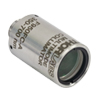 |
Thorlabs' High-NA Achromatic Collimators pair a meniscus lens with an achromatic doublet for high performance across the visible to near-infrared spectrum with low spherical aberration. Designed for use with high-NA multimode fiber, these collimators are ideal for Optogenetics and Fiber Photometry applications. |
| Reflective Collimators | 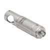 |
Thorlabs' metallic-coated Reflective Collimators are based on a 90° off-axis parabolic mirror. Mirrors, unlike lenses, have a focal length that remains constant over a broad wavelength range. Due to this intrinsic property, a parabolic mirror collimator does not need to be adjusted to accommodate various wavelengths of light, making them ideal for use with polychromatic light. Our reflective collimators are ideal for collimating single mode fiber but are not recommended for coupling into single mode fiber. We also offer a compact version of the protected-silver-coated reflective collimators that is directly compatible with our 16 mm cage system. |
| FiberPorts |  |
These compact, ultra-stable FiberPort micropositioners provide an easy-to-use, stable platform for coupling light into and out of FC/PC, FC/APC, or SMA terminated optical fibers. It can be used with single mode, multimode, or PM fibers and can be mounted onto a post, stage, platform, or laser. The built-in aspheric or achromatic lens is available with five different AR coatings and has five degrees of alignment adjustment (3 translational and 2 pitch). The compact size and long-term alignment stability make the FiberPort an ideal solution for fiber coupling, collimation, or incorporation into OEM systems. |
| Adjustable Fiber Collimators |  |
These collimators are designed to connect onto the end of an FC/PC, FC/APC, or SMA connector and contain an AR-coated aspheric lens. The distance between the aspheric lens and the tip of the fiber can be adjusted to compensate for focal length changes or to recollimate the beam at the wavelength and distance of interest. |
| Achromatic Fiber Collimators with Adjustable Focus | 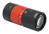 |
Thorlabs' Achromatic Fiber Collimators with Adjustable Focus are designed with an effective focal length (EFL) of 20 mm, 40 mm, or 80 mm, have optical elements broadband AR coated for one of three wavelength ranges, and are available with FC/PC, FC/APC, or SMA905 connectors. A four-element, air-spaced lens design produces superior beam quality (M2 close to 1) and less wavefront error when compared to aspheric lens collimators. These collimators can be used for free-space coupling into a fiber, collimation of output from a fiber, or in pairs for collimator-to-collimator coupling over long distances, which allows the beam to be manipulated prior to entering the second collimator. |
| Zoom Fiber Collimators |  |
These collimators provide a variable focal length between 6 and 18 mm, while maintaining the collimation of the beam. As a result, the size of the beam can be changed without altering the collimation. This universal device saves time previously spent searching for the best suited fixed fiber collimator and has a very broad range of applications. They are offered with FC/PC, FC/APC, or SMA905 connectors with three different antireflection wavelength ranges to choose from. |
| Single Mode Pigtailed Collimators |  |
Our single mode pigtailed collimators come with one meter of fiber, consist of an AR-coated aspheric lens pre-aligned with respect to a fiber, and are collimated at one of eight wavelengths: 532 nm, 633 nm, 780 nm, 850 nm, 1030 nm, 1064 nm, 1310 nm, or 1550 nm. Although it is possible to use the collimator at any wavelength within the coating range, the coupling loss will increase as the wavelength is detuned from the design wavelength. |
| Polarization Maintaining Pigtailed Collimators |  |
Our polarization maintaining pigtailed collimators come with one meter of fiber, consist of an AR-coated aspheric lens pre-aligned with respect to a fiber, and are collimated at one of five wavelengths: 633 nm, 780 nm, 980 nm, 1064 nm, or 1550 nm. Custom wavelengths and connectors are available as well. A line is engraved along the outside of the housing that is parallel to the fast axis. As such, it can be used as a reference when polarized light is launched accordingly. Although it is possible to use the collimator at any wavelength within the coating range, the coupling loss will increase as the wavelength is detuned from the design wavelength. |
| GRIN Fiber Collimators |  |
Thorlabs offers gradient index (GRIN) fiber collimators that are aligned at a variety of wavelengths from 630 to 1550 nm and have either FC terminated, APC terminated, or unterminated fibers. Our GRIN collimators feature a Ø1.8 mm clear aperture, are AR-coated to ensure low back reflection into the fiber, and are coupled to standard single mode or graded-index multimode fibers. |
| GRIN Lenses |  |
These graded-index (GRIN) lenses are AR coated for applications at 630, 830, 1060, 1300, or 1560 nm that require light to propagate through one fiber, then through a free-space optical system, and finally back into another fiber. They are also useful for coupling light from laser diodes into fibers, coupling the output of a fiber into a detector, or collimating laser light. Our GRIN lenses are designed to be used with our Pigtailed Glass Ferrules and GRIN/Ferrule sleeves. |
FiberPorts with an effective focal length of ≤7.5 mm can be used with both FC/PC and FC/APC connectors, as the 5-axis adjustment combined with the short focal length leads to negligible off-axis sensitivity.
| Item # | EFL | Input MFDa,b |
Output 1/e2 Waist Diametera |
Max Waist Distancea,c |
Divergencea | EFL Shiftd (Click for Plot) |
Lens Characteristics | Length Lg | |||
|---|---|---|---|---|---|---|---|---|---|---|---|
| CAe | NA | AR Rangef | Material (Click for Plot) |
||||||||
| PAF2-A4A | 4.0 mm | 3.5 µm | 0.65 mm | 378 mm | 0.875 mrad |
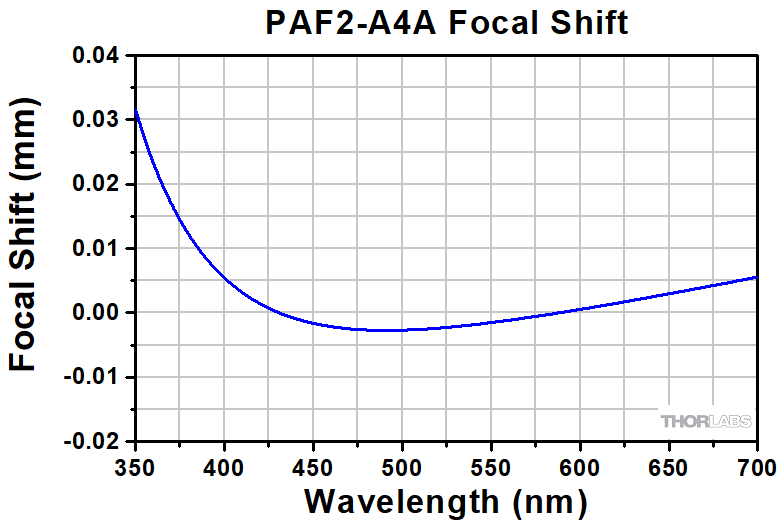 |
1.8 mm | 0.22 | 350 - 700 nm | N-SK16 / N-LASF9 | 0.70" (17.7 mm) |
| PAF2-A4B | 4.0 mm | 5.0 µm | 0.87 mm | 350 mm | 1.250 mrad |
 |
1.8 mm | 0.22 | 600 - 1050 nm | N-LAK22 / N-SF6HT | 0.70" (17.7 mm) |
| PAF2-A4C | 4.0 mm | 10.4 µm | 0.76 mm | 150 mm | 2.600 mrad |
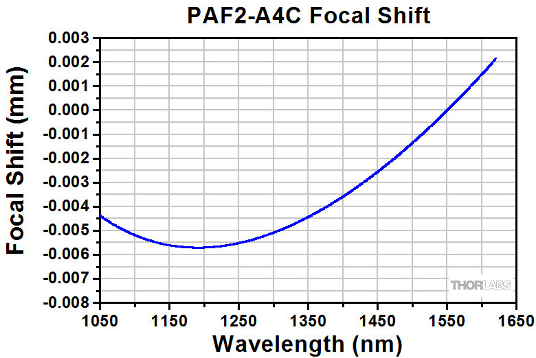 |
1.8 mm | 0.22 | 1050 - 1620 nm | S-PHM52/S-NPH2 | 0.70" (17.7 mm) |
| PAF2-A7A | 7.5 mm | 3.5 µm | 1.23 mm | 1323 mm | 0.467 mrad |
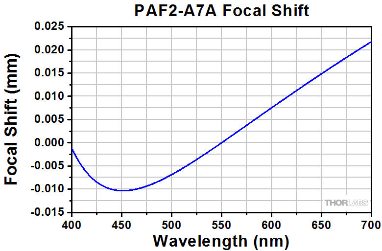 |
4.5 mm | 0.30 | 400 - 700 nm | N-BAF10 / N-SF6HT | 0.70" (17.7 mm) |
| PAF2-A7B | 7.5 mm | 5.0 µm | 1.62 mm | 1225 mm | 0.667 mrad |
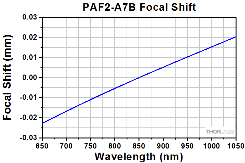 |
4.5 mm | 0.30 | 650 - 1050 nm | N-BAF10 / N-SF6HT | 0.70" (17.7 mm) |
| PAF2-A7C | 7.5 mm | 10.4 µm | 1.42 mm | 521 mm | 1.387 mrad |
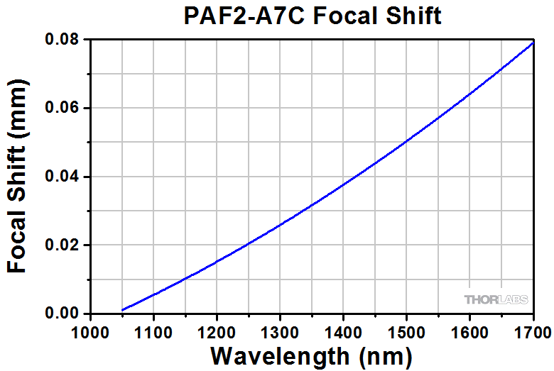 |
4.5 mm | 0.30 | 1050 - 1700 nm | N-LAK22 / N-SF6 | 0.70" (17.7 mm) |
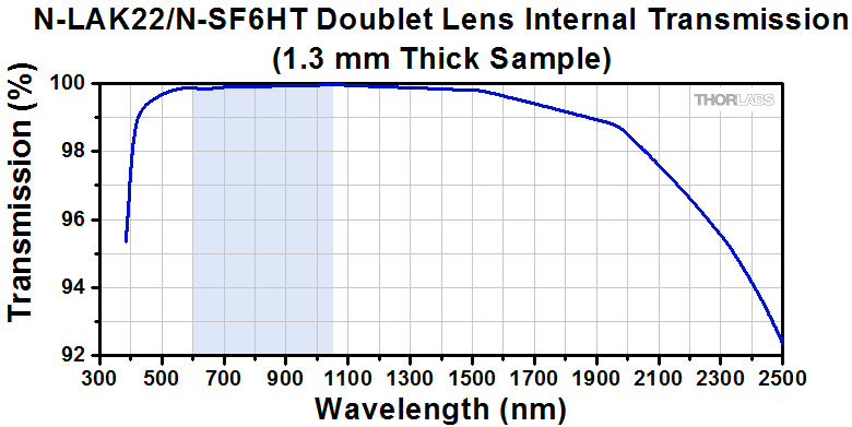
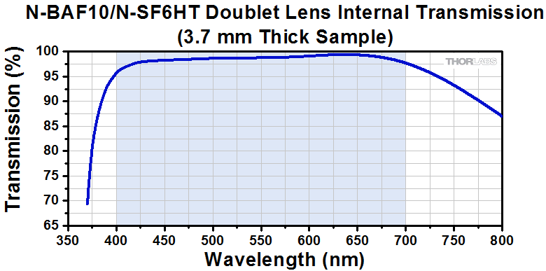
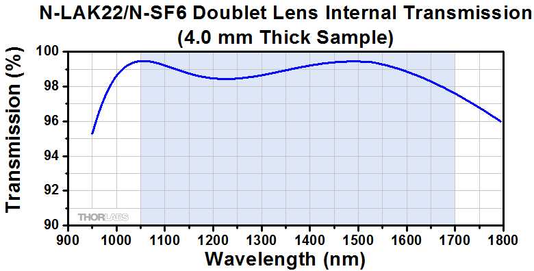
| Item # | EFL | Input MFDa,b |
Output 1/e2 Waist Diametera |
Max Waist Distancea,c | Divergencea | EFL Shiftd (Click for Plot) |
Lens Characteristics | Length Lg | |||
|---|---|---|---|---|---|---|---|---|---|---|---|
| CAe | NA | AR Rangef | Material (Click for Plot) |
||||||||
| PAF2P-A10A | 10.0 mm | 3.5 µm | 1.64 mm | 2349 mm | 0.350 mrad |
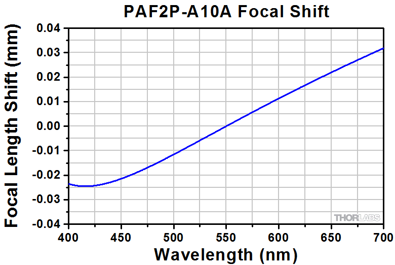 |
>4.5 mm | 0.23 | 400 - 700 nm | N-BAK4/SF5 | 0.87" (22.2 mm) |
| PAF2P-A10B | 10.0 mm | 5.0 µm | 2.16 mm | 2175 mm | 0.500 mrad |  |
>4.5 mm | 0.23 | 650 - 1050 nm | N-LAK22/N-SF6HT | 0.87" (22.2 mm) |
| PAF2P-A10C | 10.0 mm | 10.4 µm | 1.99 mm | 922 mm | 0.990 mrad | 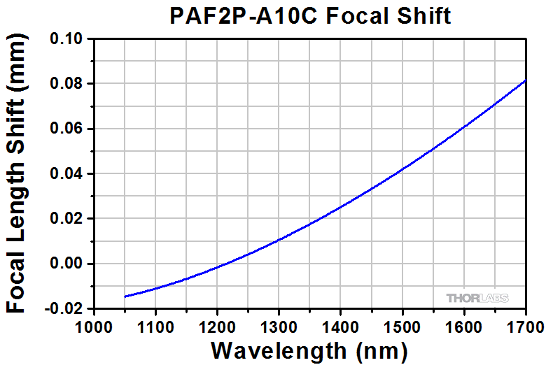 |
>4.5 mm | 0.23 | 1050 - 1700 nm | N-LAK22/N-SF6 | 0.87" (22.2 mm) |
| PAF2P-A15A | 15.0 mm | 3.5 µm | 2.46 mm | 5277 mm | 0.233 mrad | 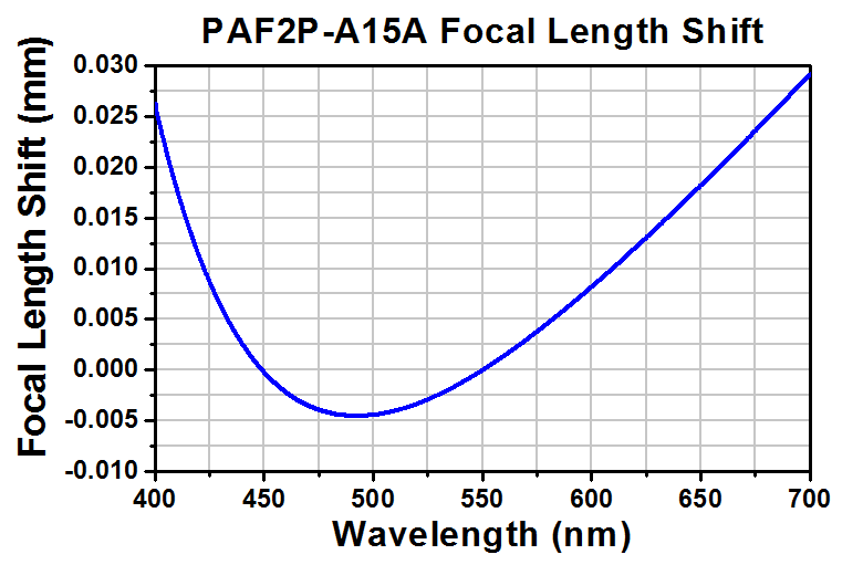 |
>4.5 mm | 0.15 | 400 - 700 nm | N-BK7/SF2 | 0.87" (22.2 mm) |
| PAF2P-A15B | 15.0 mm | 5.0 µm | 3.25 mm | 4885 mm | 0.333 mrad |
 |
>4.5 mm | 0.15 | 650 - 1050 nm | N-LAK22/N-SF6HT | 0.87" (22.2 mm) |
| PAF2P-A15C | 15.0 mm | 10.4 µm | 2.85 mm | 2068 mm | 0.693 mrad |
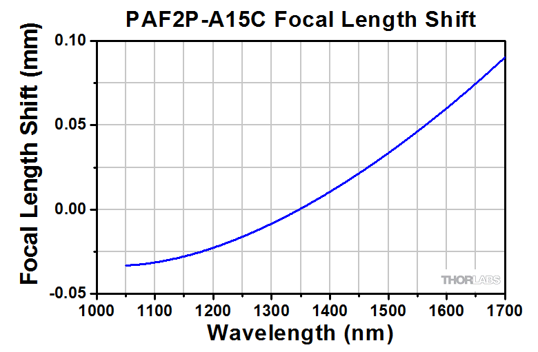 |
>4.5 mm | 0.15 | 1050 - 1700 nm | N-BAF10/N-SF6 | 0.87" (22.2 mm) |
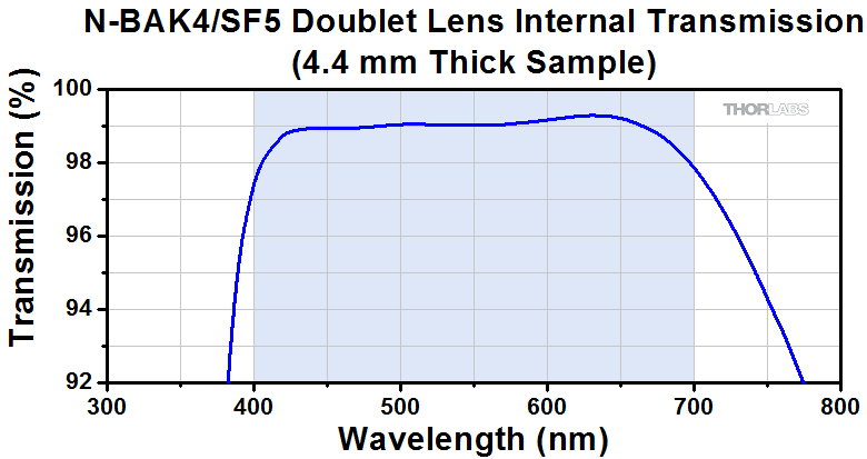
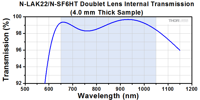
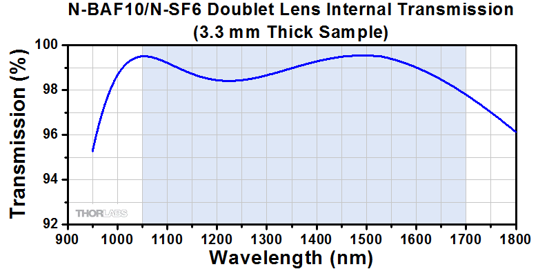
| Item # | EFL | Input MFDa,b |
Output 1/e2 Waist Diametera |
Max Waist Distancea,c | Divergencea | EFL Shiftd (Click for Plot) |
Lens Characteristics | Length Lg | |||
|---|---|---|---|---|---|---|---|---|---|---|---|
| CAe | NA | AR Rangef | Material (Click for Plot) |
||||||||
| PAF2A-A10A | 10.0 mm | 3.5 µm | 1.64 mm | 2349 mm | 0.350 mrad |
 |
>4.5 mm | 0.23 | 400 - 700 nm | N-BAK4/SF5 | 0.88" (22.4 mm) |
| PAF2A-A10B | 10.0 mm | 5.0 µm | 2.16 mm | 2175 mm | 0.500 mrad | 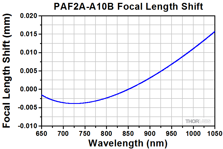 |
>4.5 mm | 0.23 | 650 - 1050 nm | N-LAK22/N-SF6HT | 0.88" (22.4 mm) |
| PAF2A-A10C | 10.0 mm | 10.4 µm | 1.99 mm | 922 mm | 0.990 mrad |  |
>4.5 mm | 0.23 | 1050 - 1700 nm | N-LAK22/N-SF6 | 0.88" (22.4 mm) |
| PAF2A-A15A | 15.0 mm | 3.5 µm | 2.46 mm | 5277 mm | 0.233 mrad |  |
>4.5 mm | 0.15 | 400 - 700 nm | N-BK7/SF2 | 0.88" (22.4 mm) |
| PAF2A-A15B | 15.0 mm | 5.0 µm | 3.25 mm | 4885 mm | 0.333 mrad |
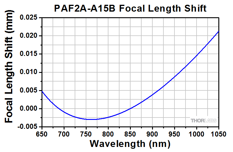 |
>4.5 mm | 0.15 | 650 - 1050 nm | N-LAK22/N-SF6HT | 0.88" (22.4 mm) |
| PAF2A-A15C | 15.0 mm | 10.4 µm | 2.85 mm | 2068 mm | 0.693 mrad |
 |
>4.5 mm | 0.15 | 1050 - 1700 nm | N-BAF10/N-SF6 | 0.88" (22.4 mm) |
| Item # | EFL | Input MFDa,b |
Output 1/e2 Waist Diametera |
Max Waist Distancea,c |
Divergencea | EFL Shiftd (Click for Plot) |
Lens Characteristics | Length Lg | |||
|---|---|---|---|---|---|---|---|---|---|---|---|
| CAe | NA | AR Rangef | Material (Click for Plot) |
||||||||
| PAF2S-A4A | 4.0 mm | 3.5 µm | 0.65 mm | 378 mm | 0.875 mrad |
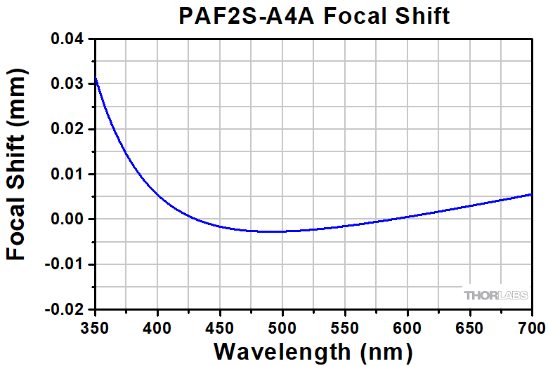 |
1.8 mm | 0.22 | 350 - 700 nm | N-SK16 / N-LASF9 | 0.87" (22.0 mm) |
| PAF2S-A4B | 4.0 mm | 5.0 µm | 0.87 mm | 350 mm | 1.250 mrad |
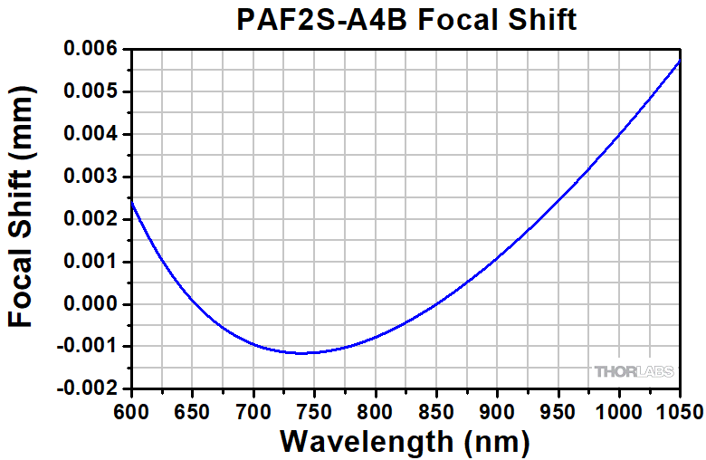 |
1.8 mm | 0.22 | 600 - 1050 nm | N-LAK22 / N-SF6HT | 0.87" (22.0 mm) |
| PAF2S-A4C | 4.0 mm | 10.4 µm | 0.76 mm | 150 mm | 2.600 mrad |
 |
1.8 mm | 0.22 | 1050 - 1620 nm | S-PHM52/S-NPH2 | 0.87" (22.0 mm) |
| PAF2S-A7A | 7.5 mm | 3.5 µm | 1.23 mm | 1323 mm | 0.467 mrad |
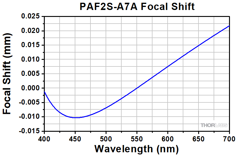 |
4.5 mm | 0.30 | 400 - 700 nm | N-BAF10 / N-SF6HT | 0.87" (22.0 mm) |
| PAF2S-A7B | 7.5 mm | 5.0 µm | 1.62 mm | 1225 mm | 0.667 mrad |
 |
4.5 mm | 0.30 | 650 - 1050 nm | N-BAF10 / N-SF6HT | 0.87" (22.0 mm) |
| PAF2S-A7C | 7.5 mm | 10.4 µm | 1.42 mm | 521 mm | 1.387 mrad |
 |
4.5 mm | 0.30 | 1050 - 1700 nm | N-LAK22 / N-SF6 | 0.87" (22.0 mm) |
FiberPorts with an effective focal length of ≤7.5 mm can be used with both FC/PC and FC/APC connectors, as the 5-axis adjustment combined with the short focal length leads to negligible off-axis sensitivity.
| Item # | EFL | Input MFDa,b | Output 1/e2 Waist Diametera |
Max Waist Distancea,c |
Divergencea | Lens Characteristics | Length Lf | |||
|---|---|---|---|---|---|---|---|---|---|---|
| CAd | NA | AR Rangee | Material | |||||||
| PAF2-2A | 2.0 mm | 3.5 µm | 0.33 mm | 96 mm | 1.750 mrad | 2.0 mm | 0.50 | 350 - 700 nm | D-ZLAF52LA | 0.70" (17.7 mm) |
| PAF2-2B | 2.0 mm | 5.0 µm | 0.43 mm | 89 mm | 2.500 mrad | 2.0 mm | 0.50 | 600 - 1050 nm | D-ZLAF52LA | 0.70" (17.7 mm) |
| PAF2-2C | 2.0 mm | 10.4 µm | 0.38 mm | 38 mm | 5.200 mrad | 2.0 mm | 0.50 | 1050 - 1620 nm | D-ZLAF52LA | 0.70" (17.7 mm) |
| PAF2-4E | 4.0 mm | 14.80 µm | 1.17 mm | 162 mm | 3.700 mrad | 5.0 mm | 0.56 | 2.0 - 5.0 µm | Black Diamond-2 | 0.70" (17.7 mm) |
| PAF2-5A | 4.6 mm | 3.5 µm | 0.75 mm | 499 mm | 0.761 mrad | 4.9 mm | 0.53 | 350 - 700 nm | H-LAK54 | 0.70" (17.7 mm) |
| PAF2-5B | 4.6 mm | 5.0 µm | 1.00 mm | 463 mm | 1.087 mrad | 4.9 mm | 0.53 | 600 - 1050 nm | H-LAK54 | 0.70" (17.7 mm) |
| PAF2-5C | 4.6 mm | 10.4 µm | 0.87 mm | 198 mm | 2.261 mrad | 4.9 mm | 0.53 | 1050 - 1620 nm | H-LAK54 | 0.70" (17.7 mm) |
| PAF2-5D | 4.6 mm | 13.0 µm | 0.90 mm | 164 mm | 2.826 mrad | 4.9 mm | 0.53 | 1.8 - 2.4 µm | H-LAK54 | 0.70" (17.7 mm) |
| PAF2-7A | 7.5 mm | 3.5 µm | 1.23 mm | 1323 mm | 0.467 mrad | 4.5 mm | 0.30 | 350 - 700 nm | H-LAK54 | 0.70" (17.7 mm) |
| PAF2-7B | 7.5 mm | 5.0 µm | 1.62 mm | 1225 mm | 0.667 mrad | 4.5 mm | 0.30 | 600 - 1050 nm | H-LAK54 | 0.70" (17.7 mm) |
| PAF2-7C | 7.5 mm | 10.4 µm | 1.42 mm | 521 mm | 1.387 mrad | 4.5 mm | 0.30 | 1050 - 1620 nm | H-LAK54 | 0.70" (17.7 mm) |
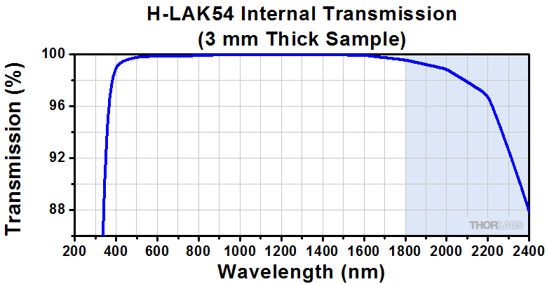
| Item # | EFL | Input MFDa,b | Output 1/e2 Waist Diametera |
Max Waist Distancea,c |
Divergencea | Lens Characteristics | Length Lf | |||
|---|---|---|---|---|---|---|---|---|---|---|
| CAd | NA | AR Rangee | Material | |||||||
| PAF2P-11A | 11.0 mm | 3.5 µm | 1.80 mm | 2841 mm | 0.318 mrad | 4.4 mm | 0.20 | 350 - 700 nm | H-LAK54 | 0.87" (22.0 mm) |
| PAF2P-11B | 11.0 mm | 5.0 µm | 2.38 mm | 2630 mm | 0.455 mrad | 4.4 mm | 0.20 | 600 - 1050 nm | H-LAK54 | 0.87" (22.0 mm) |
| PAF2P-11C | 11.0 mm | 10.4 µm | 2.09 mm | 1115 mm | 0.945 mrad | 4.4 mm | 0.20 | 1050 - 1620 nm | H-LAK54 | 0.87" (22.0 mm) |
| PAF2P-11D | 11.0 mm | 13.0 µm | 2.15 mm | 921 mm | 1.182 mrad | 4.4 mm | 0.20 | 1.8 - 2.4 µm | H-LAK54 | 0.87" (22.0 mm) |
| PAF2P-11E | 11.0 mm | 14.80 µm | 3.21 mm | 1203 mm | 1.345 mrad | 4.0 mm | 0.18 | 2.0 - 5.0 µm | Black Diamond-2 | 0.87" (22.0 mm) |
| PAF2P-15A | 15.3 mm | 3.5 µm | 2.52 mm | 5490 mm | 0.227 mrad | 5.0 mm | 0.16 | 350 - 700 nm | D-ZK3 | 0.87" (22.0 mm) |
| PAF2P-15B | 15.3 mm | 5.0 µm | 3.33 mm | 5082 mm | 0.325 mrad | 5.0 mm | 0.16 | 600 - 1050 nm | D-ZK3 | 0.87" (22.0 mm) |
| PAF2P-15C | 15.3 mm | 10.4 µm | 2.92 mm | 2151 mm | 0.675 mrad | 5.0 mm | 0.16 | 1050 - 1620 nm | D-ZK3 | 0.87" (22.0 mm) |
| PAF2P-15D | 15.3 mm | 13.0 µm | 3.00 mm | 1775 mm | 0.850 mrad | 5.0 mm | 0.16 | 1.8 - 2.4 µm | D-ZK3 | 0.87" (22.0 mm) |
| PAF2P-18A | 18.4 mm | 3.5 µm | 3.01 mm | 7936 mm | 0.190 mrad | 5.5 mm | 0.15 | 350 - 700 nm | D-ZK3 | 0.87" (22.0 mm) |
| PAF2P-18B | 18.4 mm | 5.0 µm | 3.98 mm | 7347 mm | 0.272 mrad | 5.5 mm | 0.15 | 600 - 1050 nm | D-ZK3 | 0.87" (22.0 mm) |
| PAF2P-18C | 18.4 mm | 10.4 µm | 3.49 mm | 3107 mm | 0.565 mrad | 5.5 mm | 0.15 | 1050 - 1620 nm | D-ZK3 | 0.87" (22.0 mm) |
| PAF2P-18D | 18.4 mm | 13.0 µm | 3.60 mm | 2564 mm | 0.707 mrad | 5.5 mm | 0.15 | 1.8 - 2.4 µm | D-ZK3 | 0.87" (22.0 mm) |
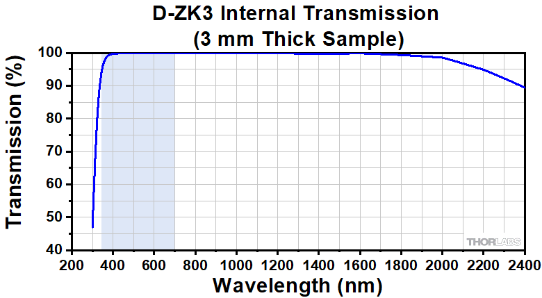
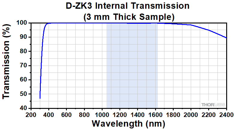
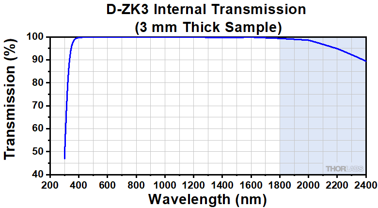
| Item # | EFL | Input MFDa,b | Output 1/e2 Waist Diametera |
Max Waist Distancea,c |
Divergencea | Lens Characteristics | Length Lf | |||
|---|---|---|---|---|---|---|---|---|---|---|
| CAd | NA | AR Rangee | Material | |||||||
| PAF2A-2A | 2.0 mm | 3.5 µm | 0.33 mm | 96 mm | 1.750 mrad | 2.0 mm | 0.50 | 350 - 700 nm | D-ZLAF52LA | 0.70" (17.9 mm) |
| PAF2A-2B | 2.0 mm | 5.0 µm | 0.43 mm | 89 mm | 2.500 mrad | 2.0 mm | 0.50 | 600 - 1050 nm | D-ZLAF52LA | 0.70" (17.9 mm) |
| PAF2A-2C | 2.0 mm | 10.4 µm | 0.38 mm | 38 mm | 5.200 mrad | 2.0 mm | 0.50 | 1050 - 1620 nm | D-ZLAF52LA | 0.70" (17.9 mm) |
| PAF2A-5A | 4.6 mm | 3.5 µm | 0.75 mm | 499 mm | 0.761 mrad | 4.9 mm | 0.53 | 350 - 700 nm | H-LAK54 | 0.70" (17.9 mm) |
| PAF2A-5B | 4.6 mm | 5.0 µm | 1.00 mm | 463 mm | 1.087 mrad | 4.9 mm | 0.53 | 600 - 1050 nm | H-LAK54 | 0.70" (17.9 mm) |
| PAF2A-5C | 4.6 mm | 10.4 µm | 0.87 mm | 198 mm | 2.261 mrad | 4.9 mm | 0.53 | 1050 - 1620 nm | H-LAK54 | 0.70" (17.9 mm) |
| PAF2A-7A | 7.5 mm | 3.5 µm | 1.23 mm | 1323 mm | 0.467 mrad | 4.5 mm | 0.30 | 350 - 700 nm | H-LAK54 | 0.70" (17.9 mm) |
| PAF2A-7B | 7.5 mm | 5.0 µm | 1.62 mm | 1225 mm | 0.667 mrad | 4.5 mm | 0.30 | 600 - 1050 nm | H-LAK54 | 0.70" (17.9 mm) |
| PAF2A-7C | 7.5 mm | 10.4 µm | 1.42 mm | 521 mm | 1.387 mrad | 4.5 mm | 0.30 | 1050 - 1620 nm | H-LAK54 | 0.70" (17.9 mm) |
| PAF2A-11A | 11.0 mm | 3.5 µm | 1.80 mm | 2841 mm | 0.318 mrad | 4.4 mm | 0.20 | 350 - 700 nm | H-LAK54 | 0.88" (22.4 mm) |
| PAF2A-11B | 11.0 mm | 5.0 µm | 2.38 mm | 2630 mm | 0.455 mrad | 4.4 mm | 0.20 | 600 - 1050 nm | H-LAK54 | 0.88" (22.4 mm) |
| PAF2A-11C | 11.0 mm | 10.4 µm | 2.09 mm | 1115 mm | 0.945 mrad | 4.4 mm | 0.20 | 1050 - 1620 nm | H-LAK54 | 0.88" (22.4 mm) |
| PAF2A-11D | 11.0 mm | 13.0 µm | 2.15 mm | 921 mm | 1.182 mrad | 4.4 mm | 0.20 | 1.8 - 2.4 µm | H-LAK54 | 0.88" (22.4 mm) |
| PAF2A-11E | 11.0 mm | 14.80 µm | 3.21 mm | 1203 mm | 1.345 mrad | 4.0 mm | 0.18 | 2.0 - 5.0 µm | Black Diamond-2 | 0.88" (22.4 mm) |
| PAF2A-15A | 15.3 mm | 3.5 µm | 2.52 mm | 5490 mm | 0.227 mrad | 5.0 mm | 0.16 | 350 - 700 nm | D-ZK3 | 0.88" (22.4 mm) |
| PAF2A-15B | 15.3 mm | 5.0 µm | 3.33 mm | 5082 mm | 0.325 mrad | 5.0 mm | 0.16 | 600 - 1050 nm | D-ZK3 | 0.88" (22.4 mm) |
| PAF2A-15C | 15.3 mm | 10.4 µm | 2.92 mm | 2151 mm | 0.675 mrad | 5.0 mm | 0.16 | 1050 - 1620 nm | D-ZK3 | 0.88" (22.4 mm) |
| PAF2A-15D | 15.3 mm | 13.0 µm | 3.00 mm | 1775 mm | 0.850 mrad | 5.0 mm | 0.16 | 1.8 - 2.4 µm | D-ZK3 | 0.88" (22.4 mm) |
| PAF2A-18A | 18.4 mm | 3.5 µm | 3.01 mm | 7936 mm | 0.190 mrad | 5.5 mm | 0.15 | 350 - 700 nm | D-ZK3 | 0.88" (22.4 mm) |
| PAF2A-18B | 18.4 mm | 5.0 µm | 3.98 mm | 7347 mm | 0.272 mrad | 5.5 mm | 0.15 | 600 - 1050 nm | D-ZK3 | 0.88" (22.4 mm) |
| PAF2A-18C | 18.4 mm | 10.4 µm | 3.49 mm | 3107 mm | 0.565 mrad | 5.5 mm | 0.15 | 1050 - 1620 nm | D-ZK3 | 0.88" (22.4 mm) |
| PAF2A-18D | 18.4 mm | 13.0 µm | 3.60 mm | 2564 mm | 0.707 mrad | 5.5 mm | 0.15 | 1.8 - 2.4 µm | D-ZK3 | 0.88" (22.4 mm) |
| Item # | EFL | Input MFDa,b | Output 1/e2 Waist Diametera |
Max Waist Distancea,c |
Divergencea | Lens Characteristics | Length Lf | |||
|---|---|---|---|---|---|---|---|---|---|---|
| CAd | NA | AR Rangee | Material | |||||||
| PAF2S-2A | 2.0 mm | 3.5 µm | 0.33 mm | 96 mm | 1.750 mrad | 2.0 mm | 0.50 | 350 - 700 nm | D-ZLAF52LA | 0.87" (22.0 mm) |
| PAF2S-2B | 2.0 mm | 5.0 µm | 0.43 mm | 89 mm | 2.500 mrad | 2.0 mm | 0.50 | 600 - 1050 nm | D-ZLAF52LA | 0.87" (22.0 mm) |
| PAF2S-2C | 2.0 mm | 10.4 µm | 0.38 mm | 38 mm | 5.200 mrad | 2.0 mm | 0.50 | 1050 - 1620 nm | D-ZLAF52LA | 0.87" (22.0 mm) |
| PAF2S-4E | 4.0 mm | 14.80 µm | 1.17 mm | 162 mm | 3.700 mrad | 5.0 mm | 0.56 | 2.0 - 5.0 µm | Black Diamond-2 | 0.87" (22.0 mm) |
| PAF2S-5A | 4.6 mm | 3.5 µm | 0.75 mm | 499 mm | 0.761 mrad | 4.9 mm | 0.53 | 350 - 700 nm | H-LAK54 | 0.87" (22.0 mm) |
| PAF2S-5B | 4.6 mm | 5.0 µm | 1.00 mm | 463 mm | 1.087 mrad | 4.9 mm | 0.53 | 600 - 1050 nm | H-LAK54 | 0.87" (22.0 mm) |
| PAF2S-5C | 4.6 mm | 10.4 µm | 0.87 mm | 198 mm | 2.261 mrad | 4.9 mm | 0.53 | 1050 - 1620 nm | H-LAK54 | 0.87" (22.0 mm) |
| PAF2S-5D | 4.6 mm | 13.0 µm | 0.90 mm | 164 mm | 2.826 mrad | 4.9 mm | 0.53 | 1.8 - 2.4 µm | H-LAK54 | 0.87" (22.0 mm) |
| PAF2S-7A | 7.5 mm | 3.5 µm | 1.23 mm | 1323 mm | 0.467 mrad | 4.5 mm | 0.30 | 350 - 700 nm | H-LAK54 | 0.87" (22.0 mm) |
| PAF2S-7B | 7.5 mm | 5.0 µm | 1.62 mm | 1225 mm | 0.667 mrad | 4.5 mm | 0.30 | 600 - 1050 nm | H-LAK54 | 0.87" (22.0 mm) |
| PAF2S-7C | 7.5 mm | 10.4 µm | 1.42 mm | 521 mm | 1.387 mrad | 4.5 mm | 0.30 | 1050 - 1620 nm | H-LAK54 | 0.87" (22.0 mm) |
| PAF2S-11A | 11.0 mm | 3.5 µm | 1.80 mm | 2841 mm | 0.318 mrad | 4.4 mm | 0.20 | 350 - 700 nm | H-LAK54 | 1.04" (26.5 mm) |
| PAF2S-11B | 11.0 mm | 5.0 µm | 2.38 mm | 2630 mm | 0.455 mrad | 4.4 mm | 0.20 | 600 - 1050 nm | H-LAK54 | 1.04" (26.5 mm) |
| PAF2S-11C | 11.0 mm | 10.4 µm | 2.09 mm | 1115 mm | 0.945 mrad | 4.4 mm | 0.20 | 1050 - 1620 nm | H-LAK54 | 1.04" (26.5 mm) |
| PAF2S-11D | 11.0 mm | 13.0 µm | 2.15 mm | 921 mm | 1.182 mrad | 4.4 mm | 0.20 | 1.8 - 2.4 µm | H-LAK54 | 1.04" (26.5 mm) |
| PAF2S-11E | 11.0 mm | 14.80 µm | 3.21 mm | 1203 mm | 1.345 mrad | 4.0 mm | 0.18 | 2.0 - 5.0 µm | Black Diamond-2 | 1.04" (26.5 mm) |
| PAF2S-15A | 15.3 mm | 3.5 µm | 2.52 mm | 5490 mm | 0.227 mrad | 5.0 mm | 0.16 | 350 - 700 nm | D-ZK3 | 1.04" (26.5 mm) |
| PAF2S-15B | 15.3 mm | 5.0 µm | 3.33 mm | 5082 mm | 0.325 mrad | 5.0 mm | 0.16 | 600 - 1050 nm | D-ZK3 | 1.04" (26.5 mm) |
| PAF2S-15C | 15.3 mm | 10.4 µm | 2.92 mm | 2151 mm | 0.675 mrad | 5.0 mm | 0.16 | 1050 - 1620 nm | D-ZK3 | 1.04" (26.5 mm) |
| PAF2S-15D | 15.3 mm | 13.0 µm | 3.00 mm | 1775 mm | 0.850 mrad | 5.0 mm | 0.16 | 1.8 - 2.4 µm | D-ZK3 | 1.04" (26.5 mm) |
| PAF2S-18A | 18.4 mm | 3.5 µm | 3.01 mm | 7936 mm | 0.190 mrad | 5.5 mm | 0.15 | 350 - 700 nm | D-ZK3 | 1.04" (26.5 mm) |
| PAF2S-18B | 18.4 mm | 5.0 µm | 3.98 mm | 7347 mm | 0.272 mrad | 5.5 mm | 0.15 | 600 - 1050 nm | D-ZK3 | 1.04" (26.5 mm) |
| PAF2S-18C | 18.4 mm | 10.4 µm | 3.49 mm | 3107 mm | 0.565 mrad | 5.5 mm | 0.15 | 1050 - 1620 nm | D-ZK3 | 1.04" (26.5 mm) |
| PAF2S-18D | 18.4 mm | 13.0 µm | 3.60 mm | 2564 mm | 0.707 mrad | 5.5 mm | 0.15 | 1.8 - 2.4 µm | D-ZK3 | 1.04" (26.5 mm) |