 Products Home / Lab Supplies / Light Accessories / Alignment Tools / Anodized Aluminum Alignment Targets
Anodized Aluminum Alignment Targets
- Unmounted, Drop-In, or Threaded Alignment Targets for Visible Light
- For Use with Cage Systems, Lens Mounts, or Lens Tubes
- Laser-Engraved Rings or Axes to Aid Alignment
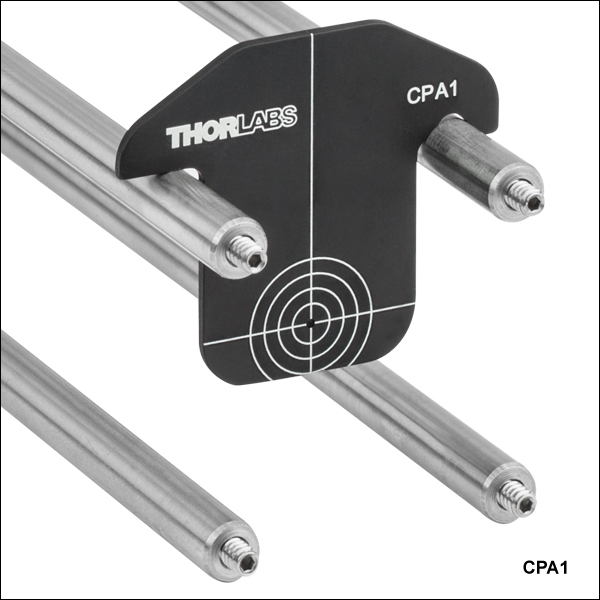
CPA1
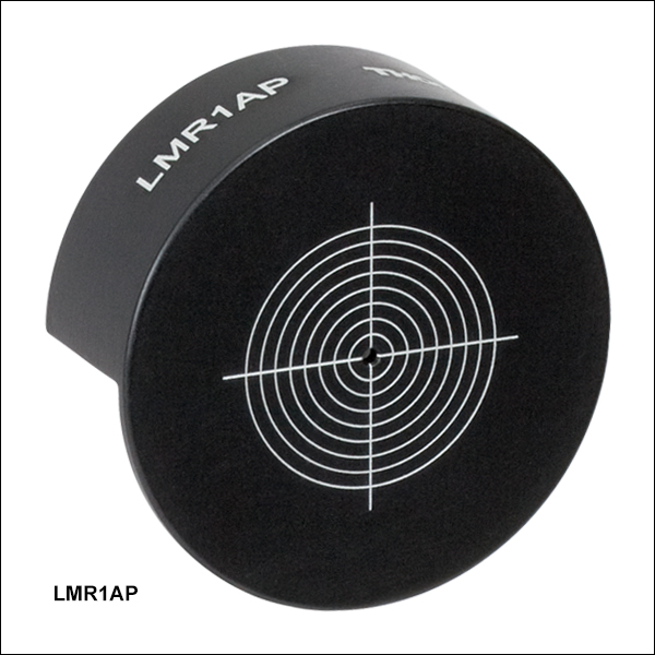
LMR1AP
SM1A7
AP2.5
SM1AP1


Please Wait

Features
- 16 mm, 30 mm, and 60 mm Cage Alignment Plates
- Lens Mount Alignment Plates for Fixed Lens Mounts and Lens Tubes
- Externally SM05 (0.535"-40) and SM1 (1.035"-40) Threaded Alignment Disks
- Aperture Plates for Ø1/2" Optic Mounts
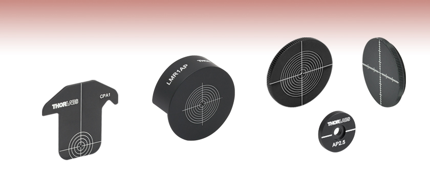
These alignment targets for visible light help simplify the process of aligning an optical system. All of these targets are made out of anodized aluminum. Each of these targets features either laser-engraved concentric circles, graduated X- and Y-axes, or a single engraved axis for optimal visual alignment of the beam. Options are available for compatibility with cage systems, lens mounts, and lens tubes.
Other Alignment Options
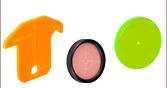
In addition to our traditional alignment targets, we offer fluorescing alignment targets and detector cards for aligning UV or IR light.

Insights into Aligning a Laser Beam
When installing a laser in an optical setup, it is good practice to start by leveling and orienting its beam so that it travels along a well-defined path. When the beam is prepared this way, not only is it easier to then divert the beam and route it through the optical elements in the system, but the results provided by tuning the system's alignment are more predictable and repeatable. The following sections describe how to:
- Level and Align the Laser Beam's Pointing Angle
- Divert the Beam and Align it to Follow a Desired Path
Click here for more Insights about lab practices and equipment.
Level and Align the Laser Beam's Pointing Angle
0:00 - Introduction
1:25 - Level and Align the Laser Beam's Pointing Angle
4:09 - Divert the Beam and Align it to Follow a Desired Path
Click to Enlarge
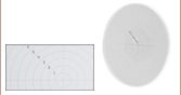
Figure 2: The beam can be aligned to travel parallel to a line of tapped holes in the optical table. The yaw adjustment on the kinematic mount adjusts the beam angle, so that the beam remains incident on the ruler's vertical reference line as the ruler slides along the line of tapped holes.
Click to Enlarge
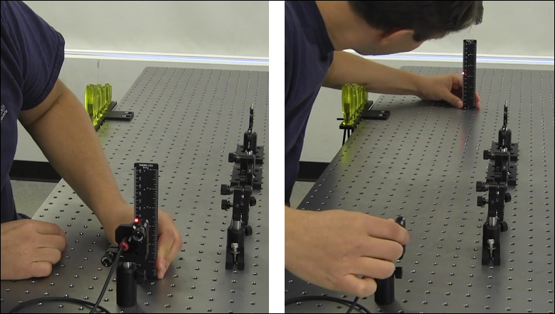
Figure 1: Leveling the beam path with respect to the surface of an optical table requires using the pitch adjustment on the kinematic laser mount (Figure 2). The beam is parallel to the table's surface when measurements of the beam height near to (left) and far from (right) the laser's front face are equal.
Pitch (tip) and yaw (tilt) adjustments provided by a kinematic mount can be used to make fine corrections to a laser beam's angular orientation or pointing angle. This angular tuning capability is convenient when aligning a collimated laser beam to be level with respect to a reference plane, such as the surface of an optical table, and when aligning with respect to a particular direction in that plane, such as along a line of tapped holes in the table.
Before Using the Mount's Adjusters
First, rotate each adjuster on the kinematic mount to the middle of its travel range. This reduces the risk of running out of adjustment range, and the positioning stability is frequently better when at the center of an adjuster's travel range.
Then, make coarse corrections to the laser's height, position, and orientation. This can be done by adjusting the optomechanical components, such as a post and post holder, supporting the laser. Ensure all locking screws are tightened after the adjustments are complete.
Level the Beam Parallel to the Table's Surface
Leveling the laser beam is an iterative process that requires an alignment tool and the fine control provided by the mount's pitch adjuster.
Begin each iteration by measuring the height of the beam close to and far from the laser (Figure 1). A larger distance between the two measurements increases accuracy. If the beam height at the two locations differs, place the ruler in the more distant position. Adjust the pitch on the kinematic mount until the beam height at that location matches the height measured close to the laser. Iterate until the beam height at both positions is the same.
More than one iteration is necessary, because adjusting the pitch of the laser mount adjusts the height of the laser emitter. In the video for example, the beam height close to the laser was initially 82 mm, but it increased to 83 mm after the pitch was adjusted during the first iteration.
If the leveled beam is at an inconvenient height, the optomechanical components supporting the laser can be adjusted to change its height. Alternatively, two steering mirrors can be placed after the laser and aligned using a different procedure, which is detailed in the section. Steering mirrors are particularly useful for adjusting beam height and orientation of a fixed laser.
Orient the Beam Along a Row of Tapped Holes
Aligning the beam parallel to a row of tapped holes in the table is another iterative process, which requires an alignment tool and tuning of the mount's yaw adjuster.
The alignment tool is needed to translate the reference line provided by the tapped holes into the plane of the laser beam. The ruler can serve as this tool, when an edge on the ruler's base is aligned with the edges of the tapped holes that define the line (Figure 2).
The relative position of the beam with respect to the reference line on the table can be evaluated by judging the distance between the laser spot and vertical reference feature on the ruler. Vertical features on this ruler include its edges, as well as the columns formed by different-length rulings. If these features are not sufficient and rulings are required, a horizontally oriented ruler can be attached using a BHMA1 mounting bracket.
In the video, when the ruler was aligned to the tapped holes and positioned close to the laser, the beam's edge and the ends of the 1 mm rulings coincided. When the ruler was moved to a farther point on the reference line, the beam's position on the ruler was horizontally shifted. With the ruler at that distant position, the yaw adjustment on the mount was tuned until the beam's edge again coincided with the 1 mm rulings. The ruler was then moved closer to the laser to observe the effect of adjusting the mount on the beam's position. This was iterated as necessary.
Divert the Beam and Align it to Follow a Desired Path
The first steering mirror reflects the beam along a line that crosses the new beam path. A second steering mirror is needed to level the beam and align it along the new path. The procedure of aligning a laser beam with two steering mirrors is sometimes described as walking the beam, and the result can be referred to as a folded beam path. In the example shown in the video above, two irises are used to align the beam to the new path, which is parallel to the surface of the optical table and follows a row of tapped holes.
Click to Enlarge
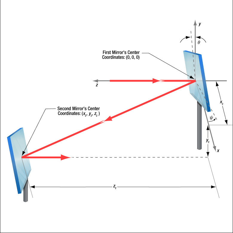
Figure 3: The beam reflected from Mirror 1 will be incident on Mirror 2, if Mirror 1 is rotated around the x- and y-axes by angles θ and ψ, respectively. Both angles affect each coordinate (x2 , y2 , z2 ) of Mirror 2's center. Mirror 1's rotation around the x-axis is limited by the travel range of the mount's pitch (tip) adjuster, which limits Mirror 2's position and height options.
Click to Enlarge
Figure 5: The adjusters on the second kinematic mirror are used to align the beam on the second iris.
Click to Enlarge
Figure 4: The adjusters on the first kinematic mirror mount are tuned to position the laser spot on the aperture of the first iris.
Setting the Heights of the Mirrors
The center of the first mirror should match the height of the input beam path, since the first mirror diverts the beam from this path and relays it to a point on the second mirror. The center of the second mirror should be set at the height of the new beam path.
Iris Setup
The new beam path is defined by the irises, which in the video have matching heights to ensure the path is level with respect to the surface of the table. A ruler or calipers can be used to set the height of the irises in their mounts with modest precision.
When an iris is closed, its aperture may not be perfectly centered. Because of this, switching the side of the iris that faces the beam can cause the position of the aperture to shift. It is good practice to choose one side of the iris to face the beam and then maintain that orientation during setup and use.
Component Placement and Coarse Alignment
Start by rotating the adjusters on both mirrors to the middle of their travel ranges. Place the first mirror in the input beam path, and determine a position for the second mirror in the new beam path (Figure 3). The options are notably restricted by the travel range of the first mirror mount's pitch (tip) actuator, since it limits the mirror's rotation (θ ) around its x-axis. In addition to the pitch, the yaw (tilt) of the first mirror must also be considered when choosing a position
After placing the second mirror on the new beam path, position both irises after the second mirror on the desired beam path. Locate the first iris near the second mirror and the second iris as far away as possible.
While maintaining the two mirrors' heights and without touching the yaw adjusters, rotate the first mirror to direct the beam towards the second mirror. Adjust the pitch adjuster on the first mirror to place the laser spot near the center of the second mirror. Then, rotate the second mirror to direct the beam roughly along the new beam path.
First Hit a Point on the Path, then Orient
The first mirror is used to steer the beam to the point on the second mirror that is in line with the new beam path. To do this, tune the first mirror's adjusters while watching the position of the laser spot on the first iris (Figure 4). The first step is complete when the laser spot is centered on the iris' aperture.
The second mirror is used to steer the beam into alignment with the new beam path. Tune the adjusters on the second mirror to move the laser spot over the second iris' aperture (Figure 5). The pitch adjuster levels the beam, and the yaw adjuster shifts it laterally. If the laser spot disappears from the second iris, it is because the laser spot on the second mirror has moved away from the new beam path.
Tune the first mirror's adjusters to reposition the beam on the second mirror so that the laser spot is centered on the first iris' aperture. Resume tuning the adjusters on the second mirror to direct the laser spot over the aperture on the second iris. Iterate until the laser beam passes directly through the center of both irises, as shown in the video. If any adjuster reaches, or approaches, a limit of its travel range, one or both mirrors should be repositioned and the alignment process repeated.
If a yaw axis adjuster has approached a limit, note the required direction of the reflected beam and then rotate the yaw adjuster to the center of its travel range. Turn the mirror in its mount until the direction of the reflected beam is approximately correct. If the mirror cannot be rotated, reposition one or both mirrors to direct the beam roughly along the desired path. Repeat the alignment procedure to finely tune the beam's orientation.
If a pitch axis adjuster has approached a limit, either increase the two mirrors' separation or reduce the height difference between the new and incident beam paths. Both options will result in the pitch adjuster being positioned closer to the center of its travel range after the alignment procedure is repeated.
| Posted Comments: | |
Ross Harder
(posted 2023-06-02 13:09:36.13) A white version of this would be handy.
Also in the smaller aperture version. cdolbashian
(posted 2023-06-12 08:26:38.0) Thank you for reaching out to us with this request! I have submitted this to my internal product development team for review! I have also contacted you directly in order to discuss your application which requires such a target. user
(posted 2023-03-14 11:48:32.373) The pattern on the LMR1AP, why don't you print that on a threaded alignment target (like the SM1A7, but an improved version) ?
The threading makes it more stable than the LMR1AP. The circles are useful to provide feedback on the position error. jdelia
(posted 2023-03-16 01:11:36.0) Thank you for contacting Thorlabs and for providing this valuable feedback. While this is not something we offer at the moment, I have forwarded your feedback along to our design engineers through our internal suggestion forum. user
(posted 2020-03-02 11:25:54.117) It would be nice to have this available with a hole in the middle llamb
(posted 2020-03-02 02:27:37.0) Thank you for your feedback regarding the SM1A7. I have added this idea to our internal product forum for further review. J Bianca Jackson
(posted 2019-10-10 09:57:49.667) You should consider manufacturing a C-Mount version of SM05A7 and SM1A7. asundararaj
(posted 2019-10-10 03:02:35.0) Thank you for your feedback. I will forward your suggestion to our R&D team for future consideration. These can be used with either SM05A2 or SM1A9 to adapt from SM05 and SM1 threads to C-Mount respectively, although this might be a bulky alternative. user
(posted 2015-10-07 12:27:03.74) The CPA1 would be very useful if the bottom rings weren't cut off. Perhaps a taller version of the target? besembeson
(posted 2015-10-13 12:10:32.0) Response from Bweh at Thorlabs USA: Thanks for the feedback, and we will review this. The current design has concentric rings complete for up to 10mm diameter beams which is suitable for alignment purposes in most typical applications. egalvez
(posted 2015-06-05 11:11:15.933) I normally have to align beams to reach a piece of optics, a fiber collimator (such as F220FC-B with with adapter AD11F mounted on threaded mirror mount KC1-T) or a lens (such as LA1560-A-ML on LMR1), and I want the beam to be centered and perpendicular to the plane of the optics. So I put together a tube (such as SM1L10), with a mirror inside (such as BB1-E02) locked in, and with a threaded iris (such as SM1D12) attached to the tube. Then I attach this contraption to my optics via the SM1 threads, and tilt the optics so that the beam is centered and retro-reflected. Once that is done the optics is aligned and I unscrew my tube alignment contraption. It works like a charm! besembeson
(posted 2015-08-28 05:35:28.0) Response from Bweh at Thorlabs USA: That is great and thanks for the feedback. You may also be interested in our kinematic fiber collimator adpaters on the following page: http://www.thorlabs.com/newgrouppage9.cfm?objectgroup_ID=219 climouse
(posted 2014-10-13 10:09:35.48) Hi,
I find the CPA1 alignment targets extremely useful. However, they are hard to use in the one case where the cage system is vertical and the beam is traveling upwards. In that configuration it is often nearly impossible to see where the beam hits the target as one needs to look from underneath.
I think it would be a great addition to your line of targets to have a CPA1-like target but with the target rings painted on a clear glass window, such as it becomes possible to see the beam by transparency.
Such an item would be useful in other configurations of the cage as well, as it would be possible to install multiple targets along the path without blocking the beam, and the back reflection may be used to check orthogonality of the target with respect to the beam.
Thank you for the great line of products!
Best regards,
Charles cdaly
(posted 2014-10-13 02:39:49.0) Response from Chris at Thorlabs: We do offer ground glass alignment disks, such as DG10-1500-H1, which has a 1mm central hole for alignment, which could be mounted in a quick release cage plate such as QRC1A for drop in alignment use. |

 Zoom
Zoom- Quick, Drop-In Beam Alignment Tools
- Ø0.9 mm, Ø1 mm, or Ø5 mm Through Hole Aligned at Center of Compatible Cage System
- Options Available for 16 mm, 30 mm, and 60 mm Cage Systems
These drop-in alignment plates are convenient tools for aligning visible beams in cage-based optical systems. Made from anodized aluminum, they provide a through hole at the center of the cage assembly. For easy alignment, the through hole is surrounded by engraved alignment rings. We also offer fluorescent cage alignment plates made of cast acrylic for fluorescence applications; please see the full web presentation.
| Item # | SCPA1 | CPA1 | CPA2 | LCPA1 |
|---|---|---|---|---|
| Compatible Cage System | 16 mm | 30 mm | 30 mm | 60 mm |
| Through-Hole Diameter | 1 mm | 0.9 mm | 5 mm | 1 mm |
| Alignment Ring Diameters | 3 mm, 5 mm, 7 mm, and 9 mm | 4 mm, 7 mm, 10 mm, and 13 mm | 7 mm, 10 mm, and 13 mm | 7 mm, 12 mm, 17 mm, 22 mm, and 27 mm |

 Zoom
Zoom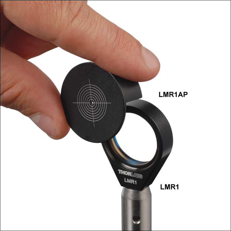
Click to Enlarge
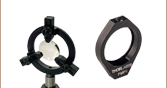
These alignment plates slide over the fixed lens mounts sold above to create a mounted alignment target.
- Quick, Drop-In Visual Beam Alignment Tool
- Ø1 mm Through Hole
- See Table Below for Compatible Fixed Lens Mounts and SM Lens Tubes
These alignment targets can be quickly and easily dropped onto one of our fixed lens holders or lens tubes allowing the user to align a visible beam using the center Ø1 mm through hole. Once the beam is aligned, the tool can be lifted from the lens holder or lens tube without disturbing the alignment and can later be replaced into approximately the same position.
For optimal visual alignment of the beam, these plates feature laser-engraved concentric circles, with the diameter of each circle being 2 mm greater than the previous.
| Alignment Plate Item # | LMR05AP | LMR1AP | LMR30AP | LMR1.5AP | LMR2AP | LMR3AP | LMR4AP |
|---|---|---|---|---|---|---|---|
| Compatible Fixed Lens Mounts | MLH05(/M), LMR05(/M), LMR05V(/M)a, MR05S(/M), SMR05(/M) |
LMR1(/M), LMR1V(/M)a, LMR1S(/M), SMR1(/M) |
LMR30(/M) | LMR1.5(/M) | LMR2(/M), LMR2V(/M)a, LMR2S(/M), SMR2(/M) |
LMR3(/M), LMR75(/M) |
LMR4(/M), LMR100(/M) |
| Compatible SM Lens Tubes | SM05 | SM1 | SM30 | SM1.5 | SM2 | SM3 | - |

 Zoom
Zoom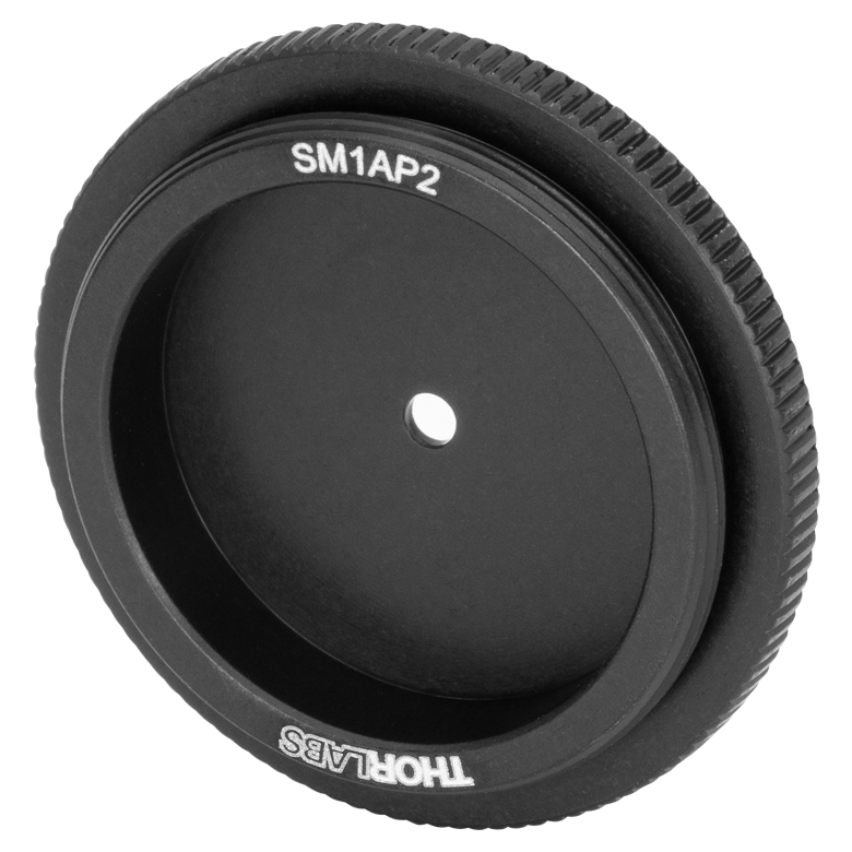
Click to Enlarge
Back View of the SM1AP2 Disk Showing the External SM1 Threads
- SM1AP1: Ø1 mm Through Hole
- SM1AP2: Ø2 mm Through Hole
- External SM1 Threading
- Laser-Engraved Concentric Circles
The SM1AP1 and SM1AP2 alignment disks are useful aids for aligning visible beams to the center of Ø1" lens tubes and other SM1-threaded components. The Ø1 mm and Ø2 mm through holes on the SM1AP1 and SM1AP2 disks, respectively, allow the user to align a visible beam through the center of the disk. For optimal visual alignment of the beam, these disks feature laser-engraved concentric circles from Ø4 mm to Ø20 mm, with the diameter of each circle being 2 mm greater than the previous. The back of each disk features external SM1 (1.035"-40) threading for compatibility with Ø1" lens tubes and other SM1-threaded components. Additionally, the disks feature a knurled edge for secure hand tightening.

 Zoom
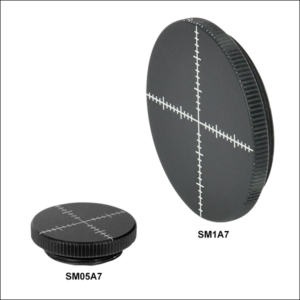
Zoom- Alignment Tick Marks at 1 mm Increments
- External SM05 or SM1 Threading
The SM05A7 and SM1A7 alignment disks provide useful aids for aligning visible beams to the center of optical mounts. To enable accurate alignment, the disks have clear markings with graduations on both the X and Y axes. The back of the SM05A7 features our standard SM05 (0.535"-40) threading for compatibility with Ø1/2" lens tubes and other SM05-threaded components, while the SM1A7 has SM1 (1.035"-40) threading for compatibility with Ø1" lens tubes and other SM1-threaded components.

 Zoom
Zoom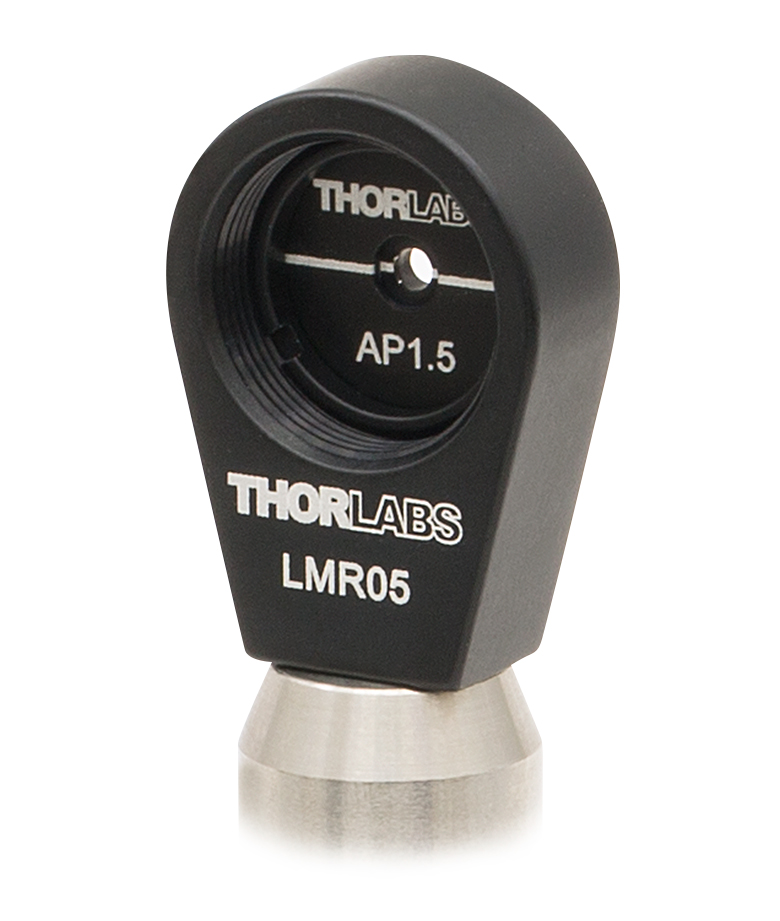
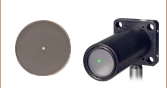
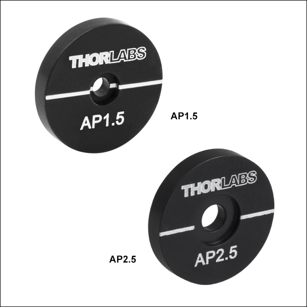
- Mounts in any Ø1/2" Optic Mount
- Ø1.8 mm or Ø2.5 mm Aperture Available
Aperture Plates are a useful tool for system alignment or to measure beam size. The aperture plate should be mounted into a Ø1/2" optic mount (such as the LMR05, as shown in the image to the right) and then can be used to establish an optical center line in a system. It is also useful for blocking stray light or other unwanted light in an optical system.