 Products Home / Fiber Components / Terminal Fiber Components / Fibers and Patch Cables with Lensed Tips
Fibers and Patch Cables with Lensed Tips
- Single Mode or Graded-Index Multimode Fibers with Lensed Tips
- Spot Sizes from Ø5 µm to Ø25 µm
- Available as Bare Fiber or Patch Cables
- Custom Versions Available
LFM100
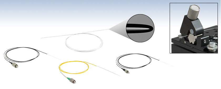
Lensed Tip
Scissor Cut
Application Idea
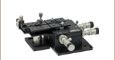
LFM100 Lensed Fiber Mounted in a MBT616D 3-Axis Stage and HFF001 Fiber Clamp for Use in a Fiber Coupling Application
FC/PC Connector
SMA Connector
LFM1F-1
LFM1S-1
Lensed Tip
Lensed Tip
LFS105A1
FC/APC Connector
Lensed Tip


Please Wait
| Key Specificationsa | ||||||
|---|---|---|---|---|---|---|
| Item # Prefix | LFS105 | LFS108 | LFS155 | LFS159 | LFM1 | |
| Fiber Typeb | 1060XP | SMF-28 Ultra | GIF50E | |||
| Wavelength Range | 980 - 1600 nm | 1260 - 1625 nm | 800 - 1600 nm | |||
| Focused Spot Sizec | Ø5.0 ± 0.7 µm | Ø8.0 ± 1.0 µm | Ø5.0 ± 0.5 µm | Ø9.0 ± 1.0 µm | Ø25 µm (Typ.) | |
| Working Distance (Typ.)c | 18.3 µm | 26.5 µm | 22.0 µm | 41.0 µm | 30 µm | |
| Fiber Specificationsd | ||||||
| Numerical Aperture | 0.14 | 0.14 | 0.200 ± 0.015 | |||
| Core Diameter | 5.8 µm | 8.2 µm | 50.0 ± 2.5 µm | |||
| Cladding Diameter | 125 ± 0.5 µm | 125 ± 0.7 µm | 125 ± 1 µm | |||
| Coating Diameter | 245 ± 10 µm | 242 ± 5 µm | 242 ± 5 µm | |||
Click to Enlarge
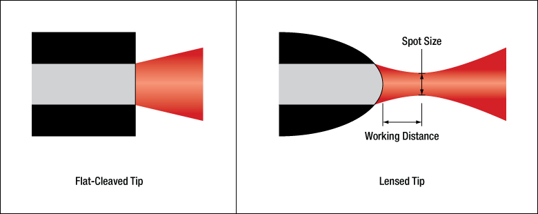
Figure 1.1 Comparison of Beam Output for Flat-Cleaved Tip and Lensed Tip
Features
- Single Mode or Graded-Index Multimode Fiber with Lensed Tip
- Spot Sizes of Ø5.0 µm, Ø8.0 µm, Ø9.0 µm, or Ø25 µm Available
- Available as Bare Fiber or Patch Cables
- Patch Cables are Terminated with FC/PC, FC/APC, or SMA905 Connectors
- Useful for Waveguide and Photodiode Coupling Applications (See the PIC Testing Demo Tab for a Waveguide Coupling Example)
- Manufactured Using Vytran® Fiber Processing Technology
Thorlabs' Lensed Fibers are either a single mode fiber (1060XP or SMF-28 Ultra) or a graded-index multimode fiber (GIF50E) with a convex lensed tip on one end. Unlike light emitted from a flat cleaved fiber tip that diverges immediately, a fiber with a lensed tip will focus the light at a point in front of the tip, as shown in Figure 1.1. Spot sizes of Ø5.0 µm, Ø8.0 µm, Ø9.0 µm, or Ø25 µm with corresponding working distances from 14.8 µm to 49.0 µm are available. More information on simple spot size measurement techniques can be found in the Lensed Fiber App Note. Lensed fibers are useful for applications such as coupling to and from waveguides, active device pigtailing, and waveguide packaging. The photonic integrated circuit (PIC) testing station presented in the PIC Testing Demo tab provides an example of how these lensed fibers can be used to transfer light from an on-chip waveguide to a fiber-based optical system.
These lensed-tip fibers are available from stock as either a 1 m length of bare fiber with one scissor-cut end or as a patch cable. The single mode patch cables have a 2.0 mm narrow key FC/PC or FC/APC connector on one end, while the multimode patch cables have either a 2.0 mm narrow key FC/PC or SMA905 connector on one end. These are jacketed in Ø900 µm Hytrel®* tubing, which is yellow for single mode fibers or black for multimode fibers. The lensed tip is shipped with a protective plastic sleeve to prevent physical damage. Prior to use, the plastic sleeve should be removed and the tip cleaned gently using compressed air or an ultrasonic cleaner.
Lensed fibers are fabricated using Vytran® glass processing technology. Precise heating of the fiber end face provides a high degree of control over the curvature of the lens and thus the focused spot size. Thorlabs is able to leverage our fiber processing experience to create lensed fibers using single mode, multimode, and polarization-maintaining fiber; please contact Tech Sales to inquire about custom lensed fibers for your application.
*Hytrel® is a registered trademark of DuPont Polymers, Inc.
| Single Mode 1060XP Lensed Fiber Specifications | ||||||
|---|---|---|---|---|---|---|
| Item # | LFS105 | LFS105F1 | LFS105A1 | LFS108 | LFS108F1 | LFS108A1 |
| Fiber Termination | Scissor Cut | FC/PC, 2.0 mm Narrow Key |
FC/APC, 2.0 mm Narrow Key |
Scissor Cut | FC/PC, 2.0 mm Narrow Key |
FC/APC, 2.0 mm Narrow Key |
| Fiber Type | 1060XP | |||||
| Wavelength Range | 980 - 1600 nm | |||||
| Insertion Loss | <0.2 dB | |||||
| Focused Spot Sizea | Ø5.0 ± 0.7 µm | Ø8.0 ± 1.0 µm | ||||
| Working Distancea | 18.3 µm (Typ.) | 26.5 µm (Typ.) | ||||
| Fiber Length | 100.0 cm +10 cm/-0 cm | |||||
| Stripped Fiber Lengthb | 2.0 cm ± 0.1 cm | |||||
| Operating Temperature | -55.0 to 85.0 °C | |||||
| Single Mode SMF-28 Ultra Lensed Fiber Specifications | ||||||
|---|---|---|---|---|---|---|
| Item # | LFS155 | LFS155F1 | LFS155A1 | LFS159 | LFS159F1 | LFS159A1 |
| Fiber Termination | Scissor Cut | FC/PC, 2.0 mm Narrow Key |
FC/APC, 2.0 mm Narrow Key |
Scissor Cut | FC/PC, 2.0 mm Narrow Key |
FC/APC, 2.0 mm Narrow Key |
| Fiber Type | SMF-28 Ultra | |||||
| Wavelength Range | 1260 - 1625 nm | |||||
| Insertion Loss | <0.2 dB | |||||
| Focused Spot Sizea | Ø5.0 ± 0.5 µm | Ø9.0 ± 1.0 µm | ||||
| Working Distancea | 22.0 µm (Typ.) | 41.0 µm (Typ.) | ||||
| Fiber Length | 100.0 cm +10 cm/-0 cm | |||||
| Stripped Fiber Lengthb | 2.0 cm ± 0.1 cm | |||||
| Operating Temperature | -60.0 to 85.0 °C | |||||
| Single Mode Fiber Specificationsa | |||
|---|---|---|---|
| Fiberb | |||
| Fiber Typea | 1060XP | SMF-28 Ultra | |
| Wavelength Range | 980 - 1600 nm | 1260 - 1625 nm | |
| Numerical Aperture | 0.14 | 0.14 | |
| Core Diameter | 5.8 µm | 8.2 µm | |
| Cladding Diameter | 125 ± 0.5 µm | 125 ± 0.7 µm | |
| Coating Diameter | 245 ± 10 µm | 242 ± 5 µm | |
| Core-Cladding Concentricity | ≤0.3 µm | <0.5 µm | |
| Coating-Cladding Concentricity | ≤5 µm | ≤12 µm | |
| Attenuation | ≤2.1 dB/km @ 980 nm ≤1.5 dB/km @1600 nm |
≤0.32 dB/km @ 1310 nm ≤0.18 dB/km @1550 nm |
|
| Mode Field Diameter | 5.9 ± 0.5 µm @ 980 nm 6.2 ± 0.5 µm @ 1060 nm 9.5 ± 0.5 µm @ 1550 nm |
9.2 ± 0.4 µm @ 1310 nm 10.4 ± 0.5 µm @ 1550 nm |
|
| Multimode Lensed Tip Specifications | ||
|---|---|---|
| Focused Spot Size | Ø25 µm (Typ.) | |
| Working Distance | 30 µm (Typ.) | |
| Taper Length | 410 µm | |
| Radius of Curvature | 31 ± 1 µm | |
| Insertion Loss | 0.2 dB (Typ.) | |
| Multimode Fiber Specificationsa | ||
|---|---|---|
| Fiberb | ||
| Fiber Typea | GIF50E | |
| Wavelength Range | 800 - 1600 nm | |
| Numerical Aperture | 0.200 ± 0.015 | |
| Core Diameter | 50.0 ± 2.5 µm | |
| Cladding Diameter | 125 ± 1 µm | |
| Coating Diameter | 242 ± 5 µm | |
| Core-Cladding Concentricity | ≤1.5 µm | |
| Coating-Cladding Concentricity | ≤12 µm | |
| Attenuation | ≤2.3 dB/km @ 850 nm ≤0.6 dB/km @1300 nm |
|
| Multimode Physical Specifications | |||
|---|---|---|---|
| Item # | LFM100 | LFM1F-1 | LFM1S-1 |
| Fiber Termination | Scissor Cut | FC/PC, 2.0 mm Narrow Key |
SMA905 |
| Fiber Length | 1 m +0.10 m/-0.0 m | ||
| Stripped Fiber Lengtha | 11 mm ± 1 mm | ||
| Tubing | N/A | Ø900 µm Black Hytrel®b | |
| Length without Tubingc | N/A | 5 ± 1 cm | |
| Operating Temperature | -60 to 85 °C | ||
PIC Demo Testing Station
Thorlabs offers a variety of components that enable construction of a photonic integrated circuit (PIC) testing station, including imaging systems, fiber optics, precision piezos, and manual stages. This page presents a demo system that drives an on-chip laser and collects and analyzes the emitted light. The laser chip employed in this example PIC testing setup is a fully integrated, heterogeneous GaAs-on-SiN platform with an array of tunable lasers, with each source capable of coarsely covering the range from 765 to 795 nm. This PIC chip was supplied by Nexus Photonics. The scheme of this PIC testing demo can be generalized and customized to meet the needs of testing various PIC chips and is not restricted to the specific circuit used here. Click on the highlighted areas in Figure 787B or the links in Table 787A to find descriptions of the subsystems that comprise the demo testing station. Tables 787C and 787D provide a comprehensive list of all parts used in the demo.
| Table 787A PIC Demo Subsystems | |||||
|---|---|---|---|---|---|
| Imaging | Light Collection | PIC Control and Readout | PIC Chip Stage | Probe Card Positioning | General Setup |
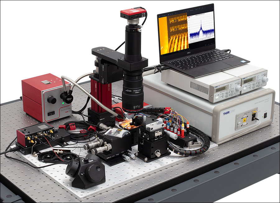
Figure 787B PIC Testing Demo Setup
| Table 787C PIC Demo Parts List | ||
|---|---|---|
| Item #a | Qty. | Description |
| N/A | 1 | PIC Chip (Supplied by Nexus Photonics) |
| Imaging | ||
| SFM2b | 1 | Cerna® Mini Microscope |
| MCM301 | 1 | Three-Channel Stepper Motor Controller for Cerna Components |
| MCMK3 | 1 | 3-Knob USB HID Joystick |
| PLSXY | 1 | 2D Motorized Translation Stage for Rigid Stands |
| PLSZ | 1 | Motorized Module with 1" Travel, 95 mm Dovetail |
| LP126CU(/M) | 1 | Kiralux® Low-Profile 12.3 MP Color CMOS Camera |
| SM2CEFM | 1 | Adapter with External SM2 Threads and Female EF-Mounting Ring |
| CXY1A | 1 | XY Translating Lens Mount for Ø1" Optics |
| N/A | 1 | Canon Macro Lens |
| OSL2 | 1 | High-Intensity Fiber-Coupled Illuminator with Fiber Bundle |
| OSL2YFB | 1 | Gooseneck Y-Bundle for OSL2 and OSL2IR Fiber Light Sources |
| Light Collection | ||
| LFM1F-1 | 1 | FC/PC to Lensed Tip Fiber Patch Cable, Ø50 µm, 0.20 NA |
| TM50R2F1B | 1 | 1x2 Multimode Fiber Optic Coupler, Low OH, Ø50 µm Core, 0.22 NA, 90:10 Split, FC/PC |
| ADAFC3 | 2 | FC/APC to FC/APC Mating Sleeve |
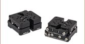
| MAX311D(/M) | 1 | 3-Axis NanoMax™ Stage, Differential Drives, Closed-Loop Piezos |
| PY004(/M) | 1 | High-Load Pitch and Yaw Platform |
| KNA-VIS | 1 | K-Cube® NanoTrak® Active Auto-Alignment Controller, 320 - 1000 nm |
| KPC101 | 1 | K-Cube Piezo Controller and Strain Gauge Reader (Not Shown) |
| KEH3 | 1 | Controller Hub and Power Supply for Three K-Cubes or T-Cubes |
| Table 787D PIC Demo Parts List (Continued) | ||
|---|---|---|
| Item #a | Qty. | Description |
| PIC Control and Readout | ||
| LDC202C | 2 | Benchtop LD Current Controller, ±200 mA HV |
| OSA202C | 1 | Fourier Transform Optical Spectrum Analyzer |
| PIC Chip Stage | ||
| MVS05(/M) | 1 | 1/2" Travel Vertical Translation Stage |
| N/A | 1 | Custom Machined Copper Mount for Chip Stage |
| Probe Card Positioning | ||
| XRV1(/M) | 1 | 14.0 mm Travel Vertical Translation Stage |
| LX20(/M) | 1 | Self-Contained XY 25 mm Translation Stage |
| N/A | 1 | Signatone Probe Card Holder |
| N/A | 1 | Custom Machined Probe Card Adapter |
| General Setup, Organization, and Cable Management | ||
| MB1824Ub | 1 | 18" x 24" Unanodized Aluminum Breadboard |
| CMS015 | 1 | Slit Harness Wrap, 5 m (16.5 ft) |
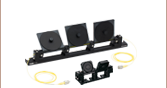
| BFCT | 1 | Passive Component Fiber Tray |
| CSV4 | 1 | Hook-and-Loop-Fastener Cable Straps with Lockdown Rivet (Qty. 5) |
| CS1 | 1 | Screw-On Cable Straps (Qty. 15) |
| B3648FXc | 1 | 36" x 48" Optical Breadboard |
| SDA90120 | 1 | ScienceDesk Frame for 36" x 48" (900 mm x 1200 mm) Tabletops |
Imaging

Click to Enlarge
Figure 787E Image of PIC chip, probes, and collection fiber acquired by the imaging system. The lensed fiber used for light collection can be seen in the lower left of the image. The scale bar shows 1 mm.
A widefield imaging systema is necessary to facilitate alignment of the probe card and light collection (lensed fiber) systems relative to the the PIC chip. Thorlabs' SFM2 Cerna® Mini Microscope provides a simple means to construct an imaging systemb. An LP126CU Kiralux® Scientific Camera attached to the SFM2 Mini Microscope displays the image of the PIC chip, probe card, and collection fiber (shown in Figure 787E). Illumination from a light source like the OSL2 High-Intensity Fiber-Coupled Illuminator can be guided to the chip via the OSL2YFB gooseneck fiber bundle. The combination of an MCM301 Stepper Motor Controller and an MCMK3 USB Joystick with the PLSXY and PLSZ Motorized Translation Stages enables three-dimensional motorized control of the imaging system.
- In this context widefield means an imaging field comparable to the size of the PIC chip.
- An EF-Mount Adapter Ring such as the SM2CEFM can be used to connect the camera lens to the Cerna microscope.


Click to Enlarge
Figure 787F PIC Chip Close Up Showing Probe Card, Collection Fiber, Illumination, and Imaging Microscope
Light Collection
Figure 787F shows a close up of the light collection geometry. Light emitted from the chip is collected by an LFM1F-1 Lensed Multimode Fiber and coupled into an optical spectrum analyzer (as discussed in the previous section). If multiple facets of analysis are desired, the signal can be split using a multimode fiber optic coupler such as the TM50R2F1B. To achieve adequate signal-to-noise ratio, fine positional control of the collection fiber is necessary. Thorlabs offers many components enabling precision control of fiber optics. Thorlabs' NanoMax™ line provides precision fiber positioning, and a PY004 base allows pitch and yaw control. The NanoMax MAX311D contains piezos, which can be controlled for auto-alignment with a combination of the KNA-VIS and KPC101 K-Cube® Controllers. The KEH3 and KEH6 K-Cube controller hubs provide power, Ethernet, and USB connectivity for the K-Cubes.


Click to Enlarge
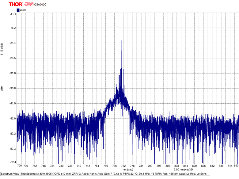
Figure 787G Screenshot of Spectrum Acquired with the OSA202C
PIC Control and Readout
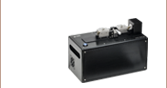
In order to drive the laser circuit on the chip, current is supplied to the PIC chip via the probe card. Two LDC202C Laser Diode Drivers serve as the current sources here. Emitted light collected from the chip is directed into the fiber-coupled OSA202C Optical Spectrum Analyzer, which provides analysis and display of the signal. Figure 787G shows an example screenshot of the spectrum acquired by the OSA202C.
Depending on the particular PIC chip/testing application, various beam characterization and polarization measurement instruments can be used to construct a custom analysis setup to meet specific needs. Examples include the CCT10 Compact CMOS Spectrometer for spectroscopy, the PNA1 Intensity Noise Analyzer for high frequency-axis noise analysis, and the PAX1000IR1 Polarimeter for polarization measurements.
 |
 |
 |
 |
 |
| Laser Diode Drivers | Optical Spectrum Analyzers | Compact CMOS Spectrometers | Intensity Noise Analyzer | Polarimeters |
Positioning


PIC Chip Stage
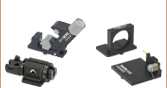
Vertical (Z-axis) control of the PIC chip aids in focusing the widefield imaging system. A vertical drive stage such as the MVS05 Stage provides this additional degree of freedom. If more range is needed, the MVS1 Vertical Translation Stage allows up to 1" of travel.
Probe Card
The probe card serves to supply a multipoint electrical contact directly to the on-chip devices. To achieve optimal/flush contact with the chip multiple degrees of freedom are necessary. A vertical translation stage such as the XRV1 Stage provides vertical translation, and the LX20 Stage allows XY translation.
Thorlabs offers a wide selection of manual stages including linear translation, rotation, and multi-axis stages.
 |
 |
 |
 |
 |
| Optical Tables, Breadboards, and Supports | Solid Aluminum Breadboards | ScienceDesk Workstations | ScienceDesk Shelving | Cable Management |
General Setup, Organization, and Cable Management
Thorlabs offers a wide selection of general components and tools for construction, organization, and management of a PIC testing station. Optical tables, breadboards, and supports provide the foundation of any testing setup. ScienceDesk™ workstations can provide a convenient means to construct a vibration isolated table with a small footprint, and shelving affords convenient options for holding tools, equipment, and instruments. Cable management products for electric and fiber optic cables are also available.
Custom Capabilities
Both the lensed fiber holder and probe card holder were custom made for this specific PIC testing station demo application. Thorlabs offers a wide variety of custom solutions and manufacturing capabilities for various applications. Contact techsales@thorlabs.com for further information.
| Posted Comments: | |
user
(posted 2024-10-07 16:46:05.043) Hi, what are the tolerances for the spot size and working distance for the lensed fibres? Thanks. mgarodia
(posted 2024-10-11 09:33:37.0) Thank you for reaching out to us. We do not have defined tolerances for the spot size and working distance for the lensed tip fibers since they are driven specifications that we do not control or measure, and also because they are dependent on the wavelength and on the launch conditions. I have reached out to you directly to discuss your application and possible alternatives. Angel Ortega
(posted 2022-03-07 05:52:47.977) Hi,
I am looking for a lensed fiber with the FC connector working at 1550 nm, but a monomode one. Do you offer such product? or is it possible to fabricate it?.
Thanks in advance,
Ángel jgreschler
(posted 2022-03-10 09:31:47.0) Thank you for reaching out to Thorlabs. At this time the only fibers Thorlabs provides with lensed tips are multimode items found on this product page. It is possible to fabricate a lensed tip with single mode fibers, I have reached out to you directly to discuss the application further. Gong-Ru Lin
(posted 2020-08-08 02:27:08.28) Do you have this product with other aperture size like 10um or 15um and working distance like 25um or 20um or 15um? Thank you so much for your kind reply as we need these lensed urgently.
Prof. Gong-Ru Lin
National Taiwan University YLohia
(posted 2020-08-10 09:45:41.0) Hello Gong-Ru, thank you for contacting Thorlabs. Custom products can be requested by emailing techsupport@thorlabs.com. I have reached out to you directly to discuss the feasibility of offering this. cheng chen
(posted 2020-05-31 01:01:52.7) what is the chromatic. aberration of this fiber lens ? nbayconich
(posted 2020-06-16 09:15:07.0) Thank you for contacting Thorlabs. We have not modeled the amount of chromatic aberrations created by these lensed fibers. I will reach out to you directly to discuss your application. Georgy Onishchukov
(posted 2020-03-11 15:02:33.72) What is the NA of the focused beam? YLohia
(posted 2020-03-17 02:00:18.0) Hello, due to comparable values for the core diameter, working distance. and focused spot size, measuring the NA is not quite straightforward for this fiber. I have reached out to you directly to discuss this further. |

 Zoom
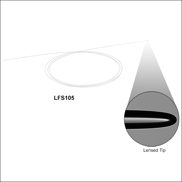
Zoom- 1 m of 1060XP or SMF-28 Ultra Fiber with Lensed Tip
- Spot Sizes of Ø5.0 µm, Ø8.0 µm, or Ø9.0 µm
- 2.0 ± 0.1 cm of Fiber, Stripped to Cladding, on End with Lensed Tip
- Other End is Scissor Cut
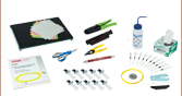
The LFS Series of Single Mode, Lensed-Tip Fibers are available from stock in 1 m lengths. The non-lensed, scissor-cut end can be spliced into a setup if desired, or terminated with a connector using Thorlabs' fiber termination kits.

 Zoom
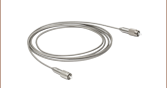
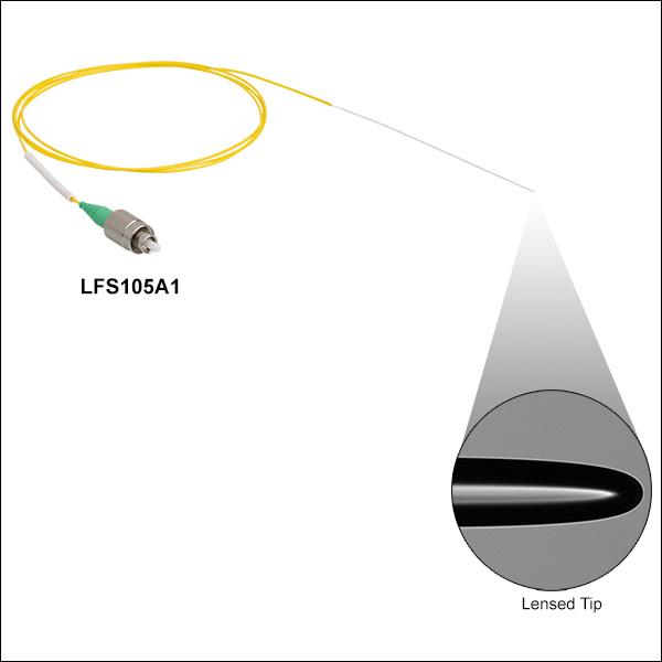
Zoom- 1060XP or SMF-28 Ultra Fiber Patch Cables with Lensed Tip
- 2.0 mm Narrow Key FC/PC or FC/APC Connector
- 1 m Length
- 2.0 ± 0.1 cm of Fiber, Stripped to Cladding, on End with Lensed Tip
- Ø900 µm Yellow Hytrel®* Tubing
These single mode lensed-tip fiber patch cables are offered with either an FC/PC or FC/APC connector on the non-lensed end and Ø900 µm yellow Hytrel® tubing. On the end with the lensed tip, 10 ± 1 cm of the cable is left free of the tubing to expose the inner fiber. The last 2.0 ± 0.1 cm of fiber before the lens is stripped to the cladding.
*Hytrel® is a registered trademark of DuPont Polymers, Inc.

 Zoom
Zoom- 1 m of GIF50E Fiber with Lensed Tip
- 11 ± 1 mm of Fiber, Stripped to Cladding, on End with Lensed Tip
- Other End is Scissor Cut
LFM100 Multimode Lensed-Tip Fiber is available from stock in 1 m lengths. The non-lensed, scissor-cut end can be spliced into a setup if desired, or terminated with a connector using Thorlabs' fiber termination kits.

 Zoom
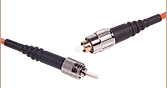
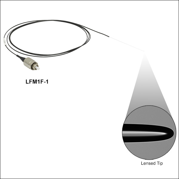
Zoom- GIF50E Fiber Patch Cables with Lensed Tip
- 2.0 mm Narrow Key FC/PC or SMA905 Connector
- 1 m Length
- 11 ± 1 mm of Fiber, Stripped to Cladding, on End with Lensed Tip
- Ø900 µm Black Hytrel®* Tubing
These multimode lensed-tip fiber patch cables are offered with either an FC/PC or SMA905 connector on the non-lensed end and Ø900 µm black Hytrel® tubing. On the end with the lensed tip, 5 ± 1 cm of the cable is left free of the tubing to expose the inner GIF50E fiber. The last 11 ± 1 mm of fiber before the lens is stripped to the cladding.
*Hytrel® is a registered trademark of DuPont Polymers, Inc.