 Products Home / Lab Supplies / Fiber Lab Supplies / Splicers / Fiber Splices and Temporary Termination
Fiber Splices and Temporary Termination

- Reusable Splices Preloaded with Index Matching Gel
- Index Matching Gel Available Separately
- One-Time-Use Splice Protector Sleeves Available
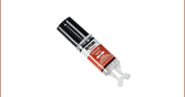
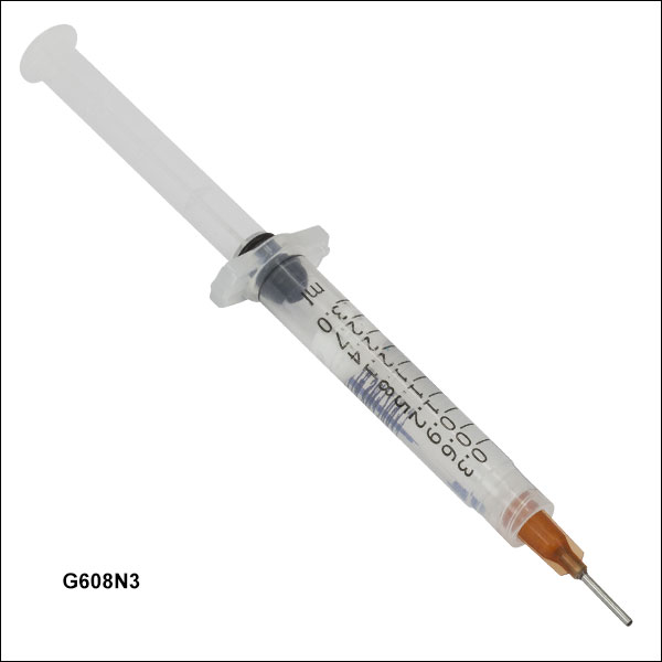
G608N3
Index Matching Gel
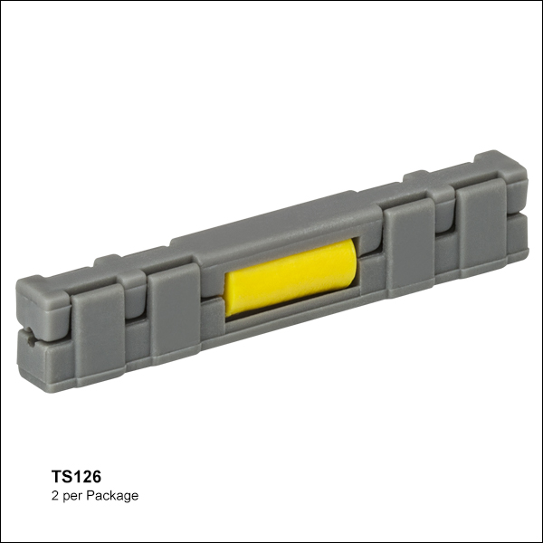
TS126
Fiber Splice, 2 per Package
SPS40
Splice Sleeve Shown with Spliced Fiber
(Fiber Not Included)
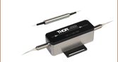
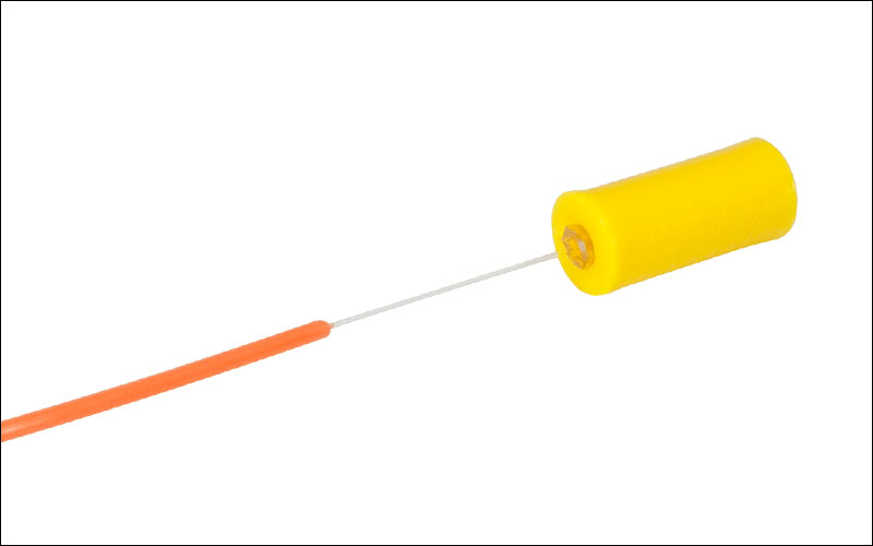
BFT1
Temporary Bare
Fiber Terminator


Please Wait

 Zoom
ZoomFeatures
- Fast Splicing of Fibers
- Self-Gripping Clamshell Design
- Accepts Fibers with Cladding Between Ø125 and Ø140 µm
- Two Mechanical Splices per Package
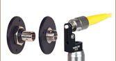
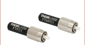
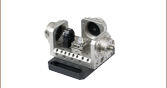
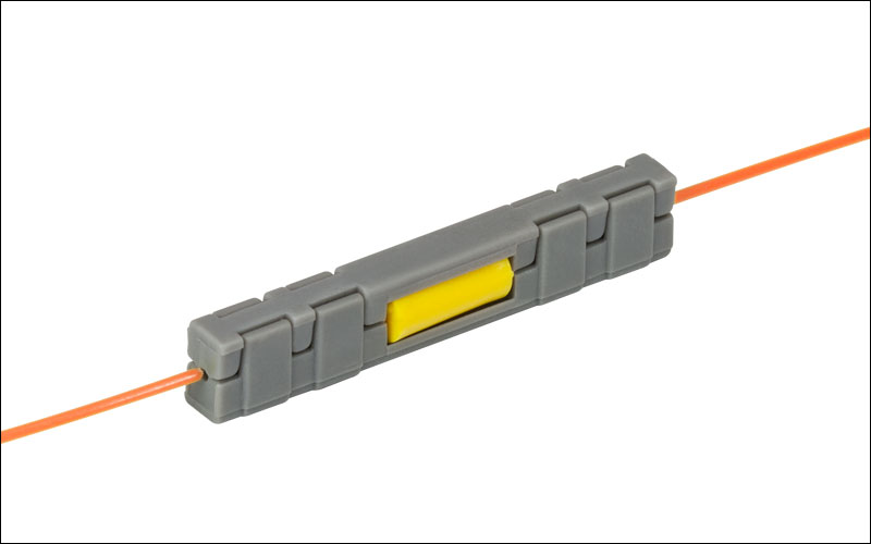
Thorlabs' TS126 reusable, mechanical fiber-to-fiber splices are designed for splicing two single mode or multimode fibers with cladding sizes between Ø125 µm and Ø140 µm. The fiber channels in the gray clamshell casing (see the photo to the right) are divided into two sections with different diameters. The section closest to the yellow fiber splice tube is Ø250 µm to accommodate the fiber coating, while the outer sections are Ø900 µm. Each splice comes preloaded with index matching gel that provides an overall typical splicing loss of 0.2 dB. Additional index matching gel (G608N3 available below) can be applied to the ends of the fibers before inserting them into the yellow splice tube to improve performance when reusing the splice.
Our mechanical fiber-to-fiber splices hold fiber with a self-gripping clamshell design. They are easy to use, providing a quick solution when performing emergency fiber optic splicing. The yellow splice tube can be used alone for a compact package or with the gray clamshell clamp installed for greater stability. For permanent usage, an adhesive (e.g., Super Glue or epoxy) can be injected into the two small through holes in the bottom section of the clamp to achieve a pull strength of 1.5 lbs. See the image above and to the right for details.
For additional fiber termination products, please see our Connector Mating Sleeves, Single Mode Connectors, and Multimode Connectors.
Fiber Splice Assembly
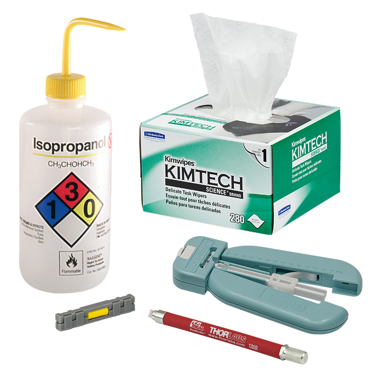
Required Materials
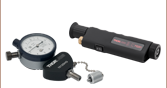
Before beginning a fiber splice, be sure to have the required materials available. This includes the Reusable Fiber-to-Fiber Splice (Item # TS126). Additional needed materials include a fiber stripper, fiber scribe (S90R), 99% pure hospital-grade isopropanol, and Kimwipes®† (KW32). Fibers compatible with this splice unit have cladding sizes between Ø125 µm and Ø140 µm. Therefore, depending on the cladding size, one of these fiber fiber strippers will be needed: T06S13, T08S13, or T08S40. Please visit the links above for additional information about these tools.
†Kimwipes® is a registered trademark of the Kimberly-Clark Corporation.
Assembly
Step 1. Strip, clean, and cleave the two fibers to be spliced. Approximately 14 mm of stripped fiber should be present on each end after cleaving. Complete, step-by-step instructions on how to properly cleave a fiber are found in the Guide to Connectorization and Polishing of Optical Fibers, which is available for download here.
Step 2. Separate the gray plastic "clamshell" pieces from the yellow fiber tube (see Figure 1).
Step 3. Insert one fiber into the small hole at the end of the yellow fiber tube (see Figure 2). When the fiber is securely inside the splice channel, it will start to resist movement.
Step 4. Insert the other fiber into the opposite side of the yellow fiber tube. Couple a light source into one of the fibers and attach the other fiber to a power meter. As the fiber tips approach each other, the transmitted power level will rise until it reaches a maximum as the fiber tips touch (average splicing losses are ~0.2 dB). It may be necessary to gently rotate the fibers to achieve lowest losses. Do not continue to press the fibers together, as this could either break the fibers or result in scratches on the end faces that reduce signal strength.
Step 5. (Optional) Reassemble the gray clamshell pieces for mechanical stability (see Figure 3). Make sure that the fiber is placed into the grove of the clamshell piece as it exits the yellow tube. For a permanent splice and added stability, inject epoxy into the two holes of the larger gray plastic piece.

Click to Enlarge
Figure 1
Click to Enlarge
Figure 2
Click to Enlarge
Figure 3
| Posted Comments: | |
| No Comments Posted |

 Zoom
ZoomFeatures
- Minimize Losses When Mechanically Joining Fibers
- Refractive Index @ 589.3 nm: 1.4646
- Electrically Non-Conductive
- Gel Packaged in 3 cc Syringe
Thorlabs G608N3 is a crystal clear, gel-like, optical coupling compound intended to reduce signal attenuation in wave guide assemblies at connections. The presence of air at the junction of two optical fibers causes significant signal refraction due to the large differential optical impedance that exists between air and the signal-carrying wave guides. The optical coupling compound G608N3 has been formulated with the requisite optical properties of clarity, purity, and refractive index to minimize signal losses while allowing pliable mechanical connections between rigid parts. Unlike a rigid optical epoxy, this pliable gel is viscoelastic and can take up the differential thermal expansion of precision optical parts without inducing excessive stresses or delamination.
In many devices, these materials serve an additional function: they help seal out ambient dust or fluids from sensitive optical components. This gel is formulated to be ultraclean, non-yellowing, and unaffected by x-ray, ultraviolet or sunlight exposure. It has extremely low outgassing and volatility characteristics and is free from light-absorbing microscopic particulates. This optical product is a chemically stable, non-toxic, synthetic material with wide temperature serviceability and is suitable for designs with high reliability and long service life. Each syringe comes with 3 cc of index matching gel. To remove the gel, use acetone or an alcohol such as isopropanol to clean the area of application.
This index matching gel can also be used to eliminate possible air gaps between fibers when mating connectors using a mating sleeve. We also offer a fiber index-matched Light Trap for temporarily coupling light out of a fiber.

| Specifications | ||
|---|---|---|
| Refractive Index | 402 nm | 1.4995 |
| 589.3 nm | 1.4646 | |
| 980 nm | 1.4462 | |
| 1550 nm | 1.4378 | |
| Refractive Index Temperature Coefficient (25 °C to 60 °C) |
-3.5 x 10⁻⁴ per °C | |
| Refractive Index vs. Wavelength (Cauchy Fit)a | 1.4338 + 10520 λ-2 | |
| Optical Absorption (450 - 750 nm) | <0.003% per µm | |
| Apparent Viscosity (25 °C) | 10,600 poises | |
| Oil Separation (24 hrs at 100 °C) | 0.2% | |
| Evaporation (24 hrs at 100 °C) | 1.0% | |
| Specific Gravity (25 °C) | 1.06 | |
| Thermal Coefficient of Expansion | 0.0006 cc/cc/°C | |
| Microscopic Particulate Contamination | 10 - 34 µm | <300 Particles/cc |
| ≥35 µm | 0 Particles/cc | |
| Posted Comments: | |
Larry.Koehler
(posted 2018-10-11 07:49:57.32) MSDS? YLohia
(posted 2018-10-11 09:09:31.0) The MSDS can be accessed by clicking on the red "document" icon on the left side of the part number. Here is a direct link to it: https://www.thorlabs.com/_sd.cfm?fileName=TTN006737-MSDS-en-us.pdf&partNumber=G608N3. dengin
(posted 2016-06-29 07:57:24.373) G608N3
Can we use the index matching gel effectively at 2.0um.
We are want to use the gel in stripping clad light from fibers (Silica).
thank you |

 Zoom
Zoom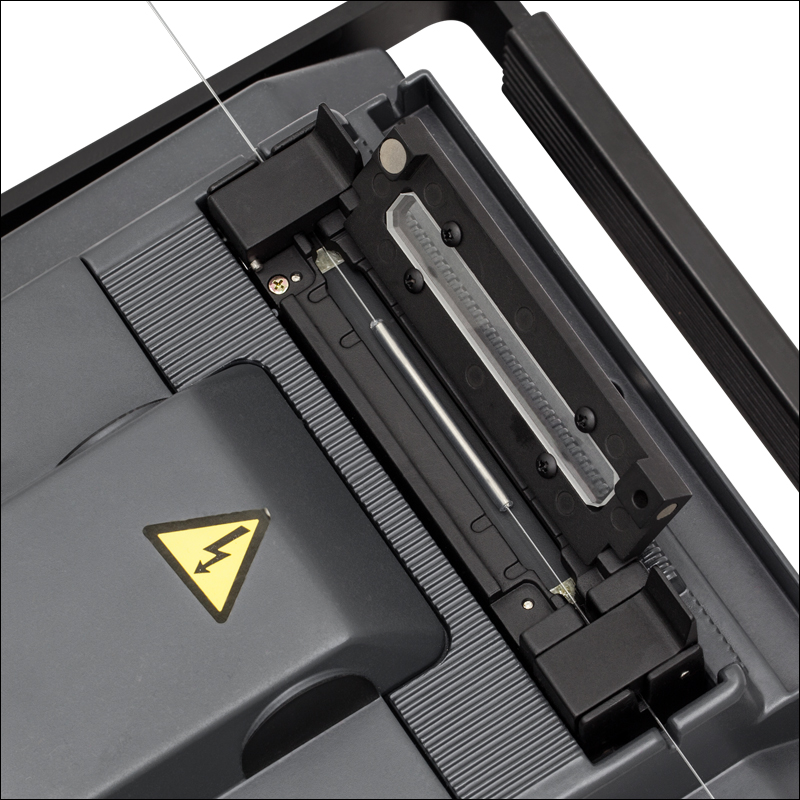
Click to Enlarge
Splice protector sleeve in fiber splicer
Click to Enlarge
Effects of heating on splice protector sleeves.
Features
- Fits Fiber Outer Diameter up to 900 µm
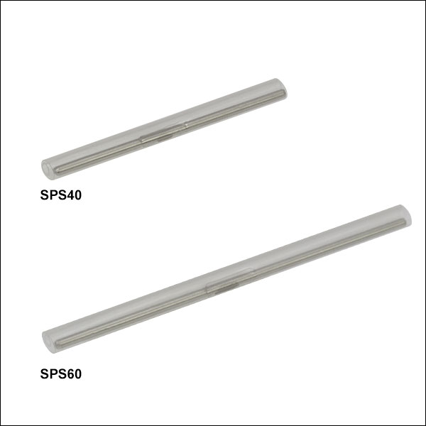
- Available in Either 40 mm or 60 mm Lengths
- Ø3.2 mm After Shrinking
- Sold in Packs of 25
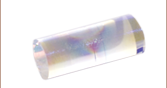
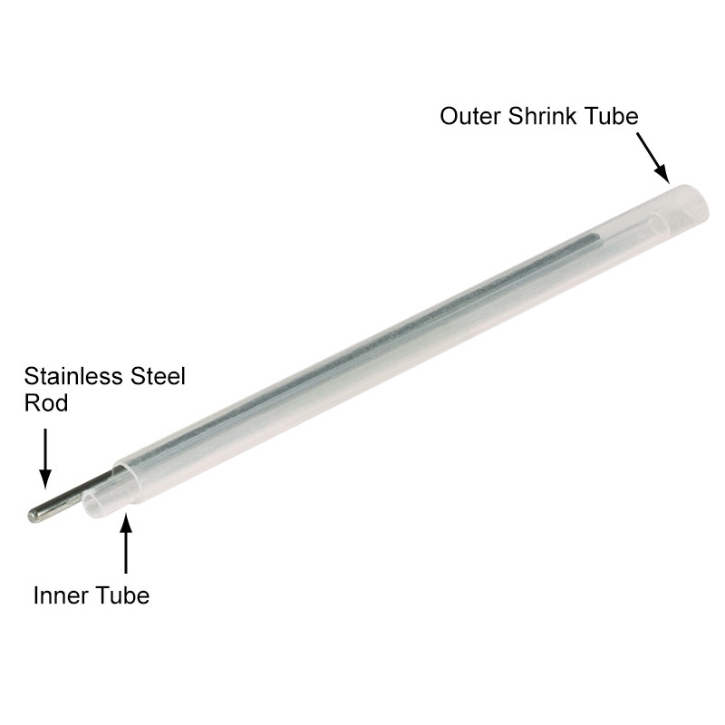
Thorlabs' Splice Protector Sleeves are designed to protect splices in fibers with an outer diameter up to 900 µm. These fusion splice protector sleeves are an economic solution that offers reliable and solid protection for splice joints. An outer shrink tube holds the tube through which the fiber is threaded as well as the strength member, a solid steel rod that provides rigid support for the splice joint. This design not only provides a replacement for the original fiber cable jacket, but also provides excellent rigidity around the splice joint, preventing the spliced area from bending or flexing.
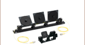
To use, thread the fiber through the inner fiber tube of the sleeve. Position the sleeve so that the splice joint is in the middle. The sleeve must then be heated causing the outer shrink tube to contract to Ø3.2 mm. Proper heating is required to ensure an accurate fit and function of the splice protector sleeve. The image to the left illustrates the effects of proper and improper heating on these sleeves. The top image shows normal heating; here the shrink tube is uniform across the splice, providing permanent and rigid protection. The middle image shows excessive heating; here the shrink tube shows evidence of blemishes and melts in the tubing. The bottom image shows insufficient heating; here the shrink tube is not uniform across the splice, resulting in loose or poor protection for the splice joint. A fiber splicer can be used to ensure proper heating of the sleeve (refer to the operation manual of your splicer for correct heating settings). The image to the right shows a properly heated splice protector sleeve in a fiber splicer (see Splice Sleeve Guide tab for more information).
The clear outer tube of the splice protector sleeves allows the color of the optical fiber itself to be seen. These sleeves come in two standard sizes of 40 mm and 60 mm. They cannot be cut due to the steel rod that provides support for the splice joint. Custom lengths are available; please contact Tech Support for more information.
Thorlabs offers splice-ready connectors, fiber-to-fiber splice kits, fiber cleavers, and stripping & crimping tools for splicing fibers. Alternatively, our Vytran® fiber recoaters offer flexible, low-profile splice protection.
Each splice protector sleeve is composed of an outer shrink tube, an inner tube, and a stainless steel rod to provide rigid support for the splice joint.
| Specification | SPS40 | SPS60 |
|---|---|---|
| Sleeve Length | 40 mm | 60 mm |
| Stainless Steel Rod Length | 35 mm | 55 mm |
| Inner/Outer Tube Material | Ethylene-Vinyl Acetate | |
| Dimension after Shrinking | Ø3.2 mm × 40 mm | Ø3.2 mm × 60 mm |
| Temperature Range after Shrinking | -40 to 80 °C | |

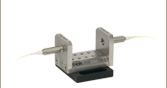
Click to Enlarge
A spliced fiber in a fiber splicer. The splice protector sleeve can be seen in the bottom right of the image. When splicing together two connectorized fibers, thread one of the fibers through the splice protector sleeve before splicing.

Click to Enlarge
A spliced fiber with splice protector sleeve in the heating compartment of a fiber splicer. Once the fiber has been spliced together, slide the protector sleeve over the splice joint and place in the heating compartment of your fiber splicer. Refer to your operation manual to find the correct settings to properly heat the splice protector.
A completed spliced fiber with splice protector sleeve. When correctly applied, the splice protector will hold firmly in position while the stainless steel rod provides rigid support about the splice joint. This will help protect the splice joint as well as prevent any bending or flexing in or around the splice joint.
| Posted Comments: | |
| No Comments Posted |

 Zoom
Zoom
Click for Details
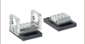
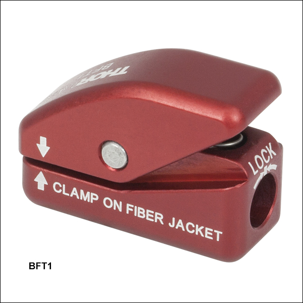
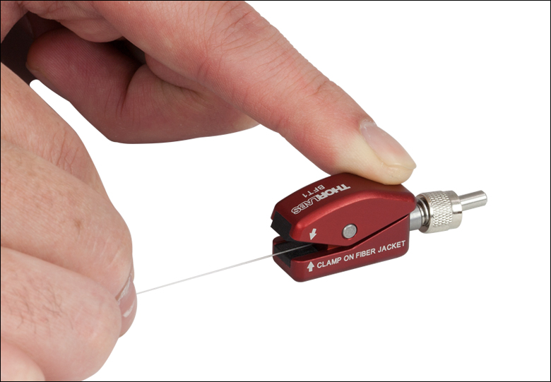
The BFT1 magnetically secures the connector while a bare fiber is held in place using a spring-loaded clamp.
Features
- Bare Fiber Terminator Holds Fiber and Connector without Epoxy
- Compatible Only with BTF1 Fiber Connectors (See the Connectors tab for Details)
- Terminator Accepts Fiber Jacket Diameters from Ø125 µm to Ø1400 µm
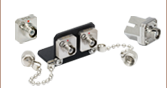
The BFT1 Bare Fiber Terminator is designed to temporarily terminate a bare fiber and is only compatible with the BTF1 connectors (see the Connectors tab for a list of compatible connectors). The connector interface is equipped with a magnet and alignment key to quickly attach and align compatible connectors and can be locked into place with a 0.50" (1.3 mm) hex key. Bare fiber from Ø125 µm to Ø1400 µm can be secured using a spring-loaded clamp (indicated by the engraving in the image to the left) equipped with rubber grips to minimize stress on the fiber. For step-by-step instruction on how to terminate a fiber using the BFT1, please see the Usage Tips tab.
For our full web presentation of the BFT1 and compatible connectors, please click here.
The tables below list the connectors that are only compatible with the BFT1 bare fiber terminator.
| Other Multimode Connectors for the BFT1 | ||
|---|---|---|
| Item # | Style | Bore |
| B30128C3 | FC/PC Ceramic Ferrule |
127 +5/-0 µm |
| B30140E1 | 140 +2/-0 µm | |
| B30230C | 230 +10/-0 µm | |
| B30250C | 250 +10/-0 µm | |
| B30340C | 340 +10/-0 µm | |
| B30440C | 440 +10/-0 µm | |
| B30500C | 500 +10/-0 µm | |
| B30126G2-640 | FC/PC SS Ferrule |
640 +20/-5 µm |
| B30126G2-670 | 670 +20/-5 µm | |
| B30126G2-850 | 850 +30/-10 µm | |
| B30126G2-1050 | 1050 +30/-10 µm | |
| B10127C | ST®/PC | 127 +4/-0 µm |
| SMA905 Multimode Connectors for the BFT1 | ||
|---|---|---|
| Item # | Style | Bore |
| B10125A | SMA905 SS Ferrule |
128 +5/-0 µm |
| B10140A | 144 +5/-0 µm | |
| B10230A | 231 +10/-0 µm | |
| B10250A | 250 +15/-0 µm | |
| B10340A | 340 +15/-0 µm | |
| B10410A | 410 +15/-0 µm | |
| B10440A | 440 +15/-0 µm | |
| B10510A | 510 +15/-0 µm | |
| B10610A | 612 +15/-0 µm | |
| B10640A | 641 +15/-0 µm | |
| B10770A | 770 +15/-0 µm | |
| B10850A | 850 +15/-0 µm | |
| B11040A | 1040 +15/-0 µm | |
| B11050A | 1050 +15/-0 µm | |

Click to Enlarge
Step 2: Feed Fiber Through the Connector

Click for Details
BFT-FSSMA Fiber Stop with the BFT1 and B10125A Connector
Click to Enlarge
Step 4: Align Fiber Tip with Ferrule End
Click to Enlarge
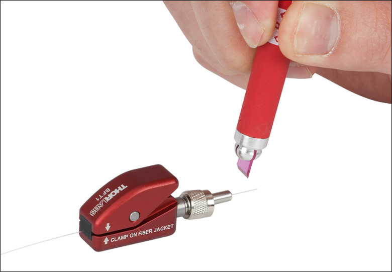
Step 3: Cleave Fiber
This tab contains step-by-step instructions on terminating a bare fiber using the BFT1 bare fiber terminator. The items in the images to the right are the BFT1, B10125A (Ø125 µm, multimode SMA905 connector), S90R fiber scribe, and BFT-FSSMA SMA905 fiber stop. These instructions are also engraved on the bottom surface of the BFT1. The animation to the right below illustrates the step-by-step usage of the BFT1.
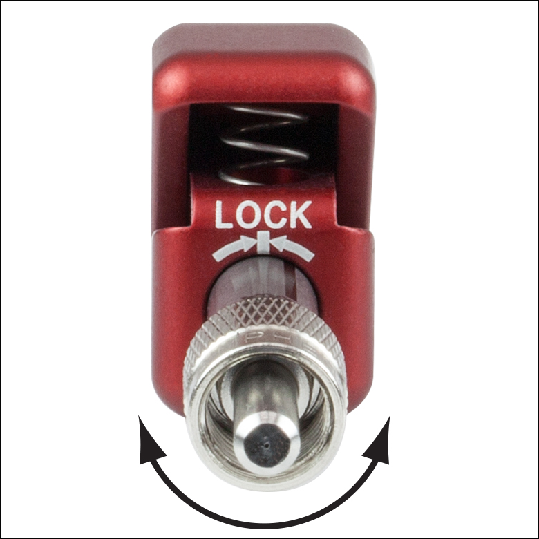
Step 1: Insert the Ø0.22" (Ø5.5 mm) metal sleeve end of the connector into the BFT1. Rotate the connector within the hole of the BFT1 until the key and connector align; the connector should now be magnetically secured. For additional support, the connector can be locked in place by tightening the setscrew on the side of the BFT1 using a 0.05" (1.3 mm) hex key.
Step 2: Strip the fiber; for additional instructions on stripping and cleaning optical fiber, please see our FN96A connectorization guide.
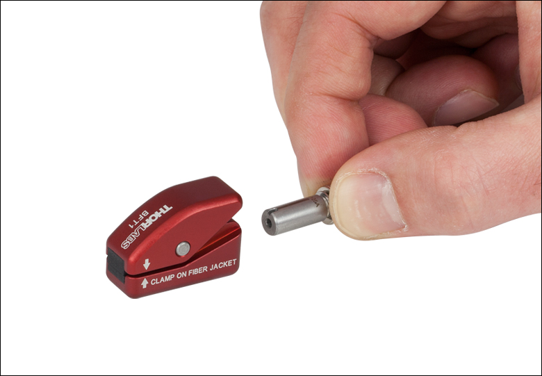
Step 3: Use a manual cleaver (Item # CLV150) or fiber scribe (Item # S90R) to cleave the fiber, following the instructions provided with your cleaver or scribe. After this, use a finger to break the fiber at the cleave point. Alternatively, tape the cleaved end of the fiber to a table and then gently pull on the fiber from the back side of the BFT1 to break it at the cleaving point.Then, while pressing the spring-activated lever, slowly feed the fiber through the BFT1 from the clamp side until the fiber passes through both the BFT1 and the connector ferrule. Release the clamp to secure the fiber in position. Because debris can accumulate on the rubber grips of the clamp, which in some cases can cause fiber damage, we recommend clamping the fiber jacket rather than bare glass.
Step 4: Finally, while pressing the lever, gently pull the fiber back until the tip of the fiber is flush with the ferrule end. Release the lever in order to secure the fiber in position. Thorlabs does not recommend polishing the fiber while secured within the BFT1 as the fiber may be misaligned during the process.
If precise alignment is required, the BFT-FSSMA or BFT-FSFC fiber stops can aid with the fiber alignment in step 4. For this process, pull the fiber until the fiber tip is inside the ferrule. Attach the appropriate fiber stop to the other end of the connector (as shown in the image to the right) and then gently push the fiber until the tip contacts the ferrule inside the fiber stop. At this point, release the lever to lock the fiber in position and then remove the fiber stop. Please note that spring-loaded ferrules may compress slightly and that fiber tip alignment may depend on the ferrule compression.
| Posted Comments: | |
tomjspot-thor
(posted 2014-03-28 10:11:06.46) I was wondering if the Bare Fiber Terminator is used the same way one would make an regular connector just without the epoxy. In particular does one also have to polish the fiber after cleaving? pbui
(posted 2014-04-02 04:48:34.0) First, you would need to strip and cleave the fiber before inserting the fiber into the connector. Then, you visually align the fiber tip with the ferrule hole before clamping down with the BFTU. If you're working with < 500 um core fibers, if the cleave is good, then there's no need to polish. With larger core sizes, you may need to hand polish it. briana.singleton
(posted 2013-11-22 12:27:33.317) Can you please give the material that the BFTU is composed from? I would like to use it in a radiation environment and need to know how it will respond. Thanks. pbui
(posted 2013-11-27 03:36:39.0) Response from Phong at Thorlabs: The BFTU is composed primarily of various grades of Aluminum. Additional internal components include metal springs and dowels. user
(posted 2013-06-27 10:15:54.26) BFTU
The bare fiber connector is useful tool, yet it need s improvement. It presses the fiber bit too hard, so it disturbed the mode. When using with single mode bare fiber, it works OK. However I use Bessel beam and I can see immediately the beam intensity changes to elliptically asymmetric profile after releasing the locker. pbui
(posted 2013-08-05 11:26:00.0) Response from Phong at Thorlabs: Thank you for your feedback. I'm sorry to hear that the BFTU is altering your Bessel Beam's profile. Unfortunately, this is inherent to the design of the BFTU in order to make it universal, since the clamping force is required to secure the fiber in place. We are looking into other designs that don't require as much clamping force so as to reduce the effect it has on the beam's profile. oscar
(posted 2013-02-07 13:01:38.957) Dear Sir/Madam,
Dear Sir/Madam,
I would like to confirm if the BFU module is compatible with the use of 30126G2-1050 connectors. If not, I also would like to know how to use these connectors in a reusable way.
thank you very much for your kind help.
Sincerely
Dr. Oscar Esteban
Alcala University (Spain) tcohen
(posted 2013-02-21 15:06:00.0) Response from Tim at Thorlabs: The diameter of fiber that your connector would accept is too large for the BFTU. We are currently working to expand the compatibility with different connectors and buffer sizes and I will contact you to discuss this with you further. bdada
(posted 2011-10-11 14:58:00.0) Response from Buki at Thorlabs:
Thank you for your feedback on our web presentation. We will work on making the information clearer so it is easier to tell which connectors can be used with the BFTU fiber terminator. Please contact TechSupport@thorlabs.com if you have any questions. user
(posted 2011-10-11 11:05:53.0) For the specs of part number BFTU, I think it would be more clear to state which adapters DO work with BFTU in addition to which adapters are not compatible. It's a little bit confusing trying to figure out how to choose the correct adapter for various uses. |