 Products Home / Actuators, Adjusters, & Transducers / Piezoelectric Chips and Stacks / Low-Voltage Piezoelectric Chips, 0.7 µm to 6.1 µm Travel
Low-Voltage Piezoelectric Chips, 0.7 µm to 6.1 µm Travel
- Low-Voltage Piezo Chips with 45 V, 75 V, 100 V, or 150 V Max Voltage
- Sub-Millisecond Response Time with No Load
- Provided with or without Pre-Attached Wires
- Operating Temperatures Up to 130 °C (PZT) or 250 °C (BSPT)
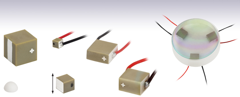
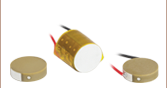
PA4DG
Bare Electrode (2 Places),
Arrow Indicates
Direction of Expansion,
PZT
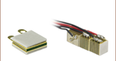
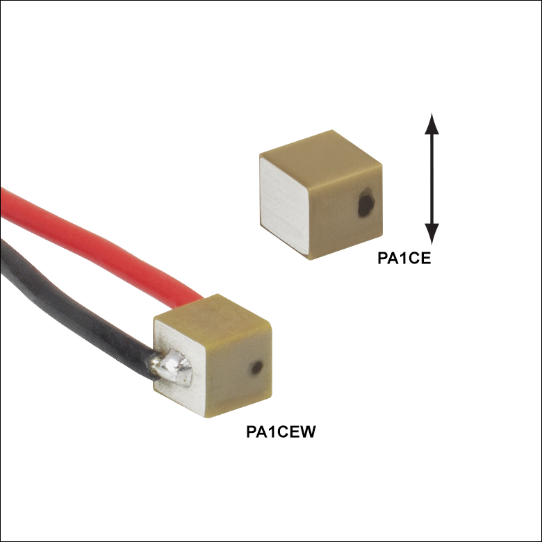
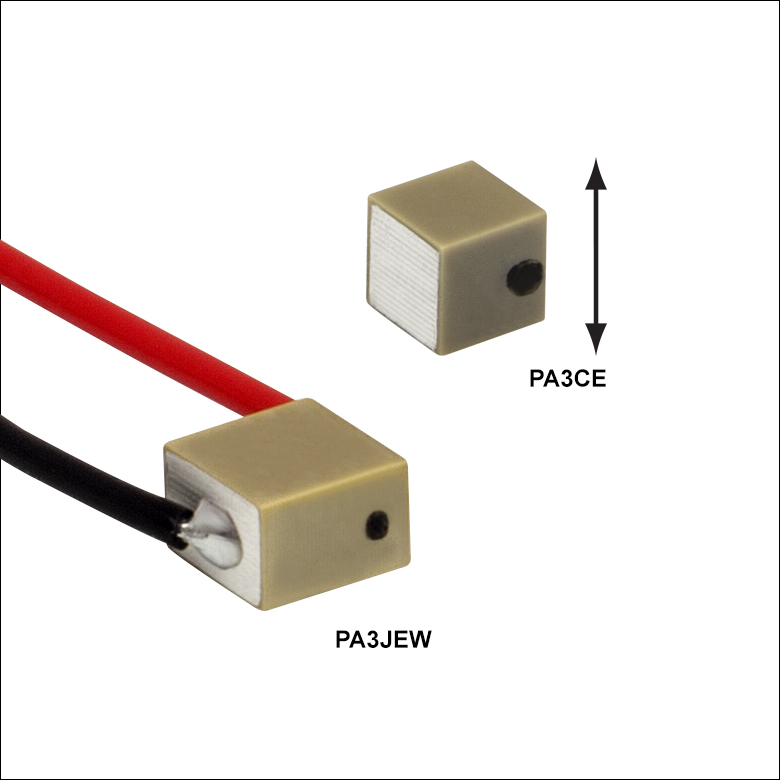
PA3CEW
75 mm Wires, Black Dot Indicates Positive Electrode, PZT
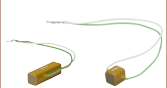
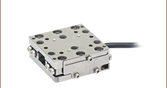
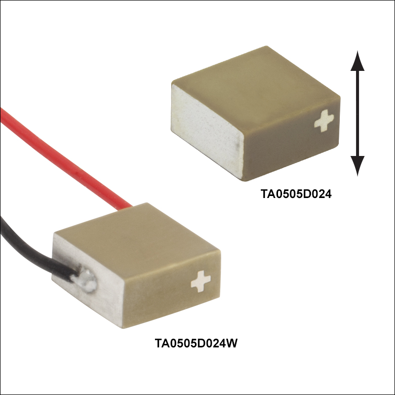
TA0505D024W
75 mm Wires,
Silver Plus Sign Indicates Positive Electrode, PZT
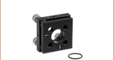
Application Idea
Piezo Chips Tune the Position
of a Ø1" Mirror in a Laser Cavity
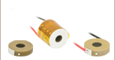
PKDESP
End Hemisphere
PA4FL
Bare Narrow Electrode
(2 Places), PZT
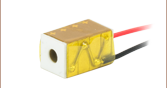
PA4FKYW
75 mm Wires, Silver Plus Sign Indicates Positive Electrode, BSPT


Please Wait
| Piezo Selection Guide |
|---|
| Piezoelectric Ceramic Chips |
| Square |
| Square with Through Hole |
| Round |
| Ring |
| Tube |
| Shear |
| Benders |
| Single-Crystal Piezoelectric Chips |
| Square |
| Piezoelectric Stacks |
| Mounted Piezoelectric Actuators |
| Ultrasonic Piezo Chips & Transducers |
| Vibrating Piezo Actuator |
Click to Enlarge
Three-Dimensional Cross Section of Multilayer Piezo with Interdigitated Electrodes (Item # TA0505D024 Shown); Dashed Lines Indicate Cutaway
| Webpage Features | |
|---|---|
| Clicking this icon below will open a window that contains specifications, mechanical drawings, and graphs. | |

Features
- Sub-Micron Resolution
- Mounting Face Dimensions from 0.9 mm x 0.9 mm to 10.0 mm x 10.0 mm
- Custom Options Available by Contacting Tech Support
- Drive Voltage Range of 0 - 45 V, 0 - 75 V, 0 - 100 V, or 0 - 150 V
- Recommended Loads from 13 N (3 lbs) to 1600 N (360 lbs)
- Maximum Operating Temperature of 130 °C for Lead Zirconate Titanate (PZT) Chips
- BiScO3-PbTiO3 (BSPT) Chips Offered for Temperatures Up to 250 °C
- For Use in Open-Loop Setups
- Many Chips Available with Pre-Attached Wires
- Ideal for Vacuum and OEM Applications
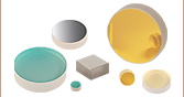
- End Hemispheres and Flat End Plates also Available Separately
Thorlabs' piezoelectric actuators are fabricated from layered sheets of piezoelectric ceramic as is shown in the diagram at upper right and described in the Thorlabs' In-House Piezoelectric Manufacturing box below. Electrodes are printed on each sheet before they are layered, and a precision lapping process ensures the height tolerance of each chip is better than ±5 µm. The compact multilayer design results in chips with high resonant frequencies (160 kHz - 1350 kHz) and sub-millisecond response times. Chips made from both PZT and BSPT piezoelectric ceramic are available, with operating temperatures up to 130 °C for PZT chips and 250 °C for BSPT chips.
These actuators are characterized by precision movement and produce free stroke (unloaded conditions) displacements from 0.7 µm to 6.1 µm. The maximum displacement of these actuators is achieved when they are preloaded with the maximum displacement load, which is specified for each product. The actual value of the maximum displacement varies for each item and must be experimentally determined; however, the maximum displacement will always be larger than the free stroke displacement. Please see the Operation tab for additional information.
Electrodes are included on each layer of the chip, as this minimizes the voltage required to drive them. Our piezoelectric chips are available with one of four drive voltage ranges: 0 - 45 V, 0 - 75 V, 0 - 100 V, or 0 - 150 V. When your application is highly sensitive to voltage, consider our chips with maximum drive voltages of 45 V or 75 V. For applications that are less sensitive, the 100 V and 150 V options have longer lifetimes. For a complete list of specifications, see the tables below.
The areas of these chips without electrodes are coated with a ceramic layer that acts as a barrier against moisture. The ceramic layer offers better protection against moisture than an epoxy coating. Screen-printed silver electrodes are printed on the chip, to which the drive voltage is applied. The positive side will be denoted with either a silver "+" or by a black dot. For convenience, many of our products ship with 75 mm wires soldered to these two sides.
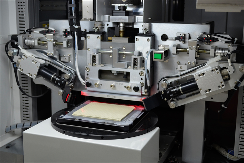
Thorlabs' piezoelectric chips are individually inspected using a proprietary AI algorithm to ensure the highest quality of our line of piezo chips, actuators, and transducers.
To accommodate a variety of loading conditions, flat ceramic or hemispherical ceramic endplates may be purchased as accessories for these chips. In addition, Thorlabs offers conical end cups, which are compatible with ball contacts possessing diameters between 1.5 mm to 7.0 mm. Please see the Operation tab for information on interfacing piezoelectric actuators with loads, special operational considerations, and data that will allow the lifetimes of these actuators to be estimated when their operational conditions are known.
Piezoelectric chips with custom dimensions, voltage ranges, and coatings are available. Additionally, we support high-volume orders. Please contact Tech Support for more information.
Click to Enlarge
Dicing a PZT Block into Individual Elements

Click to Enlarge
Chips After Binder Burnout and Sintering
Thorlabs' In-House Piezoelectric Manufacturing
Our piezoelectric chips are fabricated in our production facility in China, giving us full control over each step of the manufacturing process. This allows us to economically produce high-quality products, including custom and OEM devices. A glimpse into the fabrication of our piezoelectric chips follows. For more information about our manufacturing process and capabilities, please see our Piezoelectric Capabilities page.
- Build Blocks from Flexible Sheets of Lead Zirconate Titanate (PZT) or BiScO3-PbTiO3 (BSPT) Powder
- Screen Print Electrodes on Each Individual Sheet
- Layer the Printed Sheets One Top of Another
- Consolidate the Layered Sheets in an Isostatic Press
- Dice the Block into Individual Elements
- Purge Solvent and Binder Material Residues by Heat Treating the Elements
- Sinter the Elements to Fuse the Piezoelectric Pressed Powder and Grow PZT or BSPT Crystals
- Lap the Elements to Achieve Tight Dimensional Tolerances: ±5 µm for Each Element
- Screen Print the Outer Electrodes on the Elements
- Align the Individual PZT or BSPT Crystals Along the Same Axis by Poling the Elements

Click to Enlarge
Schematic of TA0505D024W Piezo Chip
Operation Notes
Power Connections
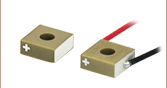
A positive bias should be applied across the device. The positive electrode should receive positive bias, and the other electrode should be connected to ground. Applying a negative bias across the device may cause mechanical failure. For products that ship with wires attached, the positive wire may be identified in two ways: it is red, as can be seen in the product images, and it is attached to the electrode on the side of the chip indicated by a + mark, as is depicted in the image at right. (On some devices, the + mark is replaced by a dot.) The wire that should be grounded is black, and it is attached to the electrode on the side of the chip opposite the side with the positive electrode.
Caution: After driving, the piezo is fully charged. Directly connecting the positive and negative electrodes has the risk of electricity discharging, spark, and even failure. We recommend using a resistor (>1 kΩ) between the electrodes to release the charge.
Preloading
The maximum displacement of these actuators is achieved when they are preloaded with the maximum displacement load, which is specified for each product. The actual value of the maximum displacement varies for each item and must be experimentally determined; however, the maximum displacement will always be larger than the free stroke displacement. Preloading increases the length of the actuator's stroke because the poling process performed during fabrication does not align all ferroelectric grains in the piezoelectric material in the same direction. Preloading the actuator mechanically forces many of the mis-aligned grains into a more ideal alignment. Applying a driving voltage across the piezo material causes the orientations of the ferroelectric grains to rotate so they become aligned with the applied field, and this results in a dimensional change of the piezo material. When more ferroelectric grains are initially aligned in the same direction, the dimensional change of the piezo material in response to the applied driving voltage is greater. Preloads greater than the optimal maximum displacement load result in displacements less than the maximum displacement, as higher loads oppose the switching of the grain orientations in response to the applied driving voltage.
Soldering Wire Leads to the Electrodes
If wire leads must be attached or reattached to the electrodes, a soldering temperature no higher than 370 °C (700 °F) should be used, and heat should be applied to each electrode for a maximum of 2 seconds. Solder the lead to the middle of the electrode and keep the region over which heat is applied as small as possible.
Interfacing a Piezoelectric Element with a Load
Piezoceramics are brittle and have low tensile strength. Avoid loading conditions that subject the actuator to lateral, transverse, or bending forces. When applied incorrectly, an external load that may appear to be compressive can, through bending moments, cause high tensile stresses within the piezoelectric device. Improperly mounting a load to the piezoelectric actuator can easily result in internal stresses that will damage the actuator. To avoid this, the piezoelectric actuator should be interfaced with an external load such that the induced force is directed along the actuator's axis of displacement. The load should be centered on and applied uniformly over as much of the actuator's mounting surface as possible. When interfacing the flat surface of a load with an actuator capped with a flat mounting surface, ensure the two surfaces are highly flat and smooth and that there is good parallelism between the two when they are mated. If the external load is directed at an angle to the actuator's axis of displacement, use an actuator fitted with a hemispherical end plate or a flexure joint to achieve safe loading of the piezoelectric element.
To accommodate a variety of loading conditions, flat ceramic or hemispherical ceramic end plates may be purchased as accessories for these chips. In addition, Thorlabs offers Conical End Cups which feature concave surfaces that can interface with Ø1.5 mm to Ø7.0 mm hemispherical or curved contacts. To attach a load to PZT piezo chips, we recommend using an epoxy that cures at a temperature lower than 80 °C (176 °F), such as our 353NDPK or TS10 epoxies or Loctite® Hysol® 9340. For BSPT piezo chips, we recommend any inorganic adhesive which cures at a temperature lower than 120 °C and has a melting point higher than 250 °C; our 353NDPK epoxy is safe to use, however the strength will be reduced at 250 °C, and therefore a preload should be applied to maintain the mechanical structure. Loads should be mounted only to the faces of the piezoelectric chip that translate. Mounting a load to a non-translating face may lead to the mechanical failure of the actuator. Some correct and incorrect approaches to interfacing loads with piezoelectric actuators capped with both kinds of end plates are discussed in the following.

Click to Enlarge
Actuation of a lever arm using a piezo element fitted with a flat plate (A, Incorrect), and a hemispherical plate (B, Correct).
Click to Enlarge
Loads properly and improperly mounted to piezo actuators using a variety of interfacing methods.
The image at left presents incorrect (A, far-left) and correct (B, near-left) methods for using a piezoelectric element to actuate a lever arm. The correct method uses a hemispherical end plate so that, regardless of the angle of the lever arm, the force exerted is always directed along the translational axis of the actuator. The incorrect interfacing of the element and the lever arm, shown at far-left, endangers the piezo element by applying the full force of the load to one edge of the element. This uneven loading causes dangerous stresses in the actuator, including a bending moment around the base.
The image at right shows one incorrect (near-right, A) and three correct approaches for interfacing a flat-bottomed, off-axis load with a piezoelectric actuator. Approaches A and B are similar to the incorrect and correct approaches, respectively, shown in the image at left. Correct approach C shows a conical end cup, such as the PKFCUP, acting as an interface. The flat surface is affixed to the mating surface of the load, and the concave surface fits over the hemispherical dome of the end plate. In the case of correct approach D, a flexure mount acts as an interface between the off-axis flat mounting surface of the load and the flat mounting plate of the actuator. The flexure mount ensures that the load is both uniformly distributed over the surface plate of the actuator and that the loading force is directed along the translational axis of the actuator.
Operating Under High-Frequency Dynamic Conditions
It may be necessary to implement an external temperature-control system to cool the device when it is operated at high frequencies. The maximum operating temperature of the PZT piezo devices is 130 °C (266 °F), and high-frequency operation causes the internal temperature of the piezoelectric device to rise. For higher temperature applications, BSPT piezo devices are available with a maximum operating temperature of 250 °C. The dependence of the device temperature on the drive voltage frequency for each product can be accessed by clicking the Info icons, ![]() , below. The temperature of the device should not be allowed to exceed its specified maximum operating temperature.
, below. The temperature of the device should not be allowed to exceed its specified maximum operating temperature.
Estimating the Resonant Frequency for a Given Applied Load
A parameter of significance to many applications is the rate at which the piezoelectric actuator changes its length. This dimensional rate of change depends on a number of factors, including the actuator's resonant frequency, the absolute maximum bandwidth of the driver, the maximum current the piezoelectric device can produce, the capacitance of the piezoelectric actuator, and the amplitude of the driving signal. The length of the voltage-induced extension is a function of the amplitude of the applied voltage driving the actuator and the length of the piezoelectric device. The higher the capacitance, the slower the dimensional change of the actuator.
Quick changes in the applied voltage result in fast dimensional changes to the piezoelectric chip. The magnitude of the applied voltage determines the nominal extension of the chip. Assuming the driving voltage signal resembles a step function, the minimum time, Tmin, required for the length of the actuator to transition between its initial and final values is approximately 1/3 the period of resonant frequency. If there is no load applied to the piezoelectric actuator, its resonant frequency is ƒo and its minimum response time is:

After reaching this nominal extension, there will follow a damped oscillation in the length of the actuator around this position. Controls can be implemented to mitigate this oscillation, but doing so may slow the response of the actuator.
Applying a load to the actuator will reduce the resonant frequency of the piezoelectric chip. Given the unloaded resonant frequency of the actuator, the mass of the chip, m, and the mass of the load, M, the loaded resonant frequency (ƒo') may be estimated:
Estimating Device Lifetime for DC Drive Voltage Conditions
The lifetime of a piezoelectric device is a function of the operating temperature, applied voltage, and relative humidity conditions. Lifetimes are reduced as a consequence of humidity-driven electrolytic reactions, which occur at the electrodes of the piezoelectric devices when a DC voltage is applied. These reactions both generate hydrogen and result in metal dendrites growing from the cathode towards the anode. The hydrogen liberated by the electrolytic reaction chemically reacts with and degrades the piezoelectric material. Dendrites that grow to electrically connect the cathode and anode result in increasing levels of leakage current. Failed piezoelectric devices are defined as those that exhibit leakage current levels above an established threshold.
A ceramic moisture-barrier layer that insulates Thorlabs' piezoelectric devices on four sides is effective in minimizing the effects of humidity on device lifetime. As there is interest in estimating the lifetime of piezoelectric devices, Thorlabs conducted environmental testing on our ceramic-insulated, low-voltage, piezoelectric actuators. The resulting data were used to create a simple model that estimates the mean time to failure (MTTF), in hours, when the operating conditions of humidity, temperature, and applied voltage are known. The estimated MTTF is calculated by multiplying together three factors that correspond, respectively, to the operational temperature, relative humidity, and fractional voltage of the device. The fractional voltage is calculated by dividing the operational voltage by the maximum specified drive voltage for the device. The factors for each parameter can be read from the following plots, or they may be calculated by downloading the plotted data values and interpolating as appropriate.
In the following trio of plots, the solid-line segment of each curve represents the range of conditions over which Thorlabs performed testing. These are the conditions observed to be of most relevance to our customers. The dotted-line extensions to the solid-line segments represent extrapolated data and represent a wider range of conditions that may be encountered while operating the devices.
Click to Enlarge
For an Excel file containing these fH vs. relative humidity data, please click here.
The data used to generate these temperature, voltage, and humidity factor plots resulted from the analysis of measurements obtained from testing devices under six different operational conditions. Different dedicated sets of ten devices were tested under each condition, with each condition representing a different combination of operational voltage, device temperature, and relative humidity. After devices exhibit leakage current levels above a threshold of 100 nA, they are registered as having failed. The individual contributions of temperature, humidity, and voltage to the lifetime are determined by assuming:
- MTTF = fV(V) * fT(T) * fH(H)
- A power law dependence for the voltage: fV(V) = A1Vb1
- An exponential relationship for the relative humidity: fH(T) = A2ecH
- An Arrhenius relationship for the temperature: fT(H) = A3eb2/T
where A1, A2, A3, b1, b2, and c are constants determined through analysis of the measurement data, V is the DC operational voltage, T is the device temperature, and H is the relative humidity. Because the MTTF has a different mathematical relationship with each factor, the dependence of the MTTF on each factor alone may be determined. These are the data plotted above. The regions of the above curves marked by the blue shading are derived from experimental data. The dotted regions of the curves are extrapolated.
Lifetime testing of these devices continues, and additional data will be published here as they become available. To assist in temperature control, please see our selection of thermoelectric coolers. Temperature and humidity can be monitored using our USB Temperature and Humidity Logger.
Cleaning for Vacuum Compatibility
When suitable for vacuum applications, Thorlabs' piezo chips have the rated vacuum compatibility specified in their Info Icons (![]() ). While no extra cleaning is needed to achieve this value, we recommend cleaning these products with isopropyl alcohol (IPA) in an ultrasonic immersion tank and then baking them at 60 °C for two hours. Do not immerse the device in other organic solvents.
). While no extra cleaning is needed to achieve this value, we recommend cleaning these products with isopropyl alcohol (IPA) in an ultrasonic immersion tank and then baking them at 60 °C for two hours. Do not immerse the device in other organic solvents.
| Posted Comments: | |
MINGHUA CHEN
(posted 2022-12-30 15:37:37.39) Some devices fail. We tested its capacitance. Most of them with capacitance is about 12nF, but there are a few that are smaller. cdolbashian
(posted 2023-01-10 02:48:08.0) Thank you for contacting Thorlabs. If the capacitance is less than 85% of the specified value (13.5 nF), or if the resistance is in the hundreds or thousands of ohms, the piezo element may be damaged. We will get in touch with you for more details regarding your application! San Kim
(posted 2021-03-31 17:25:06.36) Dear, Thorlas engineers,
Hi, I am San from Pusan national university in Korea.
I just wonder how to attach the voltage wire to the PA2AB which has not pre-attached wires. Can I know the methods? YLohia
(posted 2021-04-01 10:58:29.0) Hello San, thank you for contacting Thorlabs. When soldering wires to the electrodes, we suggest not exceed 370 °C (700 °F) for a maximum of 2 seconds per spot. We also recommend soldering to the middle of the electrode while keeping the spot as small as possible. Gregor A.
(posted 2021-03-10 06:22:49.44) Hello Thorlabs,
I think a common application of piezos is to change the length of a cavity by attaching (glueing) a mirror to a piezo (PA4FKW in our case). But the little damping of this system can be problematic when used within a control loop (locking the cavity to a laser for example). If this makes sense, do you have suggestions how to add/incorporate damping to this simple mechanical setup of a mirror glued onto a piezo?
Thanks,
Gregor YLohia
(posted 2021-03-15 11:01:56.0) Hello, thank you for contacting Thorlabs. The damping of piezos is related to mass of mirror, mounting conditions, driving voltage, driving frequency, and the waveform of the drive signal. We have reached out to you directly to discuss your application further. Qing Wen
(posted 2020-07-05 14:37:19.403) Hi, I want to incorporate PA2AB into my design.I read through the descriptions and it seems that the chip is only able to expand. Is it possible for it to contract? YLohia
(posted 2020-07-08 08:50:51.0) Hello, thank you for contacting Thorlabs. Piezoelectric chips such as our PA2AB expand in one direction and contract along the orthogonal direction. PA2AB can yield -0.35um contraction at 75V. This unit can also work at -15V to the positive pole and obtain a 20% contracting stroke (~-0.14um). Wolf von klitzing
(posted 2020-06-01 06:37:42.05) Hi there,
I think you got the units wrong... is it not 100kHz with 1g load?
Best wishes,
Wolf von Klitzing YLohia
(posted 2020-06-02 11:01:22.0) Hello Wolf, thank you for contacting Thorlabs and pointing out the error of unit on the Resonant Frequency curve. We will update the curve on the web. FNU Vedant
(posted 2020-02-26 21:36:10.307) Hello, I have the PA4FE for a compliant actuator that I am trying to develop as a part of my PhD and I am planning to order the PA2AB for a second project. Could you please let me know/include the details for the materials that are used for these actuators? I want to simulate the performance of the actuator in COMSOL and it needs the following parameters:
Compliance matrix
Coupling matrix
Relative permittivity
and associated loss factors
I did find a document that mentions different soft and hard PZT materials that you use in-house to produce these piezo chips, but none of the chips spec sheet mention which exact material they are using. nbayconich
(posted 2020-03-02 08:35:07.0) Thank you for contacting Thorlabs. These piezo chips are made out of the THP51 type PZT material. You may refer to our Piezo Brochure for material information under page 6:
https://www.thorlabs.com/images/Brochures/Thorlabs_Piezo_Brochure.pdf
I will reach out to you directly. user
(posted 2019-09-16 03:19:24.08) Hi,
I read in the Operation Note that "preloading" increases the length of the actuator's stroke to achieve the maximum displacement.
I wonder if this "preloading" process is already done when we purchase the piezo block, or are we supposed to do it ourselves? In the latter case, do you have any suggestion how to apply ~100 N on the piezo block for preloading? Is it enough to apply high voltage for preloading, or do we need both high voltage and external mechanical force?
Furthermore, is this "preloading process" recommended to be done on regular basis? or is it enough to be done only once for the entire life time of peizo block?
Thank you in advance for your feedback! nbayconich
(posted 2019-09-19 09:12:18.0) Thank you for contacting Thorlabs. The piezo actuators we provide such as the low voltage chips are not pre-loaded. The user would have to develop their own system to pre-load these piezos. Preloading methods can vary a lot in different cases, usually the structures are custom-designed mechanical parts, but not some third party items that we can directly recommend. A common method to preload a piezo is to attach a spring loaded mount which applies force against the direction the piezo actuates.
It is suggested to apply preload whenever piezo will be used, a well-applied preload can prevent damage from falsely applied external force, such as shearing force generated from off-axis load. Bernard Alunda
(posted 2019-04-22 23:57:22.65) Helo,
My name is Ben. We are using the piezo chip PA4FKW to drive the Z-scanner of our AFM. We are required to characterize it so that we are able to know its resonant frequency. We are using fiber interferometry for the AC response measurements. We are finding a weird response. When we try other piezo stack actuators, we get a very clean response like the PK4FA2P1 or PK2JA2P2 that we also bought we get very good AC response. Could you kindly help us know what the problem is? If possible could you kindly share with us your typical AC measurement data for the PA4FKW. Thanks you and hoping to hear from you soon.
Kind Regards,
Ben nbayconich
(posted 2019-04-23 10:50:58.0) Thank you for contacting Thorlabs. Would it be possible to provide more details about the strange response you have observed? Could you provide the approximate displacement vs. operating frequency of your PA4FKW that you've observed and could you comment if the device is being operated near the expected theoretical resonant frequency? Please see our resonant frequency plots provided on our webpage.
The displacement of the piezo device should not change as a function of frequency as long as the device is operated far from the resonant frequency of the piezo.
A Techsupport representative will reach out to you directly. user
(posted 2019-03-19 10:09:07.663) Hello, I am confused about the unit used in the Frequency vs load datasheets. I guess "g" doesn't refer to "gram" but "gravity". It that correct? nbayconich
(posted 2019-03-26 11:06:44.0) Thank you for contacting Thorlabs. The applied load is in units of grams for the resonant frequency plots. Bernard Alunda
(posted 2019-03-15 00:08:02.643) Helo,
I am using the PA4FKW piezo chip in my design. Currently, I am doing simulations to ascertain the best design. I order to effectively do so, I need to know certain properties of the piezo chip.
1. What us the piezo coefficient (coupling coefficient)?
2. How many layers does the PA4FKW chip has.
3. What are the Young's modulus, Poisson's ratio and density.
Thank you.
Warmest regards,
Ben nbayconich
(posted 2019-03-19 10:23:30.0) Thank you for contacting Thorlabs. These piezo stacks are made from THP51 type piezo material.
The Relative dielectric constant is 3300
piezoelectric charge constant d33 is 710 x 10^12 C/N
Young's modulus is approximately ~63GPa
Poisson's ratio: ~0.32
Density of material: 7.7 (10^3kg/m^3)
These piezo stacks have 35 layers. For more information please see our piezo brochure in the link below.
https://www.thorlabs.com/images/Brochures/Thorlabs_Piezo_Brochure.pdf 237627542
(posted 2017-11-05 09:36:00.063) Hi, I wanted to know if the maximum input voltage we got is 10V, what is the influence to the Maximum Displacement? Regards nbayconich
(posted 2017-12-18 08:07:15.0) Thank you for contacting Thorlabs. The maximum displacement varies for each item and must be experimentally determined but is generally 10% - 20% larger than the free stroke displacement. The free stroke displacement plots can be downloaded from our webpage under the info icons. user
(posted 2017-07-10 15:30:41.797) Hi,I'm Chenning Tao, a MSc student at Imperial College London. We want to know the material of PA4FK-25 piezoelectric chip as we are doing simulations in Comsol. Is it PZT-5H or others? Thanks. tfrisch
(posted 2017-08-08 11:46:02.0) Hello, thank you for contacting Thorlabs. The material is THP51, please contact techsupport@thorlabs.com for more details. shaileshk
(posted 2016-09-01 22:14:06.907) I wanted to know, whether the Piezoelectric Chips operate at low temperatures (T ~ 70 K) also.
If not, what is the temperature dependent.
regards tfrisch
(posted 2016-09-01 02:31:20.0) Hello, thank you for contacting Thorlabs. Our piezo chips are specified as low as -25°C, and they should not be used at 70K. alialsaq
(posted 2014-04-17 13:57:30.21) Hi,
I am Ali Alsaqqa, a PhD student at the University at Buffalo, NY, USA. We want to know whether the piezo controllers have a LabView drivers or not (if not, we cannot buy them).
Regards,
Ali jlow
(posted 2014-04-17 02:04:03.0) Response from Jeremy at Thorlabs: Our piezo controllers can be used with LabVIEW. user
(posted 2014-04-16 13:47:12.39) Are these piezos vacuum compatible? jlow
(posted 2014-04-18 08:05:33.0) Response from Jeremy at Thorlabs: These piezo chips are vacuum compatible to at least 10^-7 Torr (our test vacuum chamber limitation at the moment). |

 Zoom
Zoom| Item # | Infoa | Pre-Attached Wires |
Displacement (Free Stroke)b |
Dimensions | Resonant Frequencyb |
Load for Maximum Displacementc |
Blocking Forced |
|---|---|---|---|---|---|---|---|
| PA1CE | No | 2.0 µm ± 15% | 2.0 mm x 2.0 mm x 2.0 mm | 540 kHz | 65 N (15 lbs) | 160 N (36 lbs) | |
| PA1CEW | Yes |
- For complete specifications, please see the Info Icons (
 ) above.
 - Without Load
- Displacement varies with loading. When used with this load, these chips achieve the maximum displacement, which is larger than the free stroke displacement.
- At Max Voltage

 Zoom
Zoom| Item # | Infoa | Pre-Attached Wires |
Displacement (Free Stroke)b |
Dimensions | Resonant Frequencyb |
Load for Maximum Displacementc |
Blocking Forced |
|---|---|---|---|---|---|---|---|
| PA2AB | No | 0.7 µm ± 15% | 0.9 mm x 0.9 mm x 0.8 mm | 1350 kHz | 13 N (3 lbs) | 32 N (7.2 lbs) | |
| PA2AD | No | 1.1 µm ± 15% | 0.9 mm x 0.9 mm x 1.5 mm | 850 kHz | 13 N (3 lbs) | 32 N (7.2 lbs) | |
| PA2JE | No | 2.0 µm ± 15% | 3.0 mm x 3.0 mm x 2.0 mm | 450 kHz | 144 N (32 lbs) | 360 N (81 lbs) |
|
| PA2JEW | Yes | ||||||
| TA0505D024 | No | 2.8 µm ± 15% | 5.0 mm x 5.0 mm x 2.4 mm | 315 kHz | 400 N (90 lbs) | 1000 N (225 lbs) |
|
| TA0505D024W | Yes |
- For complete specifications, please see the Info Icons () above.
- Without Load
- Displacement varies with loading. When used with this load, these chips achieve the maximum displacement, which is larger than the free stroke displacement.
- At Max Voltage

 Zoom
Zoom| Item # | Infoa | Pre-Attached Wires |
Displacement (Free Stroke)b |
Dimensions | Resonant Frequencyb |
Load for Maximum Displacementc |
Blocking Forced |
|---|---|---|---|---|---|---|---|
| PA3BC | No | 1.0 µm ± 15% | 1.5 mm x 1.5 mm x 1.0 mm | 920 kHz | 36 N (8 lbs) | 90 N (20 lbs) | |
| PA3BCW | Yes | ||||||
| PA3JE | No | 1.8 µm ± 15% | 3.0 mm × 3.0 mm × 2.0 mm | 450 kHz | 144 N (32 lbs) | 360 N (81 lbs) | |
| PA3JEW | Yes | ||||||
| PA3CE | No | 2.0 µm ± 15% | 2.0 mm × 2.0 mm × 2.0 mm | 560 kHz | 65 N (15 lbs) | 160 N (36 lbs) | |
| PA3CEW | Yes | ||||||
| PA3JEA | No | 2.2 µm ± 15% | 3.0 mm × 3.0 mm × 2.0 mm | 450 kHz | 144 N (32 lbs) | 360 N (81 lbs) | |
| PA3JEAW | Yes | ||||||
| PA3CK | No | 3.0 µm ± 15% | 2.0 mm x 2.0 mm x 3.0 mm | 415 kHz | 65 N (15 lbs) | 160 N (36 lbs) | |
| PA3CKW | Yes |
- For complete specifications, please see the Info Icons () above.
- Without Load
- Displacement varies with loading. When used with this load, these chips achieve the maximum displacement, which is larger than the free stroke displacement.
- At Max Voltage

 Zoom
ZoomNote: The rows shaded green below denote piezo chips made using BiScO3-PbTiO3 (BSPT) ceramics, which offer a higher operating temperature up to 250 °C. The other piezo chips, made using lead zirconate titanate (PZT) ceramics, have a maximum operating temperature of 130 °C.
| Item # | Infoa | Pre-Attached Wires |
Displacement (Free Stroke)b |
Dimensions | Resonant Frequencyb |
Load for Maximum Displacementc |
Blocking Forced |
|---|---|---|---|---|---|---|---|
| PA4CE | No | 2.0 µm ± 15% | 2.0 mm × 2.0 mm × 2.0 mm | 560 kHz | 65 N (15 lbs) | 160 N (36 lbs) |
|
| PA4CEW | Yes | ||||||
| PA4HE | No | 2.1 µm ± 15% | 10.0 mm × 10.0 mm × 2.0 mm | 165 kHz | 1600 N (360 lbs) | 4000 N (900 lbs) |
|
| PA4HEW | Yes | ||||||
| PA4JE | No | 2.2 µm ± 15% | 3.0 mm × 3.0 mm × 2.0 mm | 450 kHz | 144 N (32 lbs) | 360 N (81 lbs) |
|
| PA4JEW | Yes | ||||||
| PA4GE | No | 2.2 µm ± 15% | 7.0 mm × 7.0 mm × 2.0 mm | 225 kHz | 785 N (177 lbs) | 1960 N (441 lbs) | |
| PA4GEW | Yes | ||||||
| PA4DG | No | 2.3 µm ± 15% | 2.5 mm × 2.5 mm × 2.3 mm | 470 kHz | 100 N (22 lbs) | 250 N (56 lbs) |
|
| PA4DGW | Yes | ||||||
| PA4FE | No | 2.5 µm ± 15% | 5.0 mm × 5.0 mm × 2.0 mm | 310 kHz | 400 N (90 lbs) | 1000 N (225 lbs) |
|
| PA4FEW | Yes | ||||||
| PA4GK | No | 3.4 µm ± 15% | 7.0 mm x 7.0 mm x 3.0 mm | 220 kHz | 785 N (177 lbs) | 1960 N (441 lbs) | |
| PA4GKW | Yes | ||||||
| PA4JK | No | 3.5 µm ± 15% | 3.0 mm x 3.0 mm x 3.0 mm | 355 kHz | 144 N (32 lbs) | 360 N (81 lbs) |
|
| PA4JKW | Yes | ||||||
| PA4HK | No | 3.5 µm ± 15% | 10.0 mm × 10.0 mm × 3.0 mm | 160 kHz | 1600 N (360 lbs) | 4000 N (900 lbs) | |
| PA4HKW | Yes | ||||||
| PA4FK | No | 3.6 µm ± 15% | 5.0 mm × 5.0 mm × 3.0 mm | 270 kHz | 400 N (90 lbs) | 1000 N (225 lbs) | |
| PA4FKW | Yes | ||||||
| PA4FKYe | No | 4.0 µm ± 15% | 5.0 mm × 5.0 mm × 3.0 mm | 340 kHz | 400 N (90 lbs) | 1000 N (225 lbs) | |
| PA4FKYWe | Yes | ||||||
| PA4FL | No | 6.1 µm ± 15% | 5.0 mm × 5.0 mm × 5.0 mm Narrow Electrodes: 2.2 mm × 5.0 mm |
210 kHz | 400 N (90 lbs) | 1000 N (225 lbs) | |
| PA4FLW | Yes |
- For complete specifications, please see the Info Icons () above.
- Without Load
- Displacement varies with loading. When used with this load, these chips achieve the maximum displacement, which is larger than the free stroke displacement.
- At Max Voltage
- Made using BSPT piezoelectric ceramics, allowing for higher temperature operation up to 250 °C.

 Zoom
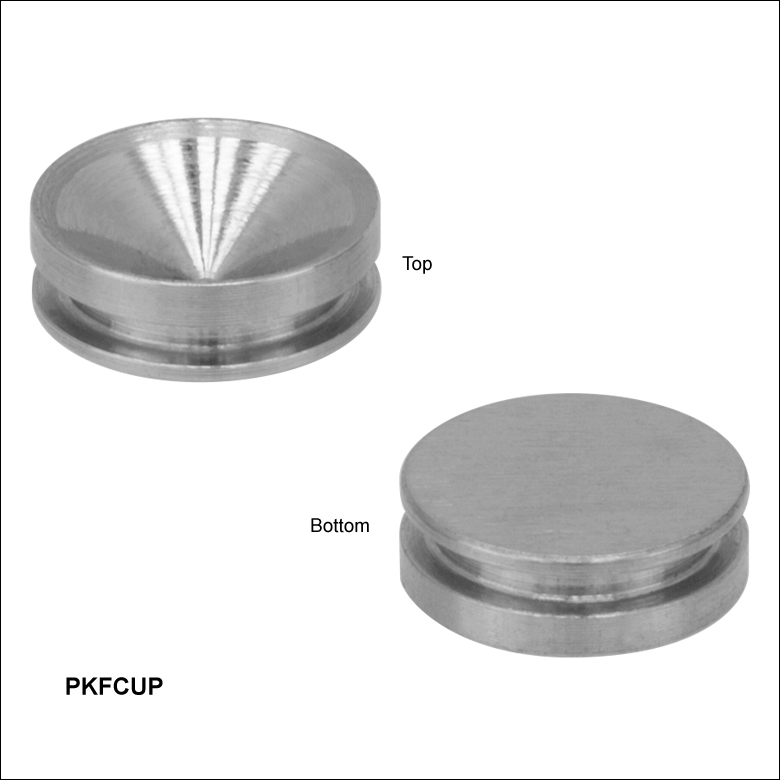
Zoom- Compatible with Our Piezoelectric Chips (Sold Above)
- Use with End Hemispheres Available Below
- Conical End Cups Accept Ball Contacts:
- From Ø1.5 mm to Ø3.0 mm (PKJCUP)
- From Ø2.6 mm to Ø5.0 mm (PKFCUP)
- From Ø3.6 mm to Ø7.0 mm (PKGCUP)
- Restricts Applied Stress to the Axial Direction
- Sold in Packs of 10
The PKJCUP, PKFCUP, and PKGCUP are 416 stainless steel conical end cups designed to be used with our piezoelectric chips when interfaced with the end hemispheres sold below. The conical cup can accept a ball contact, such as one of the end hemispheres available below, with a diameter from 1.5 to 3.0 mm (PKJCUP), 2.6 to 5.0 mm (PKFCUP), or 3.6 to 7.0 mm (PKGCUP). Using a ball contact with a piezo actuator ensures that the applied stress is restricted to the axial direction, limiting the probability of stress-induced failure. They can be affixed either to a flat face of a piezo chip or to the mechanical device that is being actuated. If affixing a cup to the chip itself, we recommend using an epoxy that cures at a temperature lower than 80 °C (176 °F), such as 353NDPK or TS10 epoxies or Loctite® Hysol® 9340.

 Zoom
Zoom| End Hemispheres | Flat End Plates | Compatible Piezo Chips |
||
|---|---|---|---|---|
| Item # | Diameter | Item # | Dimensions | |
| PKCESP | 2.0 mm | PKCEP4 | 2.0 mm x 2.0 mm x 0.4 mm | PA3CE(W), PA3CK(W), PA4CE(W) |
| PKDESP | 2.5 mm | PKDEP4 | 2.5 mm x 2.5 mm x 0.4 mm | PA4DG(W) |
| PKJESP | 3.0 mm | PKJEP4 | 3.0 mm x 3.0 mm x 0.4 mm | PA2JE(W), PA3JE(W), PA3JEA(W), PA4JE(W), PA4JK(W) |
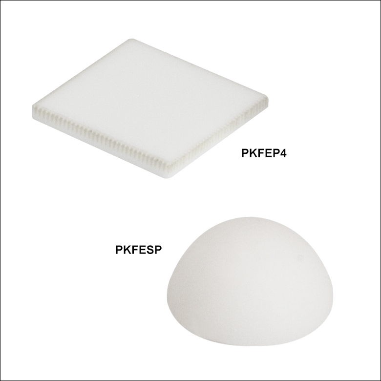
| PKFESP | 5.0 mm | PKFEP4 | 5.0 mm x 5.0 mm x 0.4 mm | TA0505D024(W), PA4FE(W), PA4FK(W), PA4FKY(W) |
| PKGESP | 7.0 mm | PKGEP4 | 7.0 mm x 7.0 mm x 0.4 mm | PA4GE(W), PA4GK(W) |
| PKHESP | 10.0 mm | PKGESP | 10.0 mm x 10.0 mm x 0.4 mm | PA4HE(W), PA4HK(W) |
- End Hemispheres and Flat End Plates in Six Sizes
- Hemispheres Provide a Single Point of Contact
for Actuation - Flat Plates Spread Force Across Piezo Face at Contact Point
- Sold in Packs of 16 or 25
The alumina end hemispheres and flat end plates used in our piezoelectric stacks are also available separately in six sizes (see the table to the right). The hemispheres can be used to create a single contact point between a piezo stack and a lever arm. Alternatively, a hemisphere can be used with a compatible conical end cup (sold above). End plates are used to spread the force at the contact point over the entire surface of the piezo stack. When selecting an end hemisphere or flat end plate to adhere to a piezo stack end face, it is important to match the bottom surface area of the hemisphere or plate to the cross section of the piezo stack in order to ensure that forces are spread evenly over the surface. The end hemispheres have a diameter tolerance of ±0.1 mm, and the end plates have a dimensional tolerance of ±0.04 mm. To secure the end hemisphere or the flat end plate to a piezo actuator, any epoxy that cures at a temperature lower than 80 °C is considered safe to use. We suggest using Thorlabs’ 353NDPK High-Temperature Expoy or TS10 Vacuum Epoxy. Additionally, Loctite® Hysol® 9340 can also be used.