 Products Home / Actuators, Adjusters, & Transducers / Piezoelectric Chips and Stacks / Ultrasonic Ring Chips & Langevin Transducers
Ultrasonic Ring Chips & Langevin Transducers
- Designed to Produce Ultrasonic Vibrations
- Chips Comprised of Single Layer of Hard PZT Material
- Langevin Transducers for Ultrasonic Welding Applications
- Resonant Frequencies from 15 kHz to 35 kHz
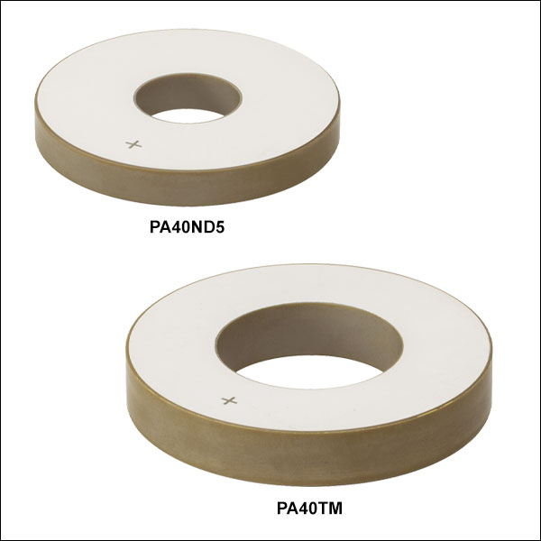
PA40ND5
35 kHz Ring Chip
PA40TM
26 kHz Ring Chip
PKT40A
Langevin Transducer,
20 kHz, 700 W
PKT40B
Langevin Transducer,
15 kHz, 500 W


Please Wait
| Piezo Selection Guide |
|---|
| Piezoelectric Ceramic Chips |
| Square |
| Square with Through Hole |
| Round |
| Ring |
| Tube |
| Shear |
| Benders |
| Single-Crystal Piezoelectric Chips |
| Square |
| Piezoelectric Ceramic Stacks |
| Discrete, Square |
| Discrete, Square with Through Hole |
| Discrete, Round |
| Discrete, Ring |
| Discrete, Hermetically Sealed |
| Discrete, Shear (1D to 3D Positioners) |
| Co-Fired: Square, Square with Through Hole, Round, & Ring |
| Co-Fired or Discrete: Square with Strain Gauges |
| Piezoelectric Crystal Stacks |
| Square |
| Mounted Piezoelectric Actuators |
| Ultrasonic Piezo Chips & Transducers |
| Vibrating Piezo Actuator |
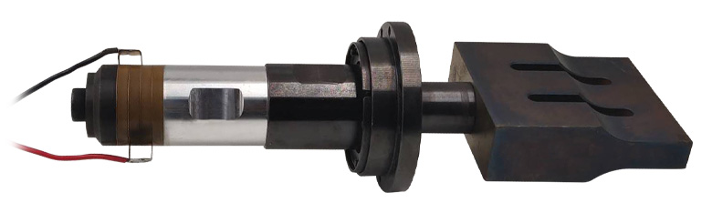
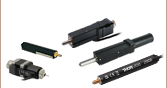
Click to Enlarge
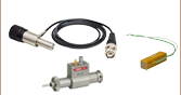
PKT40A Langevin Transducer (Left), Connector (Center), and Sonotrode/Horn (Right)
Features
- Chips of Hard PZT Material Designed for Ultrasonic Welding, Cleaning, Sensing, and Other Resonant Vibration Applications
- Two Ring Chips Available with Bare Electrodes:
- 35 kHz, 50 mm OD, 17 mm ID, and 6.5 mm Long
- 26 kHz, 60 mm OD, 30 mm ID, and 10 mm Long
- Langevin Transducers with Metal Housing for
Ultrasonic Welding - Drive Voltage Range of 0 - 5 kV
- Custom Options Available; Please Contact OEM Sales
Thorlabs offers hard PZT material ring elements as chips with bare electrodes for use in ultrasonic vibration applications and integrated into Langevin transducers designed for use in ultrasonic welding.
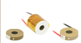
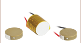
The PA40ND5 Ring Chip with 50 mm outer diameter (OD), 17 mm inner diameter (ID), and 6.5 mm thickness provides a 35 kHz resonant frequency as the work frequency; our PKT40A Langevin Transducer with four PA40ND5 chips provides a 20 kHz resonant frequency as the work frequency and an instantaneous power of 700 W. The PA40TM Ring Chip with 60 mm OD, 30 mm ID, and 10 mm thickness provides a 26 kHz resonant frequency as the work frequency; our PKT40B Langevin Transducer with four PA40TM chips provides a 15 kHz resonant frequency as the work frequency and an instantaneous power of 500 W.
The hard PZT material in these ultrasonic piezo chips and transducers can be driven at up to 5 kV, but operation above 3 kV may create an arc in the air. Protective measures such as silicone oil should be applied when the voltage is above 3 kV; for a complete list of specifications, see the tables below. We recommend driving clamped chips or transducers using a sine wave at the work frequency with a voltage of 0 - 5 kV. The graphs in the info icons in the tables below illustrate the sharp phase angle slope around the resonant frequency of the devices. The sharp phase angle slope is useful for tracking the resonant frequency which may shift during operation due to temperature changes.
Hard vs. Soft PZT Material
Soft PZT material has a large piezoelectric constant and is ideal for actuators in motion control applications. However, soft PZT has a relatively high dielectric loss factor of ~2% and would generate excessive heat when driven at high frequencies. We recommend using soft PZT actuators at less than 33% of their resonant frequency. Hard PZT material has a low dielectric loss factor and a high mechanical quality factor, making it ideal for high frequency driving and even resonant frequency driving. Driving hard PZT at its resonant frequency will generate maximum vibration amplitudes. The stroke or vibration displacement is harder to control at high frequencies, compared to soft PZT at low frequencies. The vibration of hard PZT is always used to generate vibration waves. When the resonant frequency is higher than the audible frequency range, the generated waves are termed ultrasonic waves and the device is called an ultrasonic transducer. These waves can be used for ultrasonic welding by rapid friction and heating, ultrasonic detection by wave reflection, and ultrasonic cleaning.
Piezo chips with custom dimensions, voltage ranges, and coatings are available. Additionally, customers can order these piezo chips in high-volume quantities. Please contact OEM Sales for more information.
Thorlabs' In-House Piezoelectric Manufacturing
Our piezoelectric chips are fabricated in our production facility in China, giving us full control over each step of the manufacturing process. This allows us to economically produce high-quality products, including custom and OEM devices. A glimpse into the fabrication of our piezoelectric chips follows. For more information about our manufacturing process and capabilities, please see our Piezoelectric Capabilities page.
- Build Blocks from Lead Zirconate Titanate (PZT) or BiScO3-PbTiO3 (BSPT) Powder
- Dry Press PZT Powder into Ring Elements with Binder in a Mold
- Purge Solvent and Binder Material Residues by Heat Treating the Elements
- Sinter the Elements to Fuse the Piezoelectric Pressed Powder and Grow PZT or BSPT Crystals
- Lap the Elements to Achieve Tight Dimensional Tolerances: ±0.2 mm for Each Element
- Screen Print the Outer Electrodes on the Elements
- Align the Individual PZT or BSPT Crystals Along the Same Axis by Poling the Elements
Ring Chip Operation Notes
Electrical Considerations
The electrode with the engraved '+' should be positively biased and the other electrode should be grounded. The absolute maximum voltage is 5 kV. Exceeding 5 kV will decrease the device’s lifespan and may cause mechanical failure. Reverse biasing the device may cause mechanical failure. Operating the device above 3 kV may create an arc in the air. Protective measures such as silicone oil should be applied when the voltage is above 3 kV.
When soldering wires to the electrodes, use a soldering iron at a temperature no greater than 370 °C (700 °F) for a maximum of 2 seconds per spot. Solder to the middle of the electrode, keeping the spot as small as possible.
Electrical Shock and Discharge Caution
During operation, high voltage is applied to the piezo and electrodes; do not touch the device by hand or with conductive materials to avoid injury or short circuit.
After being driven, the piezo is fully charged. Directly connecting the positive and negative electrodes may result in a spark and/or device failure. It is recommended to discharge using a resistor (>1 kΩ) between the positive and negative electrodes.
Attaching Devices to the Piezo Chip
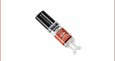
Any epoxy which cures at a temperature lower than 80 °C is safe to use with these PZT piezos. We recommend Thorlabs Item #s 353NDPK or TS10. Loctite Hysol 9340 is also usable.
Loads should only be attached to the center of the flat faces since the edges do not translate. Attaching a load to the edges may lead to mechanical failure.
Langevin Transducer Operation Notes
Electrical Considerations
The electrode that is in contact with the metal housing should be grounded and the other electrode should be positively biased. The absolute maximum voltage is 5 kV. Exceeding 5 kV will decrease the device’s lifespan and may cause mechanical failure. Reverse biasing the device may cause mechanical failure. Operating the device above 3 kV may create an arc in the air. Protective measures such as silicone oil should be applied when the voltage is above 3 kV.
When soldering wires to the copper foil electrodes, use a soldering iron at a temperature no greater than 370 °C (700 °F) for a maximum of 2 seconds per spot, soldering to the middle of the electrode.
Electrical Shock and Discharge Caution
During operation, high voltage is applied to the piezo and electrodes; do not touch the device by hand or with conductive materials to avoid injury or short circuit.
After being driven, the piezo is fully charged. Directly connecting the positive and negative electrodes may result in a spark and/or device failure. It is recommended to discharge using a resistor (>1 kΩ) between the positive and negative electrodes.
Attaching Devices to the Transducer
Loads should only be attached to the tapped hole in the base of the metal housing. The metal housing of the transducer can be held or clamped.
Caution: When operating at the resonant frequency, high voltages will be applied to the transducer which will generate high frequency forces as well as heat. Do not touch any part of the device to avoid risk of injury from electric discharge, vibration, or heat. When operated for extended periods, cooling the piezo chips and metal components by rapid air flow is recommended.
Storage Instructions
- Do not store the device at temperatures above 200 °C.
- Do not store the device in humid environments. The relative humidity (RH) should be less than 40%.
- Do not immerse the device in organic solvents.
- Do not use the device around combustible gases or liquids.
| Posted Comments: | |
Wenbin Zhong
(posted 2020-12-27 17:22:20.777) Do you have the amplitude information and suitable driver for these ultrasonic ring chips? YLohia
(posted 2020-12-30 09:52:33.0) Thank you for contacting Thorlabs. We do not spec the exact vibration amplitudes, as the vibration displacement is hard to control at high frequencies. It is estimated that the amplitudes of the PA40ND5 and PA40TM at their resonance frequencies and rated voltages are around 10um, the amplitudes of the PKT40A and PKT40B are several tens of microns. For the recommended driver, if your drive voltage is < 150V, we recommend the BPA100. For higher driving voltage, unfortunately, we currently do not offer a suitable driver. |

 Zoom
ZoomThese ring chips have bare electrodes with the positive pole marked by an engraved '+'; the other electrode should be connected to the negative pole of the driver or grounded. For more details, see the Operation tab.
| Item #a | Info | Resonant Frequencyb |
Drive Voltage Rangec |
Capacitanced | Dimensions | End Faces |
|---|---|---|---|---|---|---|
| PA40ND5 | 35 kHz | 0 - 5 kV | 2.3 nF ± 15% | Outer Diameter: 50.0 ± 1 mm Inner Diameter: 17.0 ± 0.5 mm Length: 6.5 ± 0.2 mm |
Screen- Printed Electrodes |
|
| PA40TM | 26 kHz | 1.9 nF ± 15% | Outer Diameter: 60.0 ± 1 mm Inner Diameter: 30.0 ± 0.5 mm Length: 10.0 ± 0.2 mm |
Ultrasonic Applications
- Thermoplastic Welding
- Cleaning Tanks
- Sonar & Sensing
- Mixing & Separating
- Vibrothermography

 Zoom
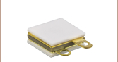
ZoomEach transducer contains a discrete stack of four ring chips clamped with a bolt between two metal housings. Each stack has copper foil electrodes; the positive pole only contacts the piezo chips, while the negative pole is also connected to the metal housing, which should be connected to the negative pole of the driver or grounded. For more details, see the Operation tab. The assembly bolt at the top is tightened to a specific torque and its thread is locked; it should not be loosened or removed. The PKT40A and PKT40B transducers can be mounted via the holes in the base which have M18 x 2.0 and M20 x 1.5 taps, respectively.
| Item #a | Info | Resonant Frequencyb | Powerc | Drive Voltage Ranged | Capacitancee | Dimensions | Joint Bolt |
|---|---|---|---|---|---|---|---|
| PKT40A | 20 kHz | 700 W | 0 - 5 kV | 10.0 nF ± 15% | Diameter: 50.0 ± 1 mm Max Width: 68.0 mm Height: 117.0 ± 1 mm |
M18 x 2.0 | |
| PKT40B | 15 kHz | 500 W | 9.0 nF ± 15% | Diameter: 60.0 ± 1 mm Max Width: 90.0 mm Height: 163.0 ± 1 mm |
M20 x 1.5 |