 Products Home


Introduction
In this tutorial we will look at some of the basics of piezoelectronic device structure and operation. These devices utilize piezoelectricity, a phenomenon in which electricity is created from pressure on the device. Piezoelectrics either produce a voltage in response to mechanical stress (known as direct mode) or a physical displacement as a result of an applied electrical field (known as indirect mode). Due to these modes, piezoelectric materials have found considerable use in both sensors and actuators and are often called “smart” or “intelligent” materials. One material in particular, lead-zirconate-titanate (PZT), has found prolific use for piezoelectric devices. Consequently, PZT is the ceramic material that makes up the bulk of piezoelectric actuator devices available on the market. It is not only piezoelectric but also pyroelectric and ferroelectric. PZT devices are capable of driving precision articulation of mechanical devices (such as a mirror mount or translating stage) due to the piezoelectric effect, which can be described through a set of coupled equations known as strain-charge (essentially coupling the electric field equations with the strain tensor of Hooke’s law):

and
 .
.
In matrix form, these equations can be written as

Click to Enlarge
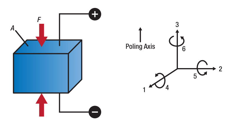
Figure 1.1 PZT Diagram with Labeled Axes
Here D is the electric displacement vector, ε is the strain vector, E is the applied electric field vector, σm is the stress vector, eσij is the dielectric permittivity, ddim & dcjk are the piezoelectric coefficients, and sEkm is the elastic compliance (the inverse of stiffness). The specific matrix elements are used to calculate the useful measures of PZT functionality, though the full derivation of these equations is beyond the scope of this tutorial.
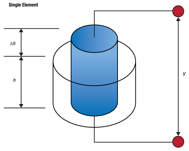
Figure 1.1 represents a simplified PZT device. These devices are normally constructed such that they are restricted to 1D operation with force and displacement occurring along the pointing axis (as defined by the electric field). The stress for such a configuration is given as F/A. The interesting consequence of this is that for any given mechanical strain upon a piezo, the force it can generate is proportional to the cross-sectional area of the piezo. This will be a concept we'll return to later when we discuss blocking force.
While we consider the case where the actuation of the piezo is restricted to 1D movement, in general a piezo can be deformed through other modes as well (see Figure 1.2). These modes of deformation that act orthogonally to the pointing axis create real world limitations in the actual use of PZT actuators. This concept is discussed in more detail later in this tutorial.
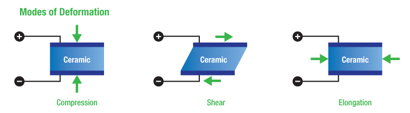
Figure 1.2 Deformation Modes
Actuator Types
There are 3 main categories for PZT actuators: low voltage, high voltage, and ring actuators. While there are bulk type actuators, the majority of modern actuators utilize a stacked design. Figures 1.4 and 1.5 demonstrate the difference between bulk and stacked actuators. For any given height, h, of an actuator, a stacked device can produce a larger proportional displacement, as demonstrated with the free strain equation:

or
 .
.
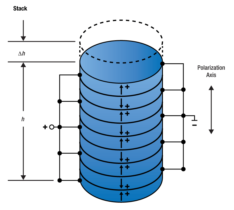
Here n is the number of stacks, and thus we can see that the fractional change in height is proportional to the number of stacks. These stacked structures can also boast a low driving voltage, quick response time, high force generation, and exceptional electromechanical coupling. While there is another variant of the actuator, the bimorph, it is outside the scope of this tutorial.
Click to Enlarge
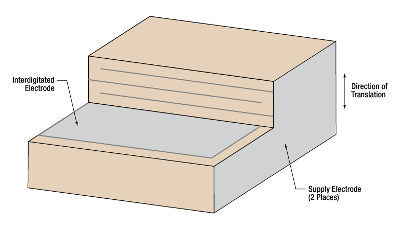
Figure 1.3 Three-Dimensional Cross Section of Multilayer Piezo with Interdigitated Electrodes
Low Voltage Actuators
Low voltage actuators tend to have operating voltages below 200 V. These devices are monolithic stacks devices, meaning that the stacked structure is produced through sintering rather than gluing individual layers (see Figure 1.3). While they can vary in size, these actuators tend to stay on the small-to-medium size and are usually rectangular. They have an electrical capacitance on the order of a few µF and tend to have a high elastic modulus. These actuators are cheap, available in large quantities, and great for precision articulation. Due to their smaller size, however, they are limited in the force that can be produced.
High Voltage Actuators
High voltage actuators have operating voltages that are typically above 500 V. Unlike their low voltage cousins, these actuators are not monolithic. The stacked structures are created by gluing together individual, finished PZT disks and electrodes. These actuators are usually cylindrical in shape and, for standard applications, much larger than the low voltage variant. The electrical capacitance for these devices is on the order of 100's of nF with a lower elastic module than the low voltage devices. The larger cross sectional area means that these actuators can produce higher forces and are also capable of withstanding higher temperature environments than their low voltage counterparts.
Ring Actuators
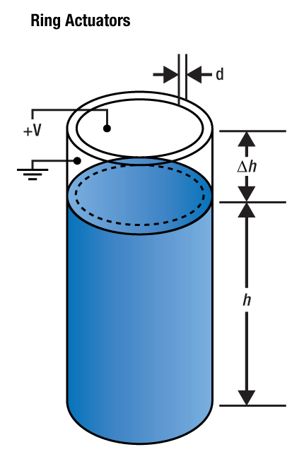
Ring actuators are hollow, cylindrical, stacked devices as shown in Figure 1.6. They can offer several advantages over the solid (bulk) actuators for performance and reliability. One of the largest factors in piezo performance decline or permanent damage is heat. Since PZTs are ceramic, they conduct heat very poorly; this can result in reduced piezo lifetime and reliability. The ring actuator can remove heat more quickly due to the dramatic increase in surface area. The increased efficacy in heat dissipation means that these actuators can be used at higher non-resonant frequencies without fear of thermal damage. Additionally, there are geometric advantages to the ring stacked structure. For the same volume of PZT material, the ring geometry is able to realize a much larger radius, thus increasing the actuator's mechanical stability, without the cost of a higher electrical capacitance.
Click to Enlarge
Figure 1.4 Expansion of a Piezo Element with Applied Voltage
Click to Enlarge
Figure 1.5 Stacked Piezo Design
Click to Enlarge
Figure 1.6 Ring Actuator Piezo Design
Thorlabs' PZT Capabilities
Click to Enlarge
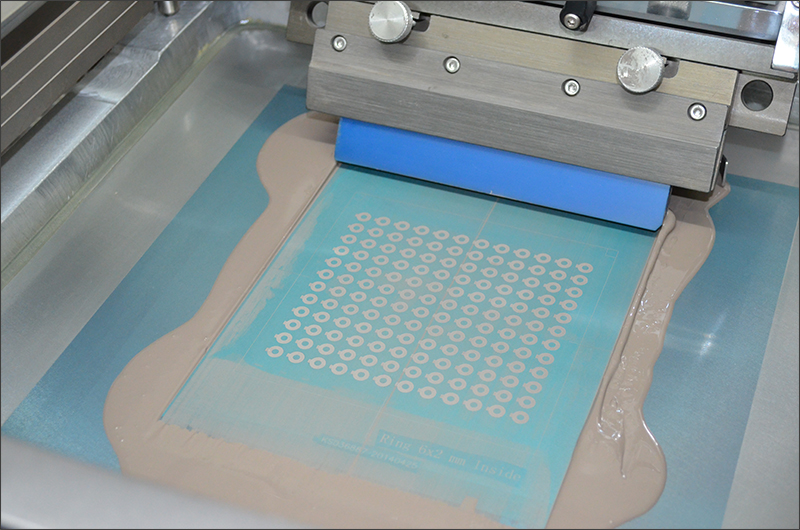
Figure 1.7 Screen Printing Silver Electrodes
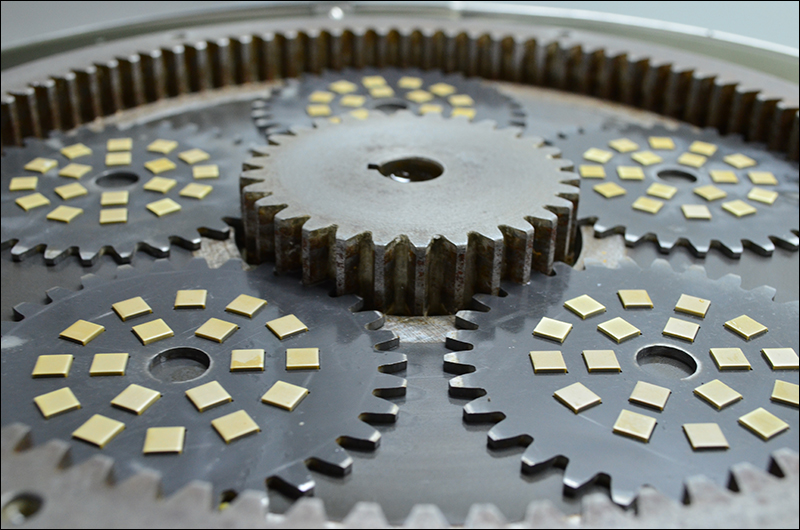
Thorlabs designs and manufactures our own PZT devices in house. Our Engineering and Manufacturing team has over 18 years of experience in piezoelectric design and manufacturing. The manufacturing process begins by selecting the proper piezo material based on the requirements of the planned actuator (e.g., size, displacement, driving voltage, etc.). For our multilayer devices, we screen print the inner electrodes using a silver/palladium paste and mask that is designed specifically for our stacked PZT devices. Once the stacks of ceramic blocks and interconnecting inner electrodes are assembled, they are placed in an isostatic press. This process increases the density of the PZT device, improving its mechanical properties and workability. The PZTs are then cut to the appropriate size and undergo a process known as Binder Burnout. By placing the PZTs through a designed heating cycle, the binder materials and solvent residues inside the ceramics are completely evaporated and removed. This helps to remove batch-to-batch performance variations and defects, increasing the reliability and reproducibility across the entire manufacturing process.
Binder burnout prepares the piezos for sintering. Sintering fuses the material together without melting the ceramic body, forming and growing crystallites until the optimum density is reached. For excellent dimension tolerances, we employ high-precision lapping machines to control the dimensions to within 5 µm in the direction of translation. From here, the devices are cleaned and prepared to be turned into fully functioning piezos. To do this, first the outer electrodes are screen printed onto the devices and then silver fired. Silver firing is an 8 - 12 hour process that enhances the adhesion between the silver electrodes and the ceramics.
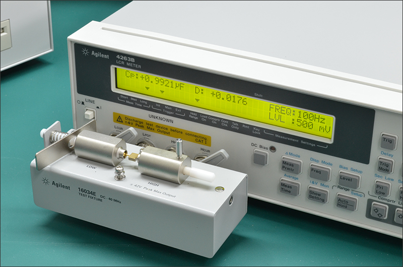
At this point, the devices are technically not piezoelectrics, since sintered PZT ceramics are isotropic. To turn our ceramics into piezos, the devices are put through the poling process, which subjects each device to a strong electric field across the electrodes, activating its piezoelectric properties. These newly formed piezo devices are then individually tested for capacitance, dissipation factor, resonant frequency, impedance, leakage, stroke, and piezoelectric charge constant d33. From start to finish, Thorlabs controls the entire manufacturing and testing procedures for our electrodes, giving us the flexibility and expertise to meet any piezoelectric application.
Our experts are continually pushing our offerings of standalone PZTs and integrated PZT devices.Thorlabs can also create special PZTs with proper calibration. Please contact Tech Support for more information.

Click to Enlarge
Figure 1.8 Cutting the PZT Block to Size
Click to Enlarge
Figure 1.9 PZT Devices on the Lapping Machine
Click to Enlarge
Figure 1.10 Piezoelectric Device in Testing Rig
Lead-zirconate-titanates (PZTs) are most often utilized for the precision articulation of devices such as mirror mounts or translating stages. As discussed in the Overview tab, PZTs are capable of producing small shifts with high force, load capacity, and stiffness. These characteristics allow piezos to drive relatively heavy loads over small, but precise, displacements. To understand how to incorporate a piezo into a system, or determine what piezo is appropriate for your needs, we will address some of the fundamental operational theory of PZTs. This will include an introduction to the mechanical, force, and electrical properties of PZTs.
Mechanical Properties
The mechanical capabilities of the PZT are often at the forefront of piezo considerations. The very basics of the piezoelectric effect, a physical displacement resulting from an applied electric field, make these devices ideal for precision movement and positioning. For example, a piezo actuator is commonly used to control the grating feedback in an external cavity laser and allows the user to select very specific wavelengths. These devices are also excellent for active stabilization of platforms and have even been used in NASA's space shuttles to prevent instrument vibration during takeoff or reentry.
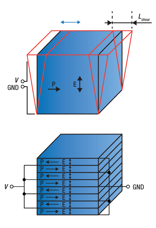
In the Overview tab, we had introduced 3 main types of actuators: low voltage stacked, high voltage stacked, and ring. The mechanical movement of the stacked actuators is very similar, even though there are electrical differences between the low and high voltage variants. Figure 1.2 in the Overview tab shows the common modes of deformation, which not only includes the intended compression but also elongation and shear. Elongation is similar to compression, except along the [1,1] or [2,2] axis. Shearing occurs when the applied electric field is orthogonal to both the polarization and direction of movement.
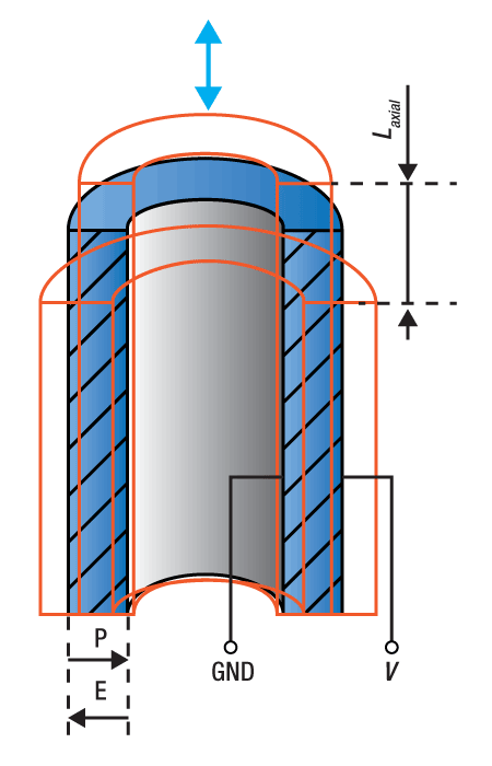
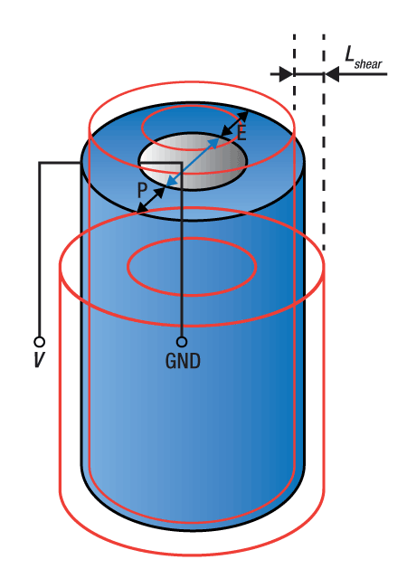
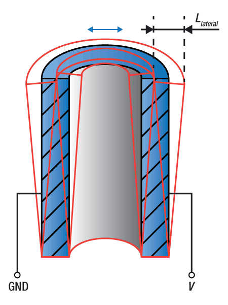
As with elongation, the displacement in shearing actuators is extended by using stacks. Ring actuators, being composed of stacks, are described similarly. However, there is a bulk variant known as a tube actuator. This actuator is also a hollow cylinder, the same as the ring actuator, with metalized inner and outer surfaces for electrical contact. In general, stacked ring actuators are able to realize higher strain rates and are available in low voltage structures, and because of this, they are often chosen over tube actuators. However, tube actuators can be engineered to produce axial displacement, radial displacement, and bending. Bending tube actuators can often be found in devices such as XY scanning tubes. These displacements are given in the equations below.
Click to Enlarge
Figure 2.2 Axial Displacement
Click to Enlarge
Figure 2.4 Bending Actuators


Click to Enlarge
Figure 2.5 Example of PZT Hysteresis Over a Range of Applied Voltage Differences
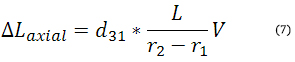
Here L is the length of the actuator, r1 is the inner radius, and r2 is the outer radius. Both the shearing and tube actuators demonstrate that the piezo can utilize various strain constants to achieve the desired articulation. At sub-resonant frequencies, the displacement (often referred to as stroke) of the piezo follows the applied voltage signal immediately. The magnitude of the stroke is dependent upon the change in voltage applied to the piezo up to the Free Stroke length.
In an open-loop system, the stroke will demonstrate hysteresis, similar to that shown in Figure 2.5. The exact shape and characteristics of the hysteresis is heavily dependent upon the applied voltage difference as well as environmental and system conditions such as temperature or the applied load. This is due to the source of hysteresis in PZTs, crystalline polarization effects, and molecular friction.
The hysteresis can be reduced by driving smaller potential differences, though this will also limit the range of the stroke. Another alternative is charge control; as the name implies, the user controls the charge applied to the PZT instead of the voltage. The hysteresis can be reduced from about 10 - 15% in the voltage control case to about 2% by using charge control. However, charge control is generally not sufficient for precision movement over long periods of time. Moving to a closed-loop system can essentially eliminate the hysteresis altogether. Precision articulation is often performed through voltage control of a PZT stack using a feedback loop. It should be noted that, when using a servo loop, the dynamics of the system (resonant frequency, bandwidth, etc.) will be determined by the aggregate circuit itself, so care should be taken when designing a servo loop to ensure that it meets the parameters of the task.
Click to Enlarge
Figure 2.6 Example of a PZT Working Graph
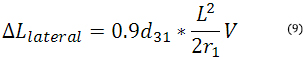
Force & Stroke
Along with mechanical shift, the force generation of the piezo is another important factor. The amount of force that can be generated by the piezo is dependent upon the applied load to the piezo and how it changes with increasing stroke. For instance, if the force is constant while the piezo is active, the piezo exerts a net zero force, and the maximum stroke is observed. Forces that exhibit strong dependence upon stroke, however, necessitate large mechanical forces by the piezo. In these situations, the stroke is reduced. Figure 2.6 shows a typical stroke/force relationship. This graph also marks two very important parameters of piezo actuators: the Free Stroke (ΔLFS) and the Blocking Force (FBlock).
A piezo's free stroke is defined as the stroke in the absence of any applied force (such as a preload). A voltage is applied to a piezo free from load, and the resulting displacement is measured; this gives the free stroke. The blocking force, on the other hand, is defined as the maximum force that can be generated by the piezo. This parameter is typically measured by first allowing the piezo to expand without force; then an external force is applied until the piezo is compressed back to its original length. This measured force is then referred to as the blocking force. From these two values we can also define the stiffness (kA) of the piezo actuator:
 .
.
The actuator's stiffness is helpful for determining the performance of the piezo as well as choosing the appropriate preload force.
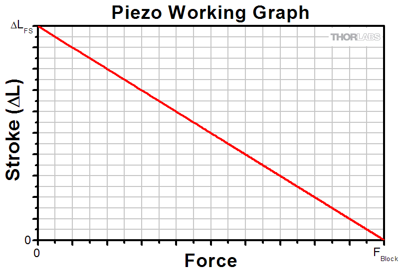
We can examine a couple of systems to see the effects of preloading and performance of a piezo actuator. Figure 2.7 shows the working curve for an actuator with (A) no load and (B) a load with low stiffness (kL << kA where kL is the load stiffness). Equation 11 shows the approximate displacement of the actuator under load:
 .
.
In this case, we see a slightly reduced stroke. This is due to the force the spring exerts back on the piezo, which causes a "self-compression" that reduces the overall stroke of the actuator. If we think of stroke and force as complementary properties of the piezo actuator, we see that a low stiffness spring produces near the free stroke displacement, but with an effective force that has been greatly reduced from the blocking force. A high stiffness spring (kL >> kA) will perform in just the opposite manner. The effective force in this case is given by
 .
.
Here we see that the effective force will approach the blocking force for high stiffness springs. In exchange for the high force generation, under this condition, the stroke is heavily reduced.
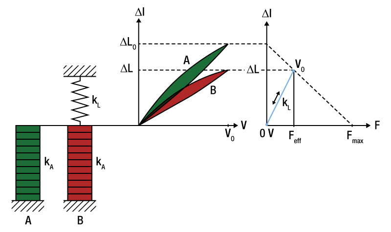
If a constant mass is used as a load on an actuator, a stroke-independent force (m*g) is applied to the actuator. The working curve for this is shown in Figure 2.8. The steady mass force offsets the zero point on the actuator, but since the force is constant, the work curve looks very similar to that of an unloaded actuator. Thus the stroke remains close to the free stroke. A constant physical load only shifts the zero point by providing an initial compression and maintains the stroke range.
In any real system, the performance is going to be a combination of spring and constant force loads. Preloading with a spring load can provide the steady-state offset as well as the stroke-dependent forces. Preloading uses a relatively low stiffness spring preload (kL ≤ kA/10) and in some PZT designs it is built into the actuator assembly itself (typically referred to as Preloaded Piezos). The stiffness of the preload spring should not be any greater than kA/10 or else the stroke will be significantly reduced (as seen in Figure 2.7). For example, if the preload spring has the same stiffness as the actuator, the stroke is cut in half. While it may seem that preloading is a disadvantage as it consumes a bit of the stroke, PZTs are ceramic and, as such, are susceptible to certain stresses. The PZT is particularly vulnerable to large pulling or shear forces, and a system needs to be able to isolate the actuator from them. A spring-loaded actuator can actually increase the piezo's pulling performance and enhance dynamic push/pull applications.
Electrical
In general, PZTs are usually operated well below their resonant frequency (fo), particularly when used as a precision positioner. The reason for this is to keep the phase difference between the applied voltage and the PZT's displacement as low as possible. A piezo system is typically run anywhere between DC and >10 kHz.
The resonant frequency of the PZT is dependent upon the length of the piezo stack; the shorter the stack, the higher the resonant frequency. Additionally, driving a load of mass M can change the resonant frequency. Equation 13 shows how to calculate the adjusted resonant frequency with the addition of a load:
 .
.
Here m is the mass of the actuator and M is the mass of the load. While the minimum time it takes the piezo to expand is approximately 1/(3fo), the maximum velocity of the actuator is dependent upon the peak current of the power supply being used. Additionally, the acceleration response of the actuator is dependent upon the slew rate of its power supply. Once the piezo expands or contracts to the nominal extension, there will follow a damped oscillation in the length of the actuator around this position. Controls can be implemented to mitigate this oscillation, but doing so may slow the response of the actuator.
When operated below its resonant frequency, an actuator behaves like a capacitor and can be modeled as such. The capacitance value of an actuator depends upon the area and length of the actuator, and in stacked structures, the capacitance also depends on the number of layers, given by
 ,
,
where C is the capacitance, n is the number of layers, ε is the permittivity, A is the cross-sectional area, and hL is the thickness of the piezo layer. Additionally, PZTs have exceptionally low current leakage rates. As such, in systems using the actuator statically, the PZT will use very little energy and create very little heat. However, for dynamic applications, the behavior can be quite different and will require significantly higher voltages to drive, while heat generation may become an issue that needs to be addressed. This is due to the linear relationship between the generated heat power (P) and operational frequency (f) for a PZT, which is given by
 .
.
In Equation 15, tan(δ) is the dielectric loss factor, C is the capacitance of the actuator, and Vpp is the peak-to-peak driving voltage. For most standard PZT actuators, this can be about 2% of the total input power, which can be significant for high voltage actuators. However, for high frequency or amplitude systems, the percentage grows even larger and a cooling servo may be required for proper operation.
Static Operation
Static operation of an actuator is relatively straight forward. Static operation covers not only using a PZT to hold a position but also as a slow dynamical positioner. In this regime of actuator use, we must examine the energy stored in the PZT and the currents associated with charge transport. The energy is given by
 .
.
The current (charge transport) is given by
 .
.
For static holding, the driver needs to only compensate for the very low leakage current from the PZT. Slow positioning requires a very low current as well. Therefore, in static or low dynamic operation the currents necessary are very small and most drivers should suffice.
Precision control typically will utilize a servo circuit to control the PZT. This closed-loop circuit will remove the hysteresis found in the open-loop configuration. Other important parameters, such as bandwidth, rise time, gain, unity gain, etc., will be determined primarily by the circuit itself. The speed of the circuit tends to be relatively slow, which relaxes some of the constraints on driver bandwidth discussed below. Additionally, this configuration cannot operate in a pulsed mode.
Dynamic Operation
For continuous dynamic operation of an actuator, the PZT is typically driven with a time-varying voltage source such as a sine wave, triangle wave, or sawtooth function. While operating at a high frequency, the actuator runs through a large number of mechanical cycles, and thus, concerns of longevity and durability become important. To produce a system that is rugged, robust, and performs accurately over long time scales, it is necessary to match the PZT with an appropriate PZT amplifier. The amplifier must be able to source the current required by the PZT over the desired frequency range for PZT action. The exact current, voltage, and frequency values will depend on the specifications for the PZT being used and the type of drive signal (sine, triangle, etc.). We will examine here the two most common drive functions: sine and triangle.
A common specification given with piezo amplifiers will be the average current (Iave). This must be sufficiently high to meet the current requirements of the piezo. For continuous sine wave operation, the average current of the piezo is given by the following equation:
 .
.
Here, C is the capacitance, Vpp is the peak-to-peak voltage drive, and f is the drive frequency. Once the drive voltage and frequency are determined, the average current is calculated. The piezo amplifier should be capable of sourcing both the necessary voltage and current. The average power that must be provided by the driver is then given by
 .
.
It is also possible to pulse an actuator with single sine wave pulses. In pulse mode, we look at the peak power necessary for the piezo; the amplifier must be able to maintain this current for at least half of the period for single pulses. If using a repetition rate, then the time average of the peak current cannot exceed the average current. The maximum current is given by
 .
.
The maximum power necessary for this mode of operation is given by
 .
.
When using a triangle wave as the drive source, both Iave and Imax are important. The driver must be able to source the maximum current, and the average current determines the restriction on the driving frequency:
 .
.
When modulating at some frequency, f, it is important to keep in mind the bandwidth of the piezo driver itself, particularly when using functions that deviate from a sine wave. If the bandwidth of the driver is close to or less then the frequency being driven, then there can be considerable aliasing of the drive signal. To avoid this, use a driver with a bandwidth about 10 times greater than the drive frequency.
Piezo systems can also be incorporated into pulsed applications, such as injection or hydraulic valves, switch relays, etc. In this mode, the goal is to cause the PZT displacement in as short a time as possible in order to make a fast switch. Response times down to the µs level and accelerations in access of 10000*g are possible and would require significant peak current from the driver. As mentioned earlier, the fastest that an actuator can reach nominal displacement is 1/(3fo). From here we can approximate the minimum rise time for displacement in a pulsed system:
 .
.
Driver bandwidth again comes into play as a limitation. The rise time of the driver must be smaller than the response time of the PZT. As such, it is best to try to choose a driver that has a bandwidth that is 2 - 3 times larger than the resonant frequency.
In the previous tabs, we have discussed the general theory of piezoelectric operation and dynamics. The next step is to learn how to apply these concepts to a working system. While piezos can be reliable actuators, they are often kept to the smallest dimensions possible, driven near their limits, and/or implemented improperly in a system. Piezos are sometimes viewed as the weakest link in a mechanical system, particularly because improper use can cause cracking or failure in the piezo actuator. Failure modes in piezos may not be immediately observable but can affect long-term reliability and reproducibility.
Mounting PZT Devices
Piezoceramics are brittle and have low tensile strength. Avoid loading conditions that subject the actuator to lateral, transverse, or bending forces. When applied incorrectly, an external load that may appear to be compressive can, through bending moments, cause high tensile stresses within the piezoelectric device. Improperly mounting a load to the piezoelectric actuator can easily result in internal stresses that will damage the actuator. To avoid this, the piezoelectric actuator should be interfaced with an external load such that the induced force is directed along the actuator's axis of displacement. The load should be centered on and applied uniformly over as much of the actuator's mounting surface as possible. When interfacing the flat surface of a load with an actuator capped with a flat mounting surface, ensure the two surfaces are highly flat and smooth and that there is good parallelism between the two when they are mated. If the external load is directed at an angle to the actuator's axis of displacement, use an actuator fitted with a hemispherical end plate or a flexure joint to achieve safe loading of the piezoelectric element. Thorlabs can also design custom mounting options to meet various user requirements (contact Tech Support for more information).
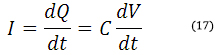
One of the most common mistakes in mounting a PZT actuator is a mismatch in the mating faces, particularly in applications that do not use a floating axis. It’s important to note that when mounting flat-face to flat-face, even slight misalignments between the two faces will produce edge squeezing and high pressures at localized spots. Edge squeezing often results in damage to the ceramic PZT. Figures 3.1 and 3.2 highlight a few improper and proper mounting geometries.
Click to Enlarge
Figure 3.1 Improperly and properly mounted PZT actuators. In Frame A, the PZT will experience significant edge squeezing that could lead to failure of the PZT stack. This edge squeezing can be fixed by using a hemispherical plate (shown in Frame B), a PKFCUP (shown in Frame C with a hemispherical end plate PZT), or a flexure mount that ensures full contact with the PZT face (Frame D).

Click to Enlarge
Figure 3.2 PZT stack actuating a lever arm. Using a flat face PZT, as shown in Frame A, can cause edge squeezing that could lead to failure of the PZT stack. Using a hemispherical plate, as shown in Frame B, ensures proper contact with the PZT and restricts stress to the axial direction.
When mounted between plates, a ball or flexure tip is recommended to avoid bending and shear forces from acting upon the actuator. Thorlabs' Discrete Piezoelectric Stacks provide options for both flat and hemispherical end plates; additionally, we offer the PKFCUP Conical End Cup to aid in the proper mounting of the PZT stack (illustrated in Figure 3.1). It is important to avoid excessive torque or lateral forces when mounting and operating the actuator.
If using glue to secure a load to a piezo actuator, care must be taken to ensure proper mounting. Any epoxy that cures at a temperature lower than 80 °C is considered safe to use. Thorlabs’ 353NDPK High-Temperature Epoxy and TS10 Vacuum Epoxy are appropriate for use with our piezos. Additionally, Loctite Hysol 9340 can also be used to epoxy PZTs. It is important to secure loads only to the ceramic mounting plates of the PZT; the sides of the PZT are not meant for translation. Consequently, when gluing a load to a PZT, the glue should only contact the mounting plates. Use of excessive glue should be avoided, as it may flow to the sides of the piezo and possibly cause mechanical failure.
In the Operational Theory tab, we discussed the effects of preloading on an actuator. Preloading is advantageous for mounting applications as well. Since PZTs are susceptible to pulling forces, an external preload can be used to reduce the pulling force on the actuator, thus extending its lifetime and aiding in reliable and reproducible operation.
Environmental Warnings
The lifetime of PZTs depends on the voltage they are operated at, the ambient temperature, and the humidity level. Standard PZTs are susceptible to damage in high humidity (>75%) environments. High humidity increases the likelihood of electrolytic reactions, which occur at the electrodes of the piezoelectric devices when a voltage is applied. These reactions both generate hydrogen and result in metal dendrites growing from the cathode towards the anode. The hydrogen liberated by the electrolytic reaction chemically reacts with and degrades the piezoelectric material. Dendrites that grow to electrically connect the cathode and anode result in increasing levels of leakage current. If it is necessary to operate the PZT in a high humidity environment, keep the ambient temperature as low as possible, operate at the lowest possible voltages, and use either hermetically sealed stacks or a dry air flushing system.
Additionally, PZTs can be damaged in a light noble gas (e.g., He or Ar) or hydrogen environment. This damage is caused by dielectric breakdown in the PZT stack, which will be induced by such gases. To reduce the risk of damage in such an atmosphere, it is suggested that low voltage actuators be employed and that they be operated at as low an operating voltage as possible.
PZTs can be operated under vacuum but care must be taken when doing so. The outgassing rate of the specific PZT actuator can affect the vacuum system and limit the use of the actuator. The outgassing rate will vary amongst different models, so it’s important to make sure you have the proper value for the model being used. Furthermore, dielectric breakdown can be induced more easily at certain pressures. For instance, air acts as a strong insulator at atmosphere and below 10-2 Torr. However, between 0.01 and 10 Torr, air no longer acts as a strong insulator and dielectric breakdown can occur more readily at these pressures. Hence, PZTs should not be operated at pressures between 0.01 and 10 Torr.
Driver Properties
We have spent considerable time discussing the general properties of PZTs: design, mechanical & electrical characteristics, frequency response, etc. However, a piezo is not operated in isolation; a PZT actuator is typically driven by an electrical input from an external source. Because a PZT converts a small electrical potential to a correspondingly small displacement, small electrical noise fluctuations from the driver will be reflected in the actuator as mechanical noise. As such, a driver providing ultra-low-noise, high-stability linear amplification is necessary to drive precision positioning. We can estimate the mechanical noise using the following equation:
 .
.
Here ΔLnoise is the mechanical noise of the system, ΔVnoise is the voltage noise from the amplifier, and ΔLmax is the maximum displacement at max potential (Vmax). Thus for precision positioning applications, it is imperative to select the appropriate driver with the lowest noise.
For dynamic motion control, high power switching supplies are often used (since the driver must provide enough current to charge the capacitance of the PZT), though they tend to have larger noise amplitudes. Here the peak current is the value of merit since it will affect the charging time. When modulating a PZT device, if the power supply cannot provide the necessary current, the output signal will become distorted, limiting displacement.
Frequency modulation was discussed in some part under the Dynamic Operation section of the Operational Theory tab. For various modulating waveforms, the peak current is given by one of the following:
Sine
 .
.
Triangle
 .
.
Square
 .
.
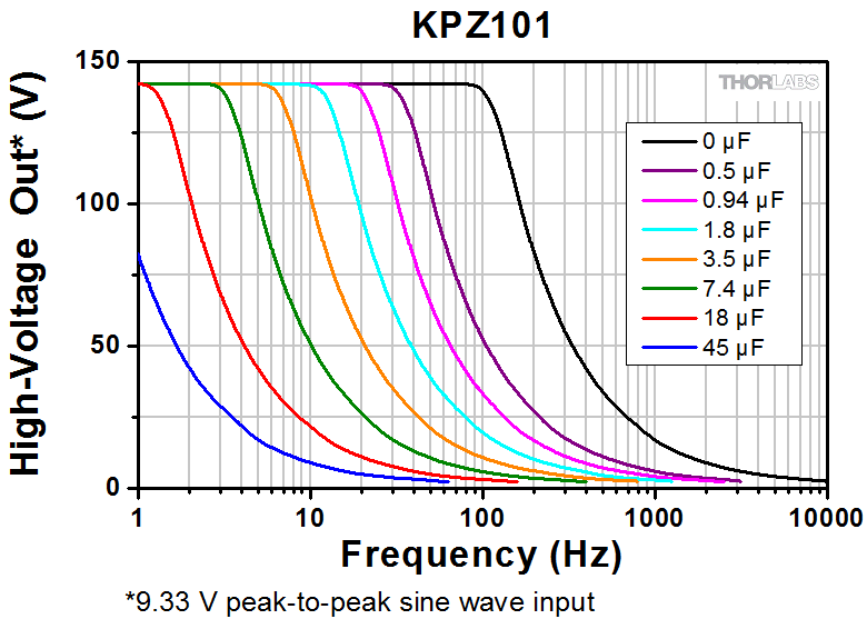
Click to Enlarge
Figure 3.3 This figure shows the frequency response curves for the previous-generation KPZ101 PZT controller at different capacitive loads.
In these equations, f is the drive frequency, C is the capacitance of the PZT actuator, Vpp is the peak-to-peak voltage from the supply, and Δt is the voltage rise-time. The power supply must not only be able to achieve the maximum current but also have the bandwidth to modulate the PZT capacitance at the desired frequency. For this we turn to the frequency response curve of a piezoelectric driver (see Figure 3.3 for an example distribution of frequency response curves). PZT drivers will produce different frequency response curves as the capacitance varies. The bandwidth is defined as the frequency at which the output power has dropped by half (3 dB) and a significant phase-shift is present. A general rule of thumb is that for accurate signal reproduction, one should drive a PZT at a frequency that is ≤10% of the amplifier’s bandwidth for the given capacitance of that PZT.
Another driver option would be a Charge Driver. A charge driver uses electrical charge instead of voltage to control the displacement of the PZT actuator. There are a few advantages of using a charge driver over a voltage driver. One of the biggest advantages is a reduction in hysteresis. During voltage control, the hysteresis can be as high as 15%. However, by using charge control, the hysteresis can be reduced to as low as 2%, thus dramatically increasing displacement precision for dynamic applications. Another major advantage is that charge control offers increased dynamic stiffness compared to voltage control. This is due to the fact that, while under charge control, mechanically generated charge is not dissipated. While charge control will reduce hysteresis, for high accuracy positioning applications it is still recommended to use a closed-loop system. See the Operational Theory tab for additional information about hysteresis when driving piezos.
Piezo Lifetime
PZTs are quite susceptible to damage from shear and pull forces; however, with proper mounting care, this failure mode can be mitigated, if not eliminated. Generally speaking, a PZT is not going to suffer mechanical failure from long-term use. A PZT can perform billions of cycles without a change in performance so long as it has been properly mounted and driven. Since a PZT is a capacitive device, the applied voltage has a significant affect on its lifetime. As such, when operating PZTs, it is best to try to keep the average voltage as low as possible.
There are no set rules for a piezo’s lifetime. Mounting, driving, environment, load, modulation frequency, etc. all affect a piezo's long-term operational stability. However, by understanding how PZTs work, their limitations, and dynamics, and by using that understanding to implement them properly, a user can keep a PZT system operational and reliable for many years.
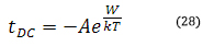
Here we present some general guidelines that can be followed to improve the overall lifetime of your piezo. Aside from proper mounting, there are three factors that play key roles in the lifetime of a piezo: operating voltage, ambient temperature, and relative humidity. There have been several studies looking at the effects of these three factors on the longevity and reliability of PZTs at DC voltages [1 – 3]; we will briefly discuss some of those results.
It was found that increasing the applied voltage, temperature, or humidity will dramatically decrease the lifetime of a PZT actuator. For example, the lifetime of a piezo with 40 µm layer thickness run at 80 °C saw a decrease from 3000 hours to just 70 hours when the applied voltage was doubled from 200 V to 400 V. In terms of temperature, the same type of piezo run at 200 V experienced a drop in lifetime from 3000 hours to 30 hours when the temperature was increased from 80 °C to 200 °C [3]. The general relationship for the dependency of lifetime on voltage and temperature is given in Equations 28 and 29.
 .
.
 .
.
Here, tDC is the DC lifetime of the piezo, A and n1 are constants, W is the activation energy, k is Boltzmann’s constant, T is the temperature in Kelvin, and VDC is the applied DC voltage. From Equation 28 we can see that the relationship between lifetime and temperature looks very similar to an Arrhenius relationship. Indeed, the log of lifetime is linearly dependent upon the inverse of the temperature. Equation 29 shows the relationship between lifetime and the applied voltage. Humidity, too, has a profound impact on the lifetime of the piezo device. While it was originally believed that water degraded a PZT through the electromigration of silver electrodes around the grain boundaries, later investigation found that water can impact the ceramic bodies of PZT devices and thus is not limited to just electromigration [4]. Since the mechanisms through which water damages a PZT are complex and not fully understood, a mathematical relationship has yet to be presented. However, it was found that increasing the relative humidity from 10% to 80% decreased the lifetime by 2 - 3 decades [3].
To assist in temperature control, please see our selection of thermoelectric coolers. Temperature and humidity can be monitored using our USB Temperature and Humidity Logger.
Selecting an Actuator and Driver
The application will always define the PZT and driver necessary. There is no universal PZT appropriate for all cases. As such, the user must evaluate the needs of a given system and find the PZT and driver that match these needs as well as each other. To determine the proper actuator and driver, here are a few helpful questions to consider:
- What is the necessary shift/stroke for the application?
- What forces will be generated by the PZT action?
- What is the static preload on the PZT?
- What external mass is acting upon the actuator?
- At what frequency does the system need to be modulated?
- What is the necessary displacement at the modulation frequency?
- What is the desired maximum frequency at the maximum displacement?
- How fast must the actuator act (i.e. fall and rise time)?
Not all of these questions may be applicable for a given application. For instance, if the system is to be a precision position or low dynamic system, then the first 3 questions would be most applicable as the actuator would not be modulated. If, however, the interest was for a system with dynamic operation, questions 4 - 8 will help select the appropriate driver (by calculating necessary Imax and Iave values).
When selecting an appropriate driver, keep in mind that less is more, as overdriving a PZT can damage it. The driver should match the voltage requirements of your PZT and no more. Do not use a driver that outputs significantly higher voltage than the PZT is rated for. A properly matched PZT and driver will help increase the efficacy of system operation as well as its lifetime.
[1] K. Nagata and S. Kinoshita, Jpn. J. Appl. Phys. 34, 5266 (1995)
[2] K. Nagata and S. Kinoshita, Ferroelectrics 195, 163 (1997)
[3] K. Nagata and J. Thongrueng, J. Korean Phys. Soc. 32, S1278 (1998)
[4] W. P. Chen et al., Appl. Phys. Lett. 80, 3587 (2002)
Piezo Bandwidth
Knowing the rate at which a piezo is capable of changing lengths is essential in many high-speed applications. The bandwidth of a piezo controller and stack can be estimated if the following is known:
- The maximum amount of current the controllers can produce. This is 0.5 A for our BPC Series Piezo Controllers, which is the driver used in the examples below.
- The load capacitance of the piezo. The higher the capacitance, the slower the system.
- The desired signal amplitude (V), which determines the length that the piezo extends.
- The absolute maximum bandwidth of the driver, which is independent of the load being driven.
To drive the output capacitor, current is needed to charge it and to discharge it. The change in charge, dV/dt, is called the slew rate. The larger the capacitance, the more current needed:

For example, if a 100 µm stack with a capacitance of 20 µF is being driven by a BPC Series piezo controller with a maximum current of 0.5 A, the slew rate is given by

Hence, for an instantaneous voltage change from 0 V to 75 V, it would take 3 ms for the output voltage to reach 75 V.
Note: For these calculations, it is assumed that the absolute maximum bandwidth of the driver is much higher than the bandwidths calculated, and thus, driver bandwidth is not a limiting factor. Also please note that these calculations only apply for open-loop systems. In closed-loop mode, the slow response of the feedback loop puts another limit on the bandwidth.
Sinusoidal Signal
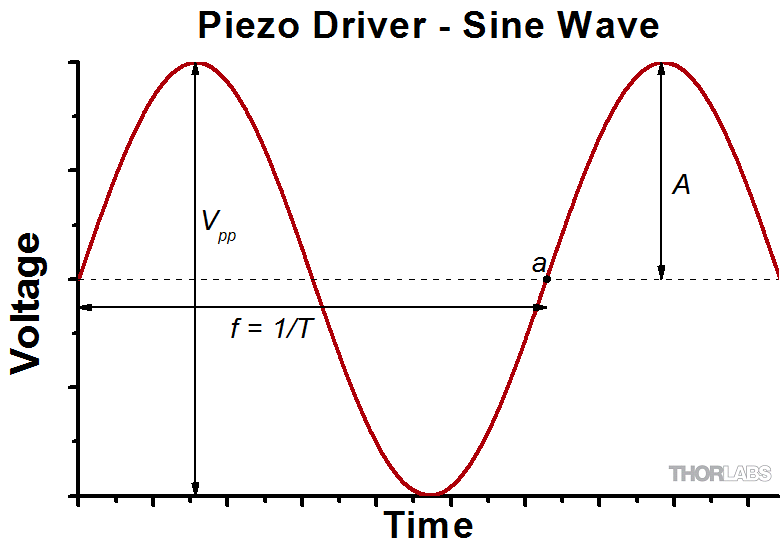
The bandwidth of the system usually refers to the system's response to a sinusoidal signal of a given amplitude. For a piezo element driven by a sinusoidal signal of peak amplitude A, peak-to-peak voltage Vpp, and frequency f, we have:

A diagram of voltage as a function of time is shown in Figure 4.1. The maximum slew rate, or voltage change, is reached at t = 2nπ, (n=0, 1, 2,...) at point a in Figure 4.1:
 .
.
From Equation 30:
 .
.
Thus,
 .
.
For the example above, the maximum full-range (75 V) bandwidth would be
 .
.
For a smaller piezo stack with 10 times lower capacitance, the results would be 10 times better, or about 1060 Hz. Or, if the peak-to-peak signal is reduced to 7.5 V (10% max amplitude) with the 100 µm stack, again, the result would be 10 times better at about 1060 Hz.
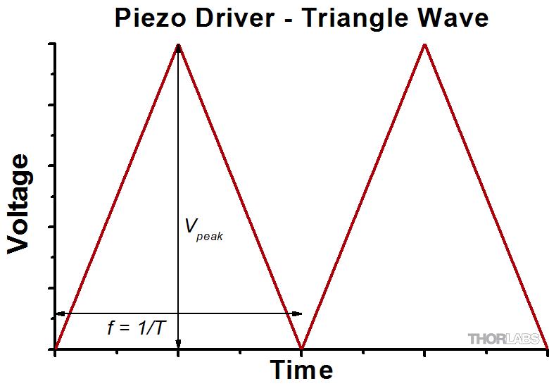
Triangle Wave Signal
For a piezo actuator driven by a triangle wave of max voltage Vpeak and minimum voltage of 0, the slew rate is equal to the slope:

Or, since f = 1/T:
 .
.
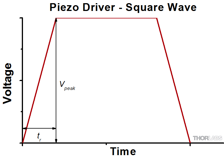
Square Wave Signal
For a piezo actuator driven by a square wave of maximum voltage Vpeak and minimum voltage 0, the slew rate limits the minimum rise and fall times. In this case, the slew rate is equal to the slope while the signal is rising or falling. If tr is the minimum rise time, then

or
 .
.
| Posted Comments: | |
Bradley Kingsley
(posted 2023-03-30 12:54:57.46) From the analytical solutions solved for displacement on the PK2JA2P1 Piezo stack, the claimed displacement is 8 um at 75 volts and no load. I am getting 8 ustrain, not 8um. Due to solving strain=d*E, for free displacement. Please comment on if errors are in my calculation.
Thank you,
Bradley Kingsley
Mechanical Engineering Senior NAU
This info will be used for educational purposes only, a team project for my adaptive materials course. cdolbashian
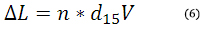
(posted 2023-04-13 10:32:22.0) Thank you for contacting Thorlabs. We use this equation "Δh=n*d33*V" to estimate the displacement. Here n is the number of stacks, d33 is the piezoelectric coefficient, V is the applied voltage. For PK2JA2P1, n=188, d33=710 pC/N, V=75 V, and the estimated displacement is calculated to be 10 um. The 8 um displacement of PK2JA2P1 we post on the website is a measurement data. The difference comes from some inactive area around the actuator’s edge. Runmin Li
(posted 2022-12-09 09:52:01.84) Does Thorlabs have adhesives to adhere Piezo and mirror? jdelia
(posted 2022-12-15 08:16:44.0) Thank you for contacting Thorlabs. For an application like this we would suggest using an epoxy that cures at a temperature lower than 80 °C (176 °F). Adhesives such as our 353NDPK or TS10 epoxies would work. YUSUF SAYGILI
(posted 2021-08-23 23:33:59.5) Hello,
Do you produce custom-made piezo stacks?
Regards YLohia
(posted 2021-08-27 02:03:14.0) Thank you for contacting Thorlabs. Custom products can be requested by emailing your local Thorlabs team (in your case, Europe@thorlabs.com). We will discuss your request directly. Newton Baumgart
(posted 2021-02-11 15:31:39.657) I am looking for an ultrasonic transducer that can be used for cleaning the inside of a cavity sized approximately 250cc . instead of clamping the transducer to the side of a cleaning tank it is necessary to immerse the transducer into the cavity filled with cleaning fluid. Size of transducer between 5 and 15mm and total thickness less than 5mm.
driving voltage across the transducer to be less than 50 volts. Are such small transducers available?
regards. YLohia
(posted 2021-02-18 10:11:24.0) Thank you for contacting Thorlabs, our Ultrasonic Piezo Ring Chips can be used for ultrasonic cleaning applications. You may need an op-amp for the drive signal drive voltage. Custom piezos can be requested by using the "Request Quote" button above. We will discuss the possibility of offering this directly. Joseph Natal
(posted 2020-04-16 15:48:01.873) I'm wondering how big of a role the mount plays in response time of the piezos, vs. just the capacitance of the actuator. I have a Ø2" Polaris® Kinematic Mirror Mount, 2 Piezoelectric Adjusters, and want to know how accurately I can determine the bandwidth of the tip/tilt angle. llamb
(posted 2020-04-20 11:24:59.0) Thank you for your feedback. The mount and driving conditions will indeed play a role in the response of the overall mount, compared to the individual piezo elements. The POLARIS-K2S2P's piezo components each have a capacitance of 0.35 µF, so considering a sinusoidal signal from a 60 mA current driver like our MDT694B with the full 150 V range, the piezo element alone has an estimated max frequency of about 360 Hz using our Tutorial equations. However, while we have not explicitly tested all of our Polaris mounts for bandwidth or resonance, we do have some test data for the POLARIS-K2S2P specifically. Over a scan range of ±50 urad, we found the POLARIS-K2S2P to have small resonances at approximately 130 Hz and 198 Hz, and a large resonance around 370 Hz. Because of these smaller frequency resonances when driven in the Polaris mount assembly, we do not recommend exceeding about 100 Hz when driving the Polaris piezo mounts with medium to large angular ranges. I have reached out to you directly to discuss your application further. Greg Colby
(posted 2019-07-18 08:45:58.793) Would you be able to send me information on how to cool the Piezos? I didn't see anything about heatsinking or any type of convective cooling tips/tricks, even what bond could be used between the piezo and the heata transfer mechanism. AManickavasagam
(posted 2019-07-24 11:07:42.0) Response from Arunthathi at Thorlabs: Thanks for your query. For heat dissipation of our piezo products, we recommended using the air cooling system, or we can use the Thorlabs TEC products (Thermoelectric Cooler Elements). We offer a line of single-stage thermoelectric coolers, which can maintain temperature differentials of at least 73 °C for a 50 °C hot surface. Our dual-stage TEC (item # TECD2) provides a larger temperature differential between the hot and cold surfaces of the device. For the bond between piezo and heat transfer mechanism, we using Thorlabs 353NDPK or TS10 epoxy, Loctite Hysol 9340 is also usable. Jonathan Goldstein
(posted 2019-06-06 08:18:12.39) Hi Thorlabs,
I have the following components which I would like to simulate using the Kinesis simulator (1.14.12.0) and Kinesis:
(1) A Strain Gauge KSG101 (S/N 59000647)
the strain gauge is intended to provide feedback to the piezo controller
for closed-loop control.
(2) A 20-micron translation piezo stage NFL5DP20 (S/N 90227)
(3) A Piezo controller KPZ101 (S/N 29501835)
I see the KSG101 and KPZ101 on the drop-down list of simulations provided by the Kinesis simulator. I do not see any piezo stage on the list. I see 42 different simulations listed, but not mine.
I am just trying to simulate a simple closed-loop with these three components.
Do you have any advice?
Could it be that one of the other 40 items on the list is a piezo stage that can "substitute" for mine? I am not familiar with them at all.
Thanks,
Jonathan Goldstein
Cincinnati, Ohio rmiron
(posted 2019-06-07 04:46:20.0) Response from Radu at Thorlabs: Unfortunately, it is not possible to properly simulate a closed-loop piezo system. You can simulate having a KPZ101 and a KSG101 connected to the PC, you can also set the former to act as if it is operating in closed-loop, but you can't tell the two simulated controllers that they are virtually controlling the same piezo stack.
You have also correctly noticed that there are (almost) no piezo stages on the list. That is because there are no significant differences between driving different piezo stacks. The only aspects that change are their travel range, the voltage which corresponds to the max position, their blocking force and their noise characteristics. All of these parameters can be simply set from Kinesis' GUI. The only piezo stages that can be selected, other than piezo inertia motor stages, are the ones driven by PPC101: LPS710 and PFM450.
The differences between motorised stages are significantly greater, which is why the serial commands reported by the Kinesis Simulator differ from stage to stage. That is why you can select which motorised stage is being employed. |