 Products Home
Optical Tweezers Tutorial

Please Wait

Click to Enlarge
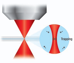
Figure 1.1 Schematic showing the net gradient force on a particle (larger than the wavelength of light) in a focused laser beam.
Basic Theory of Optical Tweezers
Optical Tweezers, or traps as they are often called, are created by using a high numerical aperture objective to tightly focus a laser beam, thereby creating a spot where a particle with dimensions on the order of microns will experience a force due to transfer of momentum from the scattering of photons.
Arthur Ashkin in the early 1970s originally demonstrated that optical forces can manipulate micro-sized dielectric particles in water (A. Ashkin. Phys. Rev. Lett. 24, 156 - 159 [1970] and A. Ashkin et al. Opt. Lett. 1, No. 5, [1986]). This technique has become an important tool in a wide range of fields such as bioengineering, material science, and physics due to its ability to hold and manipulate particles and to measure forces in the femtonewton and piconewton ranges.
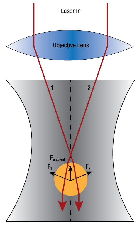
The relationship between particle size and the trapping wavelengths presents two regimes to consider when developing a theory to describe optical trapping. In the Mie size regime, the diameter of a trapped particle is much larger than the wavelength of light and trapping can be described using ray optics. Rays of light are refracted as they pass through the particle, exerting a force due to the momentum change. In the case where a particle is not aligned axially in the center of the laser beam, the rays closer to the center of the beam will be more intense and will transfer more momentum to the particle than those rays closer to the edge of the beam. This will apply a lateral "gradient" force to the particle towards the center of the beam. Once the particle is in the center of the beam, the rays refracting through the particle will be symmetric, and the particle will be laterally trapped.
The forces in the axial direction are more complex. As rays are backscattered at the solvent-particle interface, the light will transfer momentum to the particle, leading to a scattering force in the forward direction of the beam. With a particle near the focus of a laser beam, the gradient force Fgradient will act towards the focus, as shown in Figure 1.1. The resulting overall potential has the minimum slightly offset downstream from the focus of the beam. In order to trap particles in the image plane of the microscope, the laser focus has to be slightly offset to compensate for the scattering force.
In the Rayleigh regime, the diameter of the particle is much smaller than the wavelength and the ray theory breaks down. To understand the forces, the trapped particle is considered to be a point dipole. The scattering force arises from absorption and re-radiation, while the gradient force results from the interaction between the inhomogeneous field and the induced dipole (C. N. Keir and M. B. Steven. Review of Scientific Instruments 75, No. 9, 2004).
For particle sizes comparable to the wavelength, neither the Mie theory nor the Rayleigh theory applies; therefore, the electromagnetic field analysis is more complex. There are several references detailing this theory, such as E. Almaas and I. Brevik. J. Opt. Soc. Am. B 12, 2429, 1995; J. P. Barton, J. Appl. Phys. 64, 1632 (1988); P. Zemanek et al. J. Opt. Soc. Am. A 19, 1025 (2002); K. F. Ren et al. Opt. Commun. 108, 343 (1994).
Measuring Forces with Optical Tweezers
The capability of optical tweezers to measure forces on particles offers a unique and valuable tool for studying cell components such as biological proteins and molecular motors. Optical tweezers apply a force toward the focus of the trapping laser beam with a magnitude proportional to the distance of the particle from the focus for small displacements from the center of the trap. As the laser beam passes through a trapped particle, it will be deflected by an amount that depends on the position of the particle relative to the center of the trap. The deflection is converted to an electrical signal by a quadrant photodiode, which produces a voltage proportional to the particle position through back focal plane interferometry (F. Gittes and C. F. Schmidt. Opt. Lett. 23, No. 1, 1998).
Accurate force measurements depend on precise calibration of the force constant and the responsivity of the particle position detector, which varies with laser power and particle properties. Common methods for ascertaining the force constant are Power Spectral Density (PSD) roll-off, equipartition, and Stokes' drag.
In the PSD roll-off method, the power spectral density of a time series of trapped particle positions (due to Brownian motion) is computed. This is fit to the response of a harmonic oscillator with known damping due to the viscosity of the solvent. This is described by the equation:
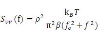
Here, Svv is the uncalibrated power spectrum, ρ is the linear voltage displacement calibration factor, kB is Boltzmann's constant, T is the temperature of the medium, β is the drag coefficient, and f0 is the characteristic corner frequency.
The equipartition method equates the average potential energy of the particle in the trap to the thermal energy of the solvent molecules. In the Stokes method, the sample is translated with a range of velocities. A force balance between viscous drag on the particle and the trap force is computed. Since each method relies on a different physical principle, the combined results provide a convenient way to verify the calibration. The PSD roll-off method offers a particularly effective way to discover an inaccurate position detector calibration, since it does not depend on the detector responsivity like the other two methods.
| Posted Comments: | |
| No Comments Posted |